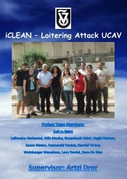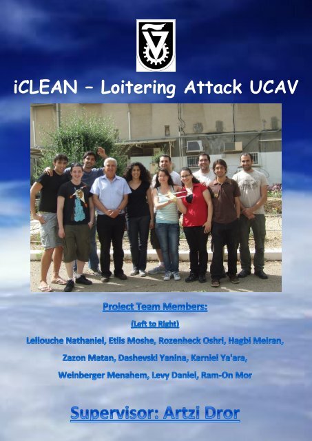
iCLEAN â Loitering Attack UCAV - aero.com
iCLEAN â Loitering Attack UCAV - aero.com
iCLEAN â Loitering Attack UCAV - aero.com

You also want an ePaper? Increase the reach of your titles
YUMPU automatically turns print PDFs into web optimized ePapers that Google loves.
<strong>iCLEAN</strong> – <strong>Loitering</strong> <strong>Attack</strong> <strong>UCAV</strong>1
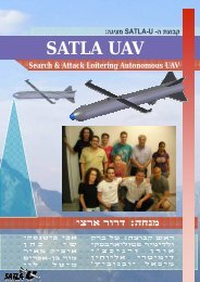
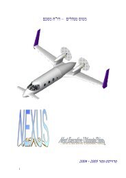
ABSTRACTThe following report summarizes the work process that had been doneduring the year of 2011-2012, as part of a student project of theAerospace faculty at the Technion Institute of Technology.The "<strong>iCLEAN</strong>" project."<strong>iCLEAN</strong>" is a suicide Unmanned Combat Air Vehicle (<strong>UCAV</strong>) withloitering and reconnaissance capabilities, designed to perform missionsbeyond line-of-sight in a range of 400 [NM] and for a long period of time,suggesting a long endurance of just about 5[hr].Carrying a 20+ warhead and equipped with an EO/IR (Electro-Optical andInfra-Red) sensor, the "<strong>iCLEAN</strong>" provides an advantage to the forces onthe ground and constitute a big threat on the enemy during <strong>com</strong>bat.During the work process a <strong>UCAV</strong> configuration survey was conducted,two configurations were chosen for the preliminary design.One of those configurations had been chosen due to several<strong>com</strong>parisons and requirements arose during the process.An improved detailed design and a wind tunnel model test wereconducted on the chosen configuration in order to ensure that thetheoretical calculations and design are valid.2
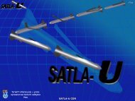
MARKET SURVEYMARKET SURVEY – CONFIGURATIONSA UAV's configurations <strong>com</strong>parison has been made.Eventually, Two Israeli attack UAVs configurations, manufactured by IAI,HARPY and HAROP, which has purpose and characteristics similar to thecustomer specifications, were chosen to be assessed in order to try andimprove the performances of this two.General CharacteristicsHARPY1) Delta wings2) Has an antenna that search a radar3) If target radar shouting off, when Harpy dives, it cancels theattack and continues patrolling.4) Weight: 135 kg (32kg Warhead)5) Performances: Max speed of 185 km/hr, and range of 500km,3-4hr endurance.6) Propulsion: UEL 37hp AR-731, Wankel engine.IAI HARPYIAI HARPY5
HAROPGeneral Characteristics1) Delta wings + Rear wings extension2) Canard front-plane3) Length: 2.5m, Wingspan: 3.0m4) Weight: 135kg (23kg Warhead)5) Performances: Max speed of 190 km/hr, and range of 1000km,6hr endurance.6) Propulsion: UEL 37hp AR-731, Wankel engine.IAI HAROPIAI HAROPHARPY, HAROP AND REQUIRED UAV COMPARISONRange Control Target type Weight Engine Warhead EnduranceHARPY500km Automated Static +active135kg AR731 32kg 4hrHAROP1000kmAutomated+remoteoperatorStatic,mobile +active135kg AR731 23kg 6hrRequired ~740km Automated+“man in theloop”Static,mobile+ active +passive100kg ? 20kg 5hrIAI UAVS AND REQUIRED UAV COMPARISON6
PRELIMINARY DESIGNWORK PROCESSDivided into two teams, evaluation started in order to end up with a finalpreliminary design of our system:8
tudi pristojnosti posameznih lastnikov navideznih omrežij pri upravljanju fizičnegaomrežja z namenom zagotavljanja nemotenega delovanja navideznih omrežij vnormalnih razmerah in še zlasti v izrednih razmerah.Vse komunikacije v navideznih omrežjih morajo biti zaščitene tako, da brez odobritveuporabnika navideznega omrežja niso dostopne iz drugih omrežij. Upravljavcemfizičnega omrežja mora biti onemogočen dostop do komunikacij v navideznihomrežjih.Za vse uporabniške skupine se v skladu z zakonodajo in predpisi za posameznapodročja delovanja državnih organov zagotovi uporaba neodvisnega in samostojnegaupravljanja navidezne omrežja.Varnost je lastnost telekomunikacijskega sistema, da zagotavlja varen in po potrebizaupen prenos podatkov. Za zagotavljanje varnosti mora DRO imeti:−−−−zaščito z večstopenjsko overovitvijo dostopa,kriptografsko zaščito radijskega vmesnika,kriptografsko zaščito podatkov na celotni poti med dvema ali več uporabniki terdaljinsko blokado in deblokado terminalov.2.6. Zahteve, povezane z upravljanjem in vzdrževanjemGlede na to, kdo je lastnik omrežja in kdo operater, so trije različni modeli:• model GO-GO (Government Owned – Government Operated): vlada je lastnikomrežja in operater,• model GO-CO (Government Owned – Company Operated): vlada je lastnikomrežja, podjetje je operater,• model CO-CO (Company Owned – Company Operated): podjetje je lastnik inoperater omrežja.Izbor uporabljenega modela pri graditvi sodobne radijske infrastrukture je odvisen odveč faktorjev, predvsem pa so pomembni naslednji:• razpoložljiva finančna sredstva,• zahtevana hitrost gradnje celotnega sistema,• stopnja razvitosti tehničnih služb javne varnosti oziroma morebitnihizvajalcev.Zaradi tehnično-tehnoloških lastnosti omrežja, predvsem pa zmogljivosti celotnegaomrežja, kakor tudi zaradi višine investicije je smiselno oziroma racionalno zgraditi leeno omrežje, prvenstveno namenjeno državnim organom, ki delujejo na področjujavne in nacionalne varnosti. Smiselno pa je razmišljati o možnosti, da to radijskoomrežje uporabljajo tudi drugi uporabniki, ki so pomembni z vidika nacionalnevarnosti ali pa delujejo na področju varnosti.Model GO-GOV Sloveniji trenutno poteka graditev enotnega DRO po modelu GO-GO v skladu ssklepom Vlade (136. seja, 05. 04. 2002) in Schengenskim izvedbenim načrtom (Vladadopolnila 23. 06. 2005). Glavni razlog je način financiranja, saj se zanj uporabljajorazlična sredstva, tako sredstva Evropske Unije (najprej Phare, zatem SchengenFacility), kot tudi finančna sredstva proračuna RS. Do sedaj je vse postopke v zvezi ssistemom izvajal državni organ (MNZ – Policija) in to zajema:• nabavo infrastrukturne opreme,Stran 11 od 36
After beginning with the first solution, a <strong>com</strong>parison between thestability of the configuration has been made. To have a suitable<strong>com</strong>parison, the stability margin of both of the UAVs when the wing andcanard are fully opened had to be between 10%-12% of the wing's rootchord.The <strong>com</strong>parison is shown in the following table:From the table above one can see that the 25%-75% configuration ismore unstable for small opening angles of wing and canard. Therefore,from now on, the configuration will be 40%-60% lift areas ratio betweenthe canard and wing.For bigger opening angles than 82.5, the UAV is stable. For smalleropening angles, it is still needed to find a solution for the lack of stabilitywhile opening the wings and the canard – placing the booster in anangle.12
Stability marginStability marginThe changes of the center of gravity and <strong>aero</strong>dynamic center as afunction of the opening angle:25%-75% configuration:20Stability Margin as a function of the Wing Opening Angle0-20X: 86.49Y: -0.05463-40-60-80-100-120-140-160Stability Margin [%]Stability Margin [cm]-1800 10 20 30 40 50 60 70 80 90opening angle [deg]40%-60% configuration:20Stability Margin as a function of the Wing Opening Angle100-10X: 82.53Y: -0.05275-20-30-40-50-60Stability Margin [%]Stability Margin [cm]-700 10 20 30 40 50 60 70 80 90opening angle [deg]13
MOMENT VS. TIME FOR DIFFERENT BOOSTER ANGLESI order to <strong>com</strong>plete the pitch-up solution, placing the booster in an anglewas tasted. This angle should cause negative moment and by this willcancel the pitch.At the sketch r,R –are distances that changing in time.To examine this solution, graphs of the moment vs. time (while theunfolding of the wings) where plotted for different angles. There is aneed to confront with the change of mass and pressure centers due towings opening.The above graph shows how the moment changes with time at differentangles from to .The conclusion is: when the angle equals the moment's sum is zero,so by placing the booster at this angle there will be no pitch.14
7.5. AERODYNAMICMany and varied <strong>aero</strong>dynamic calculations have been made for the newand improved configuration:Lift Calculation Results:PropertyResultLift coefficient slopeLift coefficient as a function ofangle of attackMinimal lift coefficient at height of0ft and 5000ftIncidence anglesMaximal lift coefficientC L , CLCC 1 6.086rad 0.721 6.086 Lminheight0ftLminheight5000ft 0.317 0.395iw0.131[ rad] 9 ic 0.079[ rad] 4.5C 2.11LmaxStall angle 0.228[ rad] 13.1stallZero lift angleC 0 0.118[ rad] 6.8LDrag Calculation Results:PropertyResultDrag coefficient as a function of liftcoefficientCD0.02 0.056C2L15
PERFORMANCE CALCULATIONSMany and varied performance calculations have been made for the newand improved configuration:Thrust Calculation Results:PropertyResultMaximum thrustTmax 28[ lbf ] 902.7[poundal ]Minimum thrustTmin 14.7[ lbf ] 473.6[ poundal ]Thrust for cruise flightT 15[ lbf ] 489.5[ poundal ] 53.5% T maxVelocity Calculation Results:PropertyResultMinimum velocity (stall) - height of 0ftand 5000ft.Maximal velocity ft Vstall70.6 41.8[ knot]height0sec ft Vstall78.9 46.7[ knot]hight5000ft secVmax 110[ knots]16
Climb & Turn Calculation Results:PropertyResultMaximum climb angleMaximum dive angle climbmaxdivemax0.49[ rad] 28.2 0.51[ rad] 29.2Minimum turn radius withoutclimbing (n=4)Rmaxturn 50[ ft]Turn radius at n=2.5Rn2.5 84.6[ ft]Range and Endurance Calculation Results:PropertyResultMaximum range for climbMaximum endurance for climbMinimum range for cruiseMaximum endurance for cruiseRclimb 10.6[ NM ]Eclimb10 minRcruise 371[ NM ]Ecruise 4.6hr17
WING DETAILED DESIGNWING ROOT JOINTSThe wing root joint is one of the most critical areas in aircraft structure(especially for fatigue). It basically has two types of wing joint design:Fixed joint, Rotary joint.The second type will be used in this design.Several principles should be preserved to make the joint most efficient:- It is important to keep the joint short (a long joint tends to pullload in from adjoining areas).- Holes sizes should be held as tight as practical.- Correlation of small <strong>com</strong>ponent test results with analyticaltechniques will increase the probability of successful selection.Several pivot mechanisms was examined.Most studies made for alternates designs suggest → Vertical pin designMechanismVertical pinAdvantages- Structural simplicity- Load paths determinedwith Confidence- Minimum volume of hinge- Simple actuator mechanism- Very few moving parts- Minimum weightDisadvantages- High journal bearing stresses- Great local wing thickness- Great reliance upon theintegrity of single-load paths- Can be modified to provide additional fail-safe features- Has been applied on modern variable sweep wings- Provides the lightest structural arrangement- Provides the least interruption to the wing bending- Used in many platforms18
Wing dynamics:- Bending moment taken across as a couple of equal andopposite loads acting parallel to and in the plane of theupper and lower skins- A vertical pin through the pivot axis transfer the coupleto the movable outer wing to the fixed center sectionTwo basic designs of the Vertical-Pin joint:19
Modeling of the wing-pivot connection:21
PIVOT STRESS CALCULATIONS AND ANALYSISSTRESS CALCULATIONSAccording to evaluate the stresses applied on the pivot:Forces and moments distribution on trapeze wing: Triangular wing distribution(Resultant force on one third of the wing) Force causes a bending moment on the wing's root. Root moment as referred as a couple of forces on the pivot.As we can achieve from stresses analysis calculations -The applied stresses are lower than the allowed stresses:122.3[ MPa] 706.3fibersallowedCarbon fibersMPa MPa16 allowed270.8Al . 7075T6hingeMPa22
ANALYSIS SIMULATIONA stress analysis was generated by the "ANSYS" software to validate thewing design.The analysis used an aluminum wing instead of carbon wing due to thesoftware limitations.Shear stresses:Maximal stresses - Von Mises:23
Deflection:To evaluate the results for the carbon wing, a stress factor wascalculated as followed:allowed carbon fiberallowed aluminum706.3270.82.6Thus, the maximal deflection of the wing:MaterialAluminumCarbonMax. Deflection[mm]62.324
WING'S FOLDING MECHANISMThe opening-wing and canard system:DESCRIPTION OF THE DISPLAYED SOLUTION1. The purpose is to design an opening set like the "Long Shot" by"Lockheed Martin" with a <strong>com</strong>bination of the popular"diamond back".2. The mechanism of the wing's opening is a stretched spring that hasbeen placed between the two wings. This slit is leaded by aconducted one.3. The process of opening the wing is fully automated duringlaunch time.The tracks move along with the wings until the UAV leaves thecanister. At that moment, the tracks fall and the wing openingsystem starts working automatically.4. During launch preparations, the wings are kept closed.25
DragDirection offlightThe weight of the wing was not considered in the calculations, butthe lift that its producing was considered. By this consideration wehave increased the safety factor of both the hinge and the bearingtogether.The length of the connecting rods and the angles were determined ina way that the wings will be on the same line in the openedconfiguration.In order to choose the spring and to perform the calculations, weused the sizes of the rods and their angle's position.CHOOSING OF THE MAIN SPRING:MECHANISM COMPONENTSThe spring's mechanism is made up of: a spring, a rod which on topof it the spring is placed and a pin which leads the spring on top ofthe rod and attached to the connecting rods. The whole mechanism isplaced in track on a coordinating surface.The spring is stretched while the wings are folded. While launchingthe UAV, the spring is released and opens the wings.26
TensionDragTension forces that applied on the spring during opening of thewing/canard .The spring have to over<strong>com</strong>e those forces and to open thewings.The chosen spring equals the moment to the one that creates the dragforce .The spring's specifications:MOVEMENT LIMITERS DESIGN:The Limiters of the wings are designed in order to lock the wings at theopened state. When the wings are open, the spring is released and thelimiters lock and stop the wings. The limiters are placed in thecoordinating surface. While the wing is closed it holds the limiterpressed inside. While the wing is opened there is a hole above thelimiter. The limiter enters this hole and locks the wing according to thecoordinating surface.27
The limiters are close to the rotating hinge so they are not sufferingshear forces. For that reason we will choose such diameter that will stopthe wing and lock it stable. The spring that lifts the limiter doesn't suffersignificant forces as well, so we need a spring which over<strong>com</strong>es thelimiter weight.LIMITER MODEL28
FINAL CONFIGURATIONAs demonstrated earlier, the last iteration of the UAV configuration isshown below:General Geometry Properties:PropertyWeightAirfoil (EPPLER 560)Aspect ratioW 220[ lbf ] 1 Cl max1.83; Cl 0.8; Cl, 4.10rad 14.5 0.37[ rad], 6.5 0.11[ rad]stallzero liftlineA 9, A 11, A 0.5wing canard fuselageReference lift area andSref217.6[ ft ]S ft C ft C ft2wing 10.5[ ], r, wing 1.2[ ], t,wing 0.9[ ]S ft C ft C ft2canard 7.1[ ],r, canard 0.9[ ],t,canard 0.7[ ]chords2FuselageS 8.7[ ft ], L 6.7[ ft]fuselagefuselageVertical tailSpansAerodynamic center’spositionS 1.4[ ft ], C 1.3[ ft], C 0.6[ ft]2v. tail r, tail t,tailb wing 9.8[ ft], b canard 8.9[ ft] , b tail1.5[ ft]xw4.9[ ft], xc2.0[ ft]z 0.4[ ft], z 0.1[ ft]wc29
As for the wings and canards slots we designed a concept to close themafter they open, because of <strong>aero</strong>dynamic considerations. The solution issome kind of a "curtain" as following:This is a draw of a section from the middle of ourplane. The plane itself is painted in black. Thesmashed line indicates the space to the wing/canard.In red is the "curtain" itself, made of plastic, with a2 mm thick and in blue is a aluminum 2024 strip thatconnect the curtain to the plane body.INTERNAL LAYOUT OF THE COMPONENTSIn this draw it can be the main <strong>com</strong>ponents of the plane; the avionicsand the EO/IR sensor in the front, the motor and the booster in the backand the integral warhead and fuel tank in middle.The <strong>com</strong>ponents positions decide in iterative way, according to theweight table described next (Wishing the fuel tank to be positioned inthe center of gravity area).30
WEIGHTS TABLEThe table below describes the center of mass as calculated by Excel:S/N Part name Mass[gr] X[cm] My[N*cm]1 Structure Fuselage 10111 110 129111 Wings 2471 170 90543 Mechanics –wing 3011 170 79457 Reinforcements- wing 1111 170 15700 Canard wings 7121 0050 11112 Mechanics-canard 1111 0050 11594 Reinforcements- canard 1111 0050 0775 Tail 1111 150 32319 Fuel injection system 3111 131 351211 Engine Engine 2511 190 1311511 Fuel 10111 114575 1031711 Fuel tank 1111 114575 111113 Oil 1111 111 114917 Warhead Warhead 11111 45 1100410 Payload Sensor 5111 3151 134112 Battery 0111 151 551914 Avionics Computer+Control system 1111 1450 373Total Mass : 95111CGx[cm]: 114575The table above is displaying the position of the center of gravity whenthe wings and the canard are closed. As it can be seen in the table, thecenter of gravity in closed position is distanced 107.5 cm from thereference point (the front of the UAV) in order to gain a stability marginof about 10%.31
WIND TUNNEL TESTIn order to proceed with the performance calculations and flight controldesign, and validating our design as it is, a wind tunnel test had to beconducted to determine the stability derivatives and <strong>aero</strong>dynamiccharacteristics of a real model of the UAV. First, a wind tunnel wasdesigned, and then manufactured using a rapid prototyping method. Thetest was conducted at a subsonic tunnel due to its <strong>com</strong>patibility with ourrequirements and flight conditions.A full testing plan was established and carried out, testing the aircraft<strong>aero</strong>dynamic behavior in the presence of various angle of attack, slipangles, with and without canards.The whole process will described next.MODEL SIZINGGeneral instructions:1. Max. Length: 100 cm – As a result of balance rod length, stabilityand sensitivity limitations.2. Max. Section area: 2-4% of cell’s section area.3. Model should be as light as possible – In order to minimize thenon-<strong>aero</strong>dynamic loads on the balance rod and keep results asaccurate as possible.4. Rear mount for balance rod should be bigger by about 6 mm thanthe balance rod’s diameter in order to prevent any contactbetween the internal surface of the model and the balance rod.5. Model shouldn’t be too small in order to get accurate results.6. Wing tips should be away from the cell’s walls - In order toprevent any flow disruptions near the cell walls.According to the <strong>UCAV</strong> real flight conditions we have done theexperiment in the sub-sonic wind tunnel, and due to the tunnelproportions the max width of our <strong>UCAV</strong> model could be 50 cm so wecreated a scale replica of 1:7 scale from the 3m wing span <strong>UCAV</strong> usingthe method of Rapid Prototyping (3D printing).32
THE FULL ASSEMBLY OF THE MODELAs it can be seen the wind tunnel model is about 30cm long and has awing span of 44cm.It was decided to make the adapter stationary, and its location will beat the mean location of the pressure centers that we’ll get, eventhough it will cause some errors.33
PRINTING THE MODEL – THE RESULT OF THE PROCESSAfter fulfilling the instruction about the maximum size of a part,which led us “breaking” the model into parts (nose, body and tails,wings, canards) here are the results:Nose is being held by pressure, wings and canards are being held bysteel spacers and hinges. Also, steel reinforcements were inserted tothe wings and canards34
The different configurations:OPENED, CLOSED AND OPEN WITH TUFTS TEST MODELOPEN WING ONLY WITH TUFTS, BODY ONLY TEST MODEL35
WIND TUNNEL TEST RESULTSThe results of the wind tunnel were <strong>com</strong>pared with the theoreticalcalculations. The results are displayed in the following graphs:The theoretical results for the whole aircraft are very accurate. The onlybig difference between the results is between the stall angles – the windtunnel stall angle is 18 degrees and the theoretical stall angle is 13.1degrees. This difference can occur because vortexes are created on thetips of the winds in the tunnel and create a smaller effective angle onthe wings.For the <strong>com</strong>parison between the wind tunnel and the theoretical resultsfor each lift <strong>com</strong>ponent, the results are not so close:1- For the fuselage, a wrong choice of the 2D slope lift line ( 2 rad)is probably the cause for the difference between the slopes of thegraphs.- For the wing's lift coefficient, the lack of consideration of thebody-wing effects on each other (can enlarge the lift) is probablythe cause for the offset between the graphs.36
The canard's lift coefficient isn't <strong>com</strong>pares because these results werenot tested in the wind tunnel and was estimated for the theoreticalcalculations.We expect to see a difference between the results because of the ducttapethat was on the model in the wind tunnel test, because thelongitudinal gauge is the most inaccurate gauge and the drag results arevery small (the error will be the biggest for the drag) and because of thebase drag of the model. The results are quite close (in the shape of thegraph and for some angles of attack). The biggest difference is betweenthe form drag coefficients – the theoretical guess is 0.02 and the windtunnel results shows 0.056. The form drag coefficient results cannot be<strong>com</strong>pared because of the duct-tape.37
0.2C Mas function of C Lfor Open Configuration0-0.2-0.4-0.6C M-0.8-1-1.2-1.4Whole Aircraft - Tested - 45 m/secWhole Aircraft - Tested - 30 m/secWhole Aircraft - Theoretical Calculations-1.6-1.5 -1 -0.5 0 0.5 1 1.5 2 2.5 3C LThere is a big difference between the results. An explanation for thisphenomenon can be the smaller speed than needed. A proof for thisexplanation is the enlargement of the divergence in smaller speeds (for30 m/sec). The model is trimming only on deep stall (very negative liftcoefficient). There is a need to consider this phenomenon on the controlsection.Additional Conclusions:1. Additional strengthening of the wind tunnel model is needed so itcan be able to carry the lift loads of 80 m/s air speed, and by thatto get the necessary Re number and get more accurate results.2. Additional experiments have to be performed on the wings andcanards in order to evaluate their mutual effect on each other.38
CONTROL SYSTEMSIMULINK MODELWe have modeled the entire control system, using standard atmospheric(ISA). We also modeled all of the control loops for the delta_T bodyu_dotaxis states[delta_e]delta_eand wind axis states.[u]u w_dotThe Simulink model for pitch- rate and speed controller:[delta_t][q][h][delta_t][theta][delta_e][u][w][q][h][theta]w_g[w]wqfcnq_dothdelta_Th_dotu_dotthetadelta_euw_gw_dot w_g theta_dotwq_dot MATLAB Functionqfcnhh_dotthetaw_gtheta_dot[w_dot][h_dot][w_dot][h_dot][u_dot][q_dot][theta_dot] Scope7Scope5theta_<strong>com</strong>Scope5[theta]K_thetatheta_<strong>com</strong>[q]Scope6 [theta]K_thetaK_qMATLAB Function-10s+10Transfer Fcnt_con-10s+10Transfer Fcnt_conScope7[delta_e][delta_e][u][q]Scope6U_<strong>com</strong>U_<strong>com</strong>[u][u][u_dot]K_qK_uK_uKu_dots+0.5scontrollers+0.5 0.25s s+0.25controllerv_con Engine0.25s+0.25Enginev_con[delta_t][w] [delta_t][theta][q]Scope9[h][u_dot]Ku_dot[w][w][w][w][u]Scope9Scope4 u[u_dot]Scope4[gamma]-T-[V][u][u]u[V][u]39
40alpha_<strong>aero</strong>gamau_dothqthetawuScope9Scope8Scope7Scope4Scope3Scope2Scope11s1s1s1s1s[w_dot][u_dot][gamma][alpha][alpha_<strong>aero</strong>][theta][h][q][V][delta_t][delta_e][theta_dot][h_dot][q_dot][w][u][alpha][theta][w][w][theta_dot][h_dot]-T-[gamma][u_dot][q][h][theta][u][w][q_dot][V][V][w_dot][u_dot]w_g
[deg]RESULTSBy entering the coefficient values as an assumption or by derived fromthe wind tunnel test, the simulation was running for a local level runs.We analyzed the control design by checking the step-response, onlooking the bode graphs to get the PM and GM:1.2Project 086755 – 029977584 – Mor Ram-On10.80.60.40.20-0.20 10 20 30 40 50 60 70 80 90 100Time[sec]STEP INPUT FOR As can be seen, in the sp, there is no steady state error for <strong>com</strong>mand.41
u dotq[deg/sec][ft/sec 2 ]1Project 086755 – 029977584 – Mor Ram-On0.80.60.40.20-0.2-0.40 10 20 30 40 50 60 70 80 90 100Time[sec]0.2STEP INPUT FOR uProject 086755 – 029977584 – Mor Ram-On0.10-0.1-0.2-0.3-0.4-0.50 10 20 30 40 50 60 70 80 90 100Time[sec]PITCH-RATE RESPONSE42
u[ft/sec]0.02Project 086755 – 029977584 – Mor Ram-On0-0.02-0.04-0.06-0.08-0.1-0.12-0.14-0.160 10 20 30 40 50 60 70 80 90 100Time[sec]u RESPONSE43
SUMMARYThis report unites all the hard work done during the last semesters as part of astudent's final project.In order to satisfy the demand for a loitering suicide <strong>UCAV</strong>, we had to gather andto implement all the knowledge and abilities obtained through our studies at thefaculty of Aerospace Engineering at the Technion Institute of technology, and evenmore. Moreover, during the process we had been exposed to the <strong>com</strong>plexity of theUAV's systems, sub-systems and the demanding nature of work in the industry.We experienced work in small and large groups, focusing on several areas andsystems, both required vast market and literature surveys.Under our supervisor supervision we manage to integrate all the pieces togetherinto a whole new system, UAV.During the project, the following were ac<strong>com</strong>plished:Market survey and preliminary design.Configuration selection and detailed design of the following: Wings opening mechanism Wings structure design Internal layout and weight distribution Propeller selection Airfoil selection Body structure designDetailed analysis: Aerodynamics of the UAV Wings and body; load and stressA wind tunnel model test and a detailed design were conducted onthe chosen configuration to insure that the theoretical calculationsand design are valid.Initial Guidance, Navigation and Control (GNC) systemwas established.Eventually, we were able to design a new <strong>Loitering</strong> Suicide <strong>UCAV</strong> which met mostof the original costumer requirements; almost satisfy the demanding range andendurance requirements, maximize the number of units on an ordinary launchervehicle, able to withstand different conditions and situations.There is still a need to verify the launch problem solutions and optimize the wingsand canards according to their effects on one another.According all the above, this project manage to fulfill its most important andfundamental goal – to make us a lot better engineers before we get out fromgraduation to the real world!44