wind tunnel paper.pdf - aero.com
wind tunnel paper.pdf - aero.com
wind tunnel paper.pdf - aero.com

You also want an ePaper? Increase the reach of your titles
YUMPU automatically turns print PDFs into web optimized ePapers that Google loves.
LESSONS FROM WIND TUNNEL MODELS<br />
MADE BY RAPID PROTOTYPING<br />
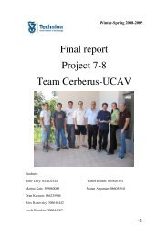
Dror Artzi<br />
Faculty of Aerospace Engineering<br />
Technion – Israel Institute of Technology<br />
Technion City, Haifa 32000, Israel<br />
Ehud Kroll<br />
Faculty of Aerospace Engineering<br />
Technion – Israel Institute of Technology<br />
Technion City, Haifa 32000, Israel<br />
ABSTRACT<br />
Wind <strong>tunnel</strong> model design and construction has traditionally been a relatively long, tedious<br />
and expensive process. Rapid Prototyping (RP) technologies, which have been used for<br />
general geometrical modeling, have recently been applied to <strong>wind</strong> <strong>tunnel</strong> model production.<br />
In spite of our initial doubts as to the adequacy of the RP techniques for this purpose, we<br />
have produced two models of airplanes designed by students as part of their final-year<br />
project. Both models consisted of four main parts: fuselage, nose section and two wings, plus<br />
an assortment of small, interchangeable control surfaces. They had a wing span of 600 mm<br />
and their structure was reinforced with metal inserts to provide added stiffness. The results of<br />
testing the models in a subsonic <strong>wind</strong> <strong>tunnel</strong> indicate that <strong>aero</strong>dynamic data of acceptable<br />
quality can be collected from rapid prototyping models while offering significant cost and<br />
production time advantages over machined metal ones.<br />
INTRODUCTION<br />
The technology of Rapid Prototyping (RP), which has been around for over 20 years, allows<br />
the fabrication of a physical object directly from the CAD model in an additive, layer-bylayer<br />
manner. The prototypes are made of various materials, such as polymers, metals and<br />
<strong>paper</strong>, using different technologies. A promising application of RP is the production of <strong>wind</strong><br />
<strong>tunnel</strong> models for checking, verifying and generating data such as lift and drag coefficients,<br />
pressure distributions, etc. Traditional <strong>wind</strong> <strong>tunnel</strong> models are made of aluminum or steel by<br />
5-axis CNC milling, take weeks or months to fabricate, and cost tens, even hundreds of<br />
thousands of dollars [1]. A number of case studies show that making <strong>wind</strong> <strong>tunnel</strong> models by<br />
RP can produce good results in terms of <strong>aero</strong>dynamic performance and characteristics, while<br />
incurring a five- to tenfold reduction in cost and a significant shortening of acquisition time.<br />
Landrum et al. [2] tested three 30-cm span by 10-cm chord airfoil models in a low-speed<br />
subsonic <strong>wind</strong> <strong>tunnel</strong>: a conventional cast polyurethane model and two photopolymer models<br />
made by stereolithography (SLA). All three models were identical except for the light<br />
sanding of one of them to produce a smoother surface finish. They reported <strong>com</strong>parable<br />
fabrication times and dimensional tolerances for the RP and conventional models, with the<br />
biggest difference being in the drag coefficient for both the RP models, which was about half<br />
the value measured for the cast model. They attributed this result to the rougher surface of the<br />
RP models inhibiting the formation of laminar separation bubbles.<br />
Springer and Cooper [3] <strong>com</strong>pared the static stability <strong>aero</strong>dynamic characteristics obtained in<br />
a trisonic <strong>wind</strong> <strong>tunnel</strong>, over a range of Mach numbers from 0.3 to 5.0, for models made by<br />
three different RP technologies, and one control model made of aluminum. They tested<br />
models made of ABS plastic by fused deposition modeling (FDM), photopolymer resin made<br />
2
y SLA, and glass reinforced nylon made by selective laser sintering (SLS). All the models<br />
were of a wing-body-tail configuration launch vehicle with area S ref = 8.68 in 2 and length L ref<br />
= 8.922 in. They concluded that at the present time (1997), only preliminary design studies<br />
and limited configurations could be used due to the RP material properties that allowed<br />
bending of model <strong>com</strong>ponents under high loading conditions. However, for obtaining<br />
preliminary <strong>aero</strong>dynamic databases, the RP models offered significant cost savings and<br />
fabrication time reductions at acceptable fidelity.<br />
Hildebrand et al. [4] and Tyler et al. [5] described two <strong>wind</strong> <strong>tunnel</strong> models, a 4-ft span by 3-ft<br />
long X-45A UCAV, and a 20-in. span lambda wing-body configuration Strike Tanker, made<br />
by SLA (plastic) and SLS (stainless steel) techniques. They investigated issues such as the<br />
integration of pressure taps (small holes on the surface and internal airtight passageways to<br />
the transducers), model sagging under load, dimensional accuracy and cost and time of<br />
fabrication. They found that it was necessary to stiffen the Strike Tanker plastic model to<br />
prevent excessive wing deflection, and did it by building the model parts around a 1/4-in.<br />
thick support plate. This construction principle was also described by Heisler and Ratliff [6],<br />
where a steel tube constituted the strong back of missile models, and plastic RP parts (made<br />
by FDM) were attached to it to establish the outer shape.<br />
A 2-m long model (1:8 scale) of the European Tiltrotor aircraft was built and tested at speeds<br />
up to 50 m/s [7]. RP technology was used to fabricate the external fairings of the model out<br />
of a <strong>com</strong>posite aluminum- and glass-filled polyamide-based material (Windform ® GF). These<br />
<strong>com</strong>ponents were mounted onto a machined metallic central frame. Satisfactory results were<br />
reported with only two drawbacks identified: wider dimensional tolerances and worse surface<br />
finish of the RP parts <strong>com</strong>pared to conventional <strong>com</strong>posite lamination models.<br />
Nadooshan et al. [8] tested a wing-body-tail configuration of a polycarbonate model made by<br />
FDM against a conventional machined steel model over a range of Mach 0.3 to 0.7 and angle<br />
of attack range of –2 to +12 degrees. The model’s length was L ref = 200 mm and area S ref =<br />
48 cm 2 . The results were a generally good agreement between the metal and plastic models<br />
up to about 10 degrees of angle of attack, when the plastic model’s deflection under the<br />
higher loading produced more noticeable differences.<br />
The current <strong>paper</strong> presents the design of two <strong>wind</strong> <strong>tunnel</strong> models made by RP as part of finalyear<br />
students’ projects [9, 10] and some of the lessons learned. Both models shared the<br />
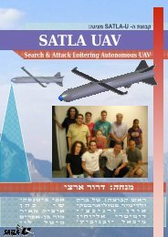
flying-wing configuration (see Fig. 1), but belonged to very different UAV designs. ILAS<br />
was a low-altitude, quiet, fuel-cell powered observation aircraft carrying a 2.5-kg electrooptical<br />
payload. It had a wing span of 3 m and was designed to fly at 20-25 m/s. CERBERUS<br />
was a low-RCS, long-range (1500 NM) UAV, carrying two 500-kg bombs and a variety of<br />
sensors. Its wing span was 13.2 m and cruise speed M=0.8.<br />
Contrary to machining of metal models, RP technologies offer some unique characteristics,<br />
capabilities and limitations that will be discussed first. Next, the <strong>aero</strong>dynamic and structural<br />
design and manufacturing aspects of the models will be explained. The <strong>wind</strong> <strong>tunnel</strong> test<br />
results will then be presented, followed by our conclusions and re<strong>com</strong>mendations for future<br />
work.<br />
3
(a)<br />
Figure 1: Preliminary CAD models of the (a) ILAS [9] and (b) CERBERUS [10] UAVs.<br />
(b)<br />
RAPID PROTOTYPING<br />
One of the lowest cost RP technologies, known as 3D printing, was used for this work. The<br />
model is built in layers from the bottom up, by accurately depositing liquid photosensitive<br />
polymer droplets and curing them by ultra-violet light. Another, gel-like material is used as<br />
temporary support for overhanging features, and is washed away by high-pressure water jet<br />
when the fabrication process is finished. Machines used in this study where Eden 250 and<br />
Connex 500, both made by Objet Geometries, Israel. Model materials were FullCure 720 and<br />
VeroBlue. Model fabrication was carried out at the Technion, Israel.<br />
The following are the advantages offered by the RP technology to <strong>wind</strong> <strong>tunnel</strong> model<br />
building:<br />
Cost: RP model cost is directly related to the weight of materials (model and support)<br />
used in the fabrication. This means that producing hollow parts, and ―digging out‖<br />
pockets in the model, for example, lowers the cost, as opposed to the additional<br />
<strong>com</strong>plexity and cost involved in such operations when done by machining. We estimate<br />
that model production using RP for the two cases described in this <strong>paper</strong> was at least 5 to<br />
10 times cheaper than making metal models. A byproduct of the low cost is that aircraft<br />
designers can make many more models, testing multiple variants, when using RP.<br />
Time: Making a <strong>com</strong>plicated and relatively large model can take on the order of one or<br />
two days because the layers are very thin (16 m). However, the actual production<br />
process can be unsupervised, and it is very <strong>com</strong>mon to have the RP machine work 24<br />
hours a day. Even when RP models are not fabricated in-house, the <strong>com</strong>mon standard<br />
nowadays is that the <strong>com</strong>puter files are sent through e-mail to a service bureau, the<br />
model is made within a day or two, and sent back by courier. This is certainly much<br />
faster than producing a metal model by machining.<br />
Geometrical <strong>com</strong>plexity: The <strong>com</strong>plexity of the geometry that can be created by RP<br />
technologies is almost endless. For <strong>wind</strong> <strong>tunnel</strong> models, this allows hollowing out the<br />
models to reduce their weight, and making internal passages for pressure measurement or<br />
for smoke discharge for visualization. The <strong>com</strong>mon double curvature geometry of<br />
external aircraft surfaces, which makes machining them <strong>com</strong>plicated and expensive, does<br />
not present any added difficulty for RP.<br />
4
Weight: The RP model material is a polymer whose relative density is about 1.1. This<br />
means that the model would be significantly lighter than similar steel or even aluminum<br />
models, allowing the use of a more sensitive force balance in the tests. A byproduct of<br />
making a hollow model is that its cost is lower, because less material is consumed in its<br />
fabrication.<br />
Accuracy: Horizontal (x-y directions) resolution of the machines used is better than 0.1<br />
mm, and layer thickness (z-direction resolution) is 16 m, so the models are very<br />
satisfactory in this sense. However, all RP techniques approximate the original CAD<br />
geometry as small facets (i.e., planar surfaces instead of real curved ones) through the<br />
conversion of the model data to STL format, and this introduces some inaccuracy.<br />
Surface finish: The thin layers assure a smooth finish. Although ―step marks‖ can be<br />
seen and felt, they do not seem to represent a roughness that is greater than with fine<br />
machining. If smoother surfaces are desirable, than sanding can easily be applied to the<br />
polymer.<br />
Small parts and details: Some RP techniques, including the current PolyJet TM and<br />
PolyJet Matrix TM ones, allow producing small parts and fine detail. The manufacturer’s<br />
re<strong>com</strong>mended minimum thickness is 0.6 mm, but we managed to produce even finer<br />
detail. Figure 2 shows a set of relatively small spoilers that were made for the <strong>wind</strong><br />
<strong>tunnel</strong> testing.<br />
Figure 2: Small, detailed spoilers fabricated for the <strong>wind</strong> <strong>tunnel</strong> testing.<br />
Moveable parts: Although not utilized in the present work, <strong>com</strong>plete assemblies with<br />
<strong>com</strong>ponents that have relative motion may be produced directly by RP by specifying a<br />
proper clearance between the parts. This clearance is filled with support material during<br />
the fabrication, and when the support is washed away, the parts are free to move relative<br />
to each other.<br />
Disadvantages of RP for <strong>wind</strong> <strong>tunnel</strong> models are:<br />
5
Strength and Stiffness: Both are significantly lower than for steel or aluminum. The<br />
manufacturer of our RP machines quotes 55-60 MPa of tensile strength, 79-84 MPa of<br />
<strong>com</strong>pressive strength, and modulus of elasticity of 2.7-2.8 GPa [11]. These numbers are<br />
also confirmed by other experiments [12, 13] and are, of course, considerably lower than<br />
those for metals. Additionally, the strengths listed here are in the plane of the layer, while<br />
those in the build direction (vertical, z-axis, or perpendicular to the layer), dominated by<br />
the intra-layer adhesion strength, are about one-half of the quoted numbers. This<br />
anisotropy must be taken into account when designing the model and when determining<br />
the orientation of the built parts in the RP machine.<br />
Durability: The manufacturer reports [11] an Izod impact strength of 24 J/m. This means<br />
that small features may be quite vulnerable to accidental impact by other objects and<br />
consequently, to fracture.<br />
Stability: The photopolymers used in our models lose their strength when temperatures<br />
rise. Kim and Oh [12] report that the room temperature strength drops by 25% at 30°C,<br />
and by 50% at 40°C. We have also observed distortion of RP models (not the <strong>wind</strong><br />
<strong>tunnel</strong> models of this <strong>paper</strong>) over time. Models stored at room temperature sagged<br />
significantly under their own weight over a period of several months from the date of<br />
manufacture.<br />
Maximum Size: Each RP machine has a maximum build size. We used two machines,<br />
with 250x250x200 mm and 340x340x200 mm maximum part dimensions, respectively.<br />
Larger parts are usually made of several <strong>com</strong>ponents, which are later mechanically<br />
connected or glued together.<br />
MODEL DESIGN AERODYNAMIC CONSIDERATIONS<br />
The design of a <strong>wind</strong> <strong>tunnel</strong> model is a <strong>com</strong>bination and tradeoff of several requirements<br />
such as cross section area of the available and economical <strong>wind</strong> <strong>tunnel</strong>, actual size and shape<br />
of the aircraft to be evaluated, actual performance (speed, Mach number) of the air vehicle,<br />
similarity parameters, Reynolds number, materials and production process of the model and<br />
more. Since the actual CERBERUS UAV design speed was 0.7-0.8 Mach number, the first<br />
iteration of the model design was based on the size of the transonic <strong>wind</strong> <strong>tunnel</strong> where the<br />
<strong>com</strong>pressible flow effects could be included. This attempt, shown in Fig. 3, resulted in too<br />
small a model, scaled at 1:40 with a wing span of 350 mm.<br />
Another problem with this design was that the sting-type strain gage balance produced an<br />
excessively large ―cut‖ in the aft part of the fuselage, thus altering the <strong>aero</strong>dynamic shape to<br />
be tested. Therefore, an alternative <strong>wind</strong> <strong>tunnel</strong>, the subsonic one, with a larger cross section<br />
was selected, and similarity parameters applied. This resulted in a model scaled at 1:22 with a<br />
wing span of 600 mm, as shown in Fig. 4.<br />
The <strong>aero</strong>dynamic coefficients should be corrected for <strong>com</strong>pressible flow. Although the<br />
Prantl-Glauert transformation is not valid for transonic range in general, by considering the<br />
swept wing and the Mach number perpendicular to the wing, the following transformation<br />
can be used:<br />
6
Figure 3: First CERBERUS model design iteration with scale of 1:40.<br />
Figure 4: Second CERBERUS model design iteration with scale of 1:22.<br />
where M n is the Mach number perpendicular to the wing , M is the Mach number, is the<br />
wing sweep angle, C <strong>com</strong>p is the <strong>com</strong>pressible pressure coefficient, C in<strong>com</strong>p is the<br />
in<strong>com</strong>pressible pressure coefficient, and is the <strong>com</strong>pressibility (relative volume change).<br />
7
MODEL DESIGN STRUCTURAL CONSIDERATIONS<br />
The <strong>wind</strong> <strong>tunnel</strong> for our experiments is fitted with a rear-mounted sting-type strain-gage<br />
balance, with its forward section tapered (Morse cone) to accept a mounting adaptor for<br />
models. Because the model plus cone adaptor are attached to the front of the balance, the<br />
design needs to provide this access. Another consideration in determining the overall model<br />
architecture is the limitation on maximum part size, which did not allow fabrication of the<br />
whole span as one piece. All this led to a configuration that consisted of four main parts:<br />
fuselage, nose section, left wing and right wing for both models. These <strong>com</strong>ponents are<br />
shown in Fig. 5 for the ILAS model.<br />
Figure 5: Model architecture for the ILAS model showing the four main parts: fuselage, nose<br />
section and two wings.<br />
As is <strong>com</strong>mon with <strong>wind</strong> <strong>tunnel</strong> testing, ailerons, elevons and spoilers in the models were<br />
manufactured as separate parts, each representing a different position of the control surface.<br />
For easy changing of these parts, the models incorporate slots and other locating features, and<br />
means of securing the interchangeable parts: pins or screws. Figure 6 is a photograph of the<br />
ILAS model showing the main parts, stiffening rods (see explanation below), and the<br />
<strong>com</strong>plete set of control surfaces. Similarly, the <strong>com</strong>plete set of parts made for the<br />
CERBERUS model is shown in the photo of Fig. 7.<br />
Figure 6: ILAS model parts.<br />
8
Figure 7: CERBERUS model parts.<br />
To ensure adequate strength and stiffness, both model structures were reinforced with metal<br />
inserts. The ILAS model was designed to accept five 8-mm diameter aluminum rods as<br />
shown in Fig. 8. The rods were inserted into long bores that were part of the RP model and<br />
secured in place with small screws. The rods and screws also provided the means of securing<br />
the main model <strong>com</strong>ponents to each other.<br />
Stiffening<br />
rods<br />
Figure 8: Top view of the ILAS model showing the five reinforcing rods.<br />
The CERBERUS model had wings that were too thin for inserting round rods, so 2.5-mm<br />
thick stainless steel plates were used instead, as shown in Fig. 9. In this case too, the model<br />
parts were fastened by small screws to the plates, thus also securing the main <strong>com</strong>ponents to<br />
each other. Through holes for the screws were fabricated as part of the RP process (no<br />
drilling was required).<br />
9
Stiffening<br />
plates<br />
Figure 9: The CERBERUS model showing the two reinforcing steel plates.<br />
DETAILS OF THE CERBERUS TEST MODEL<br />
In order to measure and evaluate all the relevant parameters, the <strong>wind</strong> <strong>tunnel</strong> model included<br />
several elevons and spoilers as describes in Figs. 10 and 11. All the control surfaces were<br />
fabricated as interchangeable parts representing different hinge angles.<br />
Figure 10: CERBERUS pitch and roll control surfaces (elevons).<br />
10
Figure 11: CERBERUS yaw control surface (spoiler).<br />
The test model was mounted onto the sting-type balance in two different positions to allow<br />
for pitch and yaw measurements, as shown in the photos of Fig. 12.<br />
Figure 12: Model mounted in the <strong>wind</strong> <strong>tunnel</strong> for pitch (left) and yaw (right) measurements.<br />
TEST RESULTS<br />
An <strong>aero</strong>dynamic analysis using the Vortex Lattice Method (VLM – 3D panel code) was<br />
performed prior to the <strong>wind</strong> <strong>tunnel</strong> testing. The <strong>wind</strong> <strong>tunnel</strong> test results showed very good<br />
<strong>com</strong>patibility with the theory and similarity to the analysis results, which indicates that the<br />
use of the RP technique for production of <strong>wind</strong> <strong>tunnel</strong> models is adequate and sufficient for<br />
obtaining quick and accurate enough results.<br />
Figure 13 presents the <strong>wind</strong> <strong>tunnel</strong> test result and the calculated (linear) lift coefficient, C L , as<br />
a function of the angle of attack, α. Figure 14 shows the measured lift coefficient including its<br />
maximum value. The <strong>wind</strong> <strong>tunnel</strong> test and the calculated (quadratic) results for the drag<br />
coefficient, C D , as a function of C L are shown in Fig. 15, while Fig. 16 presents the measured<br />
<strong>aero</strong>dynamic efficiency. All the results indicate a very reasonable and predictable behavior<br />
11
Figure 13: Comparison between the measured and calculated (linear) lift coefficients as a<br />
function of the angle of attack.<br />
Figure 14: The measured lift coefficient as a function of the angle of attack;<br />
C Lmax = 1.04 at α = 17.6°.<br />
12
Figure 15: The measured and calculated (quadratic) drag coefficient vs. lift coefficient.<br />
Figure 16: The measured lift-to-drag ratio vs. angle of attack.<br />
After establishing the level of confidence and proving the adequacy of the RP model, several<br />
tests for the controllability of the air vehicle have been conducted. Figure 17 presents the<br />
<strong>wind</strong> <strong>tunnel</strong> results for the evaluation of the control surfaces.<br />
13
(a)<br />
C m<br />
0.08<br />
0.06<br />
0.04<br />
0.02<br />
C m<br />
Vs e<br />
=0<br />
=2<br />
=5<br />
=10<br />
0.1<br />
0<br />
C<br />
m<br />
e<br />
0.2[1/<br />
rad]<br />
-0.02<br />
-0.04<br />
-0.45 -0.4 -0.35 -0.3 -0.25 -0.2 -0.15 -0.1 -0.05 0<br />
0.01<br />
e<br />
[rad]<br />
C N<br />
Vs <br />
0<br />
(b)<br />
C N<br />
-0.01<br />
-0.02<br />
-0.03<br />
a<br />
=0<br />
a<br />
=7<br />
a<br />
=15<br />
a<br />
=25<br />
-0.04<br />
-10 -5 0 5 10 15<br />
[deg]<br />
(c)<br />
Figure 17: (a) The measured elevator’s influence, (b) the yaw moment coefficient vs. angle of<br />
attack, and (c) spoiler influence on yaw for different hinge angles with 15° spoiler angle and<br />
2° angle of attack.<br />
14
CONCLUSIONS AND RECOMMENDATIONS<br />
The advent of new RP manufacturing techniques and materials provides a means to reduce<br />
the cost and shorten the time associated with the acquisition of a <strong>wind</strong> <strong>tunnel</strong> model. Our<br />
work in this area is related to students projects and therefore has to follow a rigid timetable.<br />
Typically, the final configuration of the aircraft being designed is modeled in CAD towards<br />
the end of the project, and little time is left by then to design, fabricate and test the model in<br />
the <strong>wind</strong> <strong>tunnel</strong>, and evaluate and present the results. Together with having a limited budget<br />
for this academic activity, we have found the opportunities offered by RP very useful. The<br />
two models of this <strong>paper</strong> were built for a fraction of the cost and time required for a similar<br />
traditional steel or aluminum model.<br />
For the sting-type back-mounted models that we have, their shape (flying wing) and size (60-<br />
cm wing span), the configuration with four main <strong>com</strong>ponents—fuselage, nose and two<br />
wings—seems appropriate. It allows access for mounting and dismounting the model from<br />
the front, and easy incorporation of stiffening metal parts. Ideally, the stiffening rods or plates<br />
should run from one wing to the other; however, the force balance and its adaptor might not<br />
leave enough space for this arrangement, resulting in separate stiffening elements.<br />
The major structural difficulty that we have encounter is in ensuring a tight connection<br />
between the wings and the fuselage. Tolerances for RP parts cannot, at the present time, be as<br />
tight as with CNC machining, so some creative solutions need to be incorporated in the<br />
design, or adhesives must be used for the final locating of the parts. Clearly, this problem<br />
could be avoided by using a central machined strong back and using RP for external fairings<br />
only, but this would not fully utilize the cost and time savings inherent in an all-RP model. In<br />
addition, the RP polymer is not suitable for direct screw threading, so other fastening means<br />
need to be employed, or the screws should connect to the metallic stiffening members.<br />
We did not check the dimensional accuracy or the surface finish of the RP models<br />
scientifically, but can state that the models look and feel very satisfactory from this<br />
perspective. We also did not explore the possibility of making hollow models because of our<br />
lack of experience regarding the model stiffness issue, but even with the solid models we<br />
could benefit from their lower weight and thus higher measurement sensitivity.<br />
In terms of the <strong>aero</strong>dynamic data fidelity, we are now confident that the quality of the test<br />
results is acceptable for preliminary design and justifies the use of RP technologies, at least<br />
for models of a size <strong>com</strong>parable to what we have tested, and for the subsonic <strong>wind</strong> <strong>tunnel</strong>.<br />
The good dimensional accuracy of the models, <strong>com</strong>bined with the high quality of the testing<br />
results, suggest that RP can definitely be used for quick, low-cost performance evaluation of<br />
new air vehicles and for verification of analyses results. The capability to obtain <strong>wind</strong> <strong>tunnel</strong><br />
results in a short time can also contribute to the marketing of the aircraft during its<br />
development phase.<br />
Research is currently underway to study the use of RP for <strong>wind</strong> <strong>tunnel</strong> models more<br />
scientifically. We intend to <strong>com</strong>pare RP model test results with those of conventional metal<br />
models, explore various ways of providing adequate strength and stiffness to the models,<br />
devise new techniques for attaching RP <strong>com</strong>ponents to each other to ensure the required<br />
accuracy and rigidity, and investigate the prospects of making hollow, lightweight models. In<br />
addition, we shall continue to use RP for <strong>wind</strong> <strong>tunnel</strong> models of students’ projects. At the<br />
present time we are working on a model of a ―flying car‖ for one project, and will soon begin<br />
an <strong>aero</strong>dynamic investigation of a ―morphing wing‖ aircraft for another project, using RP<br />
extensively.<br />
15
REFERENCES<br />
1. Barlow, J.B., Rae, W.H. and Pope, A., Low-Speed Wind Tunnel Testing, 3rd edition,<br />
John Wiley & Sons, 1999.<br />
2. Landrum, D.B., Beard, R.M., LaSarge, P.A. and von Sprecken, N., ―Evaluation of<br />
Stereolithography Rapid Prototyping for Low Speed Airfoil Design‖, 35th Aerospace<br />
Sciences Meeting & Exhibit, Reno, NV, Jan. 6-9, 1997.<br />
3. Springer, A. and Cooper, K., ―Comparing the Aerodynamic Characteristics of Wind<br />
Tunnel Models Produced by Rapid Prototyping and Conventional Methods‖, AIAA<br />
Paper A97-31709, 1997.<br />
4. Hildebrand, R.J., Eidson, R.C. and Tyler, C., ―Development of a Low Cost, Rapid<br />
Prototype Lambda Wing-Body Wind Tunnel Model‖, 21st Applied Aerodynamics<br />
Conference, Orlando, FL, 23-26 June 2003, AIAA Paper 2003-3813.<br />
5. Tyler, C., Braisted, W. and Higgins, J., ―Evaluation of Rapid Prototyping Technologies<br />
for Use in Wind Tunnel Model Fabrication,‖ 43rd AIAA Aerospace Sciences Meeting &<br />
Exhibit, Reno, NV, 10-13 January 2005, AIAA Paper 2005-1301.<br />
6. Heisler, R.R. and Ratliff, C.L., ―Rapid Prototype Wind Tunnel Model and Method of<br />
Making Same,‖ U.S. Patent No. 6,796,171, 2004.<br />
7. CRP Technology website, http://www.crptechnology.<strong>com</strong>/sito/en/1-8-scale-<strong>wind</strong>-<strong>tunnel</strong>model-of-the-european-tiltrotor.html<br />
8. Nadooshan, A.A., Daneshmand, S. and Aghanajafi, C., ―Application of RP Technology<br />
with Polycarbonate Material for Wind Tunnel Model Fabrication‖, Proc. World Academy<br />
of Science, Engineering and Technology, Vol. 26, Dec. 2007.<br />
9. ILAS Project Final Report, Faculty of Aerospace Engineering, Technion, March 2009 (in<br />
Hebrew).<br />
10. CERBERUS Project Final Report, Faculty of Aerospace Engineering, Technion, July<br />
2009.<br />
11. FullCure Materials Brochure, http://www.objet.<strong>com</strong>/Materials/FullCure_Materials/<br />
12. Kim, G.D. and Oh, Y.T., ―A Benchmark Study on Rapid Prototyping Processes and<br />
Machines: Quantitative Comparisons of Mechanical Properties, Accuracy, Roughness,<br />
Speed, and Material Cost‖, Proc. IMechE Vol. 222 Part B: J. Engineering Manufacture,<br />
2008.<br />
13. Pilipovic, A., Raos, P. and Sercer, M., ―Experimental Analysis of Properties of Materials<br />
for Rapid Prototyping‖, Int. J. Adv. Manuf. Technol., 40:105-115, 2009.<br />
16