wind tunnel paper.pdf - aero.com
wind tunnel paper.pdf - aero.com
wind tunnel paper.pdf - aero.com
Create successful ePaper yourself
Turn your PDF publications into a flip-book with our unique Google optimized e-Paper software.
Strength and Stiffness: Both are significantly lower than for steel or aluminum. The<br />
manufacturer of our RP machines quotes 55-60 MPa of tensile strength, 79-84 MPa of<br />
<strong>com</strong>pressive strength, and modulus of elasticity of 2.7-2.8 GPa [11]. These numbers are<br />
also confirmed by other experiments [12, 13] and are, of course, considerably lower than<br />
those for metals. Additionally, the strengths listed here are in the plane of the layer, while<br />
those in the build direction (vertical, z-axis, or perpendicular to the layer), dominated by<br />
the intra-layer adhesion strength, are about one-half of the quoted numbers. This<br />
anisotropy must be taken into account when designing the model and when determining<br />
the orientation of the built parts in the RP machine.<br />
Durability: The manufacturer reports [11] an Izod impact strength of 24 J/m. This means<br />
that small features may be quite vulnerable to accidental impact by other objects and<br />
consequently, to fracture.<br />
Stability: The photopolymers used in our models lose their strength when temperatures<br />
rise. Kim and Oh [12] report that the room temperature strength drops by 25% at 30°C,<br />
and by 50% at 40°C. We have also observed distortion of RP models (not the <strong>wind</strong><br />
<strong>tunnel</strong> models of this <strong>paper</strong>) over time. Models stored at room temperature sagged<br />
significantly under their own weight over a period of several months from the date of<br />
manufacture.<br />
Maximum Size: Each RP machine has a maximum build size. We used two machines,<br />
with 250x250x200 mm and 340x340x200 mm maximum part dimensions, respectively.<br />
Larger parts are usually made of several <strong>com</strong>ponents, which are later mechanically<br />
connected or glued together.<br />
MODEL DESIGN AERODYNAMIC CONSIDERATIONS<br />
The design of a <strong>wind</strong> <strong>tunnel</strong> model is a <strong>com</strong>bination and tradeoff of several requirements<br />
such as cross section area of the available and economical <strong>wind</strong> <strong>tunnel</strong>, actual size and shape<br />
of the aircraft to be evaluated, actual performance (speed, Mach number) of the air vehicle,<br />
similarity parameters, Reynolds number, materials and production process of the model and<br />
more. Since the actual CERBERUS UAV design speed was 0.7-0.8 Mach number, the first<br />
iteration of the model design was based on the size of the transonic <strong>wind</strong> <strong>tunnel</strong> where the<br />
<strong>com</strong>pressible flow effects could be included. This attempt, shown in Fig. 3, resulted in too<br />
small a model, scaled at 1:40 with a wing span of 350 mm.<br />
Another problem with this design was that the sting-type strain gage balance produced an<br />
excessively large ―cut‖ in the aft part of the fuselage, thus altering the <strong>aero</strong>dynamic shape to<br />
be tested. Therefore, an alternative <strong>wind</strong> <strong>tunnel</strong>, the subsonic one, with a larger cross section<br />
was selected, and similarity parameters applied. This resulted in a model scaled at 1:22 with a<br />
wing span of 600 mm, as shown in Fig. 4.<br />
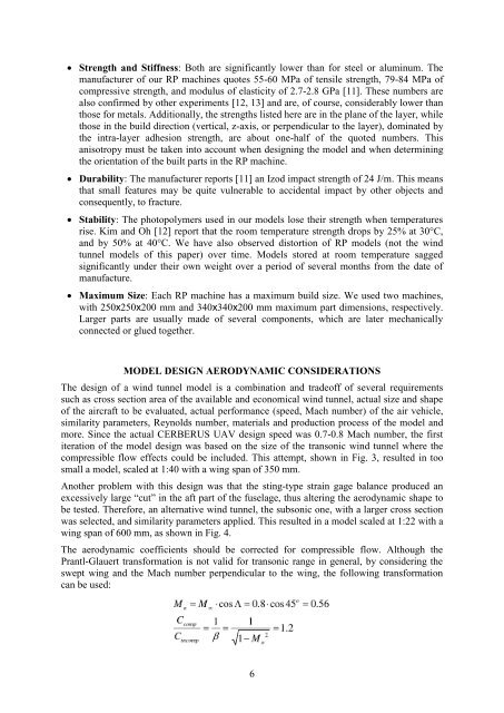
The <strong>aero</strong>dynamic coefficients should be corrected for <strong>com</strong>pressible flow. Although the<br />
Prantl-Glauert transformation is not valid for transonic range in general, by considering the<br />
swept wing and the Mach number perpendicular to the wing, the following transformation<br />
can be used:<br />
6


