Corrugated Wood Composite Panels For Structural Decking
Corrugated Wood Composite Panels For Structural Decking
Corrugated Wood Composite Panels For Structural Decking
Create successful ePaper yourself
Turn your PDF publications into a flip-book with our unique Google optimized e-Paper software.
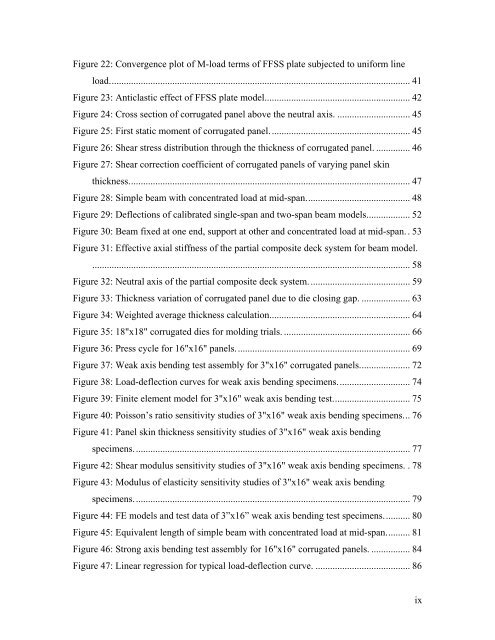
Figure 22: Convergence plot of M-load terms of FFSS plate subjected to uniform lineload............................................................................................................................ 41Figure 23: Anticlastic effect of FFSS plate model............................................................ 42Figure 24: Cross section of corrugated panel above the neutral axis. .............................. 45Figure 25: First static moment of corrugated panel.......................................................... 45Figure 26: Shear stress distribution through the thickness of corrugated panel. .............. 46Figure 27: Shear correction coefficient of corrugated panels of varying panel skinthickness.................................................................................................................... 47Figure 28: Simple beam with concentrated load at mid-span........................................... 48Figure 29: Deflections of calibrated single-span and two-span beam models.................. 52Figure 30: Beam fixed at one end, support at other and concentrated load at mid-span.. 53Figure 31: Effective axial stiffness of the partial composite deck system for beam model.................................................................................................................................... 58Figure 32: Neutral axis of the partial composite deck system.......................................... 59Figure 33: Thickness variation of corrugated panel due to die closing gap. .................... 63Figure 34: Weighted average thickness calculation.......................................................... 64Figure 35: 18"x18" corrugated dies for molding trials. .................................................... 66Figure 36: Press cycle for 16"x16" panels........................................................................ 69Figure 37: Weak axis bending test assembly for 3"x16" corrugated panels..................... 72Figure 38: Load-deflection curves for weak axis bending specimens.............................. 74Figure 39: Finite element model for 3"x16" weak axis bending test................................ 75Figure 40: Poisson’s ratio sensitivity studies of 3"x16" weak axis bending specimens... 76Figure 41: Panel skin thickness sensitivity studies of 3"x16" weak axis bendingspecimens.................................................................................................................. 77Figure 42: Shear modulus sensitivity studies of 3"x16" weak axis bending specimens. . 78Figure 43: Modulus of elasticity sensitivity studies of 3"x16" weak axis bendingspecimens.................................................................................................................. 79Figure 44: FE models and test data of 3”x16” weak axis bending test specimens........... 80Figure 45: Equivalent length of simple beam with concentrated load at mid-span.......... 81Figure 46: Strong axis bending test assembly for 16"x16" corrugated panels. ................ 84Figure 47: Linear regression for typical load-deflection curve. ....................................... 86ix


