Wideband Amplifiers
Wideband Amplifiers
Wideband Amplifiers

Create successful ePaper yourself
Turn your PDF publications into a flip-book with our unique Google optimized e-Paper software.
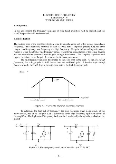
ELECTRONICS LABORATORYEXPERIMENT 6WIDE-BAND AMPLIFIERS6.1 ObjectiveIn this experiment, the frequency response of wide band amplifiers will be studied, and thecutoff frequencies will be determined.6.2 IntroductionThe voltage gain of the amplifiers that are used to amplify audio and video signals depends onfrequency. The frequency response of such a “wide-band” amplifier (Figure 6.1) has threeranges: mid frequency, low frequency and high frequency. The gain in low and high frequencyranges is lower than that of mid frequency range. The internal capacitances of the active devicesand the parasitic inductances lower the gain at high frequencies. The coupling capacitors andbypass capacitors cause the gain decrease as the frequency decreases.The mid-frequency range is determined by the 3-dB drop in the gain. At the low cut-offfrequency, the voltage gain is 3-dB lower than the mid-band gain. Likewise, high cut-offfrequency marks the 3-dB drop in the mid-band gain at the high frequency side.|Gain|3 dB———————————————low cut-off frequencyhigh cut-off frequencyfrequencyFigure 6.1 Wide-band amplifier frequency responseTo determine the high cut-off frequency, the high frequency small signal model of theactive device, BJT or FET (Figure 6.2), is substituted in the high frequency equivalent circuit ofthe amplifier. The high cut-off frequency is determined analytically through the analysis of thecircuit.(a)(b)Figure 6.2 High frequency small signal models: a) BJT b) FET— 6.1 —
(a)(b)(c)(d)Figure 6.3 a) Common emitter amplifier circuit, b) Mid-frequency equivalent circuit, c) Lowfrequencyequivalent circuit, d) High-frequency equivalent circuit— 6.3 —
Similarly, R THE , the Thevénin resistance seen by C E is not affected by C 2 . When C 1 isopen circuitWhen C 1 is short circuit:Rp+ rx+ rR THE = R E ||πβ + 1o(6.6)R THE = R E ||Rs Rp + rx+ r πβ + 1o(6.7)The Thevénin resistance seen by C 2 is found to beR TH2 = R C + R L (6.8)The pole frequency of each capacitor is found and compared with the other pole frequencies.Calculations may be repeated after the dominant capacitor is determined. The sum of all lowfrequencypoles will approximate the low 3-dB cut-off frequency.The high cut-off frequency of the amplifier may be found with the help of the equivalentcircuit in Figure 6.3d. In this circuit, the capacitor C µ is eliminated with Miller’s theorem. Thenew equivalent circuit is given in Figure 6.4. The capacitors that are connected parallel aretaken as one capacitor. The Thevénin resistances,R THA = r π ||(r x + R s ||R P ) (6.9)R THB = r o ||R C ||R L (6.10)and the high cut-off frequency1f H ≈2 π [( C + C ) R + C R ]A π THA B THB(6.11)C A ≈ C µ [1 + g m (r o ||R C ||R L )]; C B ≈ C µ [1 +1] ≈ C µg ( r R R)m o C LFigure 6.4 The application of the Miller’s Theorem to eliminate C µ in the common emitteramplifier high frequency equivalent circuit.— 6.4 —
When C E is open circuit:R TH1 = R P ||[ r π +(β o + 1) R E ] (6.15)When C E is short circuit:R TH1 = R P ||[ r π +( β o + 1) R E ||R s ] (6.16)The Thevénin resistance seen by C E is not affected by C 2 . Hence, when C 1 is opencircuit:Rp+R THE = R s + R E ||β + 1or π(6.17)When C 1 is short circuit:r πR THE = R s + R E ||β + 1o(6.18)Thevénin resistance seen by C 2 ,R TH2 = R C + R L (6.19)The pole frequency of each capacitor is calculated and compared with other pole frequencies.Once the dominant pole is determined, the non-dominant pole frequencies may be recalculated.The low cut-off frequency is estimated by adding all pole frequencies.The high cut-off frequency of the amplifier is found from the equivalent circuit in Figure6.5d. The application of the Miller’s theorem to this circuit brings lengthy calculations. Instead,the Thevénin resistances seen by C µ and C π are calculated directly:r πR THπ = R E ||R s ||β + 1o(6.20)R THµ = R C ||R L (6.21)Since the base of the transistor is connected to the ground, the Thevénin resistance seen by eachcapacitor is not affected by the other capacitor. The high cut-off frequency of the amplifier canbe estimated to bef H ≈12 π ( CR + CR )π THπ μ TH μ(6.22)— 6.6 —