INSTALLATION INSTRUCTIONS - Restoration Hardware
INSTALLATION INSTRUCTIONS - Restoration Hardware
INSTALLATION INSTRUCTIONS - Restoration Hardware

You also want an ePaper? Increase the reach of your titles
YUMPU automatically turns print PDFs into web optimized ePapers that Google loves.
<strong>INSTALLATION</strong> <strong>INSTRUCTIONS</strong>Showerhead forRH-6221 onlyMODEL: CampaignRH-6220RH-62211
<strong>Restoration</strong> <strong>Hardware</strong>Balance Pressure Tub /Shower SetSpecification DiagramShown with RH-212used in model RH-62212All Threaded Connections are 1 / 2” NPTDimensions are in Inches and Approximation of a Typical Installation
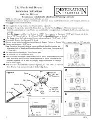
1.••PipeWrenchAdjustableWrenchInstallation InstructionsWe Recommend Installation by a Licensed Plumbing ProfessionalValve AssemblyPosition VALVE (1) with the “S” in the up positionCommon tools needed:PlumbersPuttyPipeCutterThe VALVES (1) 1/2 NPT inlets are colored blue for COLD SUPPLY(2) and red for HOT SUPPLY (3).VALVE (1) and / or SUPPLY (2,3) must be secured to CROSSBRACE (4) using PERFORATED STRAP (5) or equivalent.Secure TUB SUPPLY (7) to CROSS MEMBER (4) using PERFO-RATED STRAP (5) or equivalent.AssortedScrewdrivers•Apply thread sealant to the supply fittings and firmly tighten intoVALVE (1) inlets. Under normal soldering conditions the removal ofinlet filter/seat and mixing cartridge is not necessary; however, ifbrazing and / or induction heating is used, removal is required.Whenever possible, it is best to perform all solder/brazing operationson piping prior to attachment to VALVE (1).••Position VALVE (1) to finished wall as mentioned on specificationdiagram.•Apply thread sealant to SHOWER RISER (6) and attach to VALVE(1) outlet port marked “S”.•Secure SHOWER RISER (6) to CROSS MEMBER (4) using PER-FORATED STRAP (5) or equivalent.•Apply thread sealant to TUB SUPPLY (7) and attach to VALVE (1)outlet port marked “T”.••ThreadSealantApply PLUG (8) for test. Turn on both water supplies to valve andcheck for leaks. Note: Water pressure must be applied to both hot and cold inlet ports for proper valveoperation.•After inspection turn off water supply57836PerforatedStrap andClamp2143
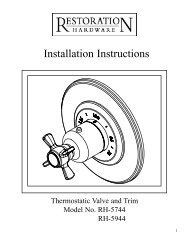
2.•Setting The Temperature Limit StopRemove the all-thread NIPPLE (1) and RETAIN-ING SCREWS (2) RETAINING PLATE (4) andSTEM (5) from the valve COVER (9).Remove the LIMIT STOP (6) see figure 2. Do notremove the MECHANICAL STOP (7). (If for anyreason the MECHANICAL STOP (7) is removedrefer to Cartridge Removal and Replace sectionbelow.)From the CLOSED position, rotate the CAR-TRIDGE STEM (10) counter-clockwise until thedesired temperature is achieved.Place the LIMIT STOP (6) on the CARTRIDGESTEM (10) against the STOP BLOCK (15) locatedon COVER (9). Rotate the CARTRIDGE STEM(10) several times to make sure the stop is at thedesired temperature setting.Replace the STEM (5), RETAINING PLATE (4)and RETAINING SCREWS (3) and all-thread NIP-PLE (1) onto valve COVER (9). (NOTE: For stem••••4to be fully seated into cartridge, all-thread nipple and locking nut must be tightly secured against retainingplate.)Proceed to the VALVE TRIM <strong>INSTALLATION</strong>.•2a.•••Cartridge Removal And ReplacementRemove the all-thread NIPPLE (1), RETAINING SCREWS(3), RETAINING PLATE (4) and STEM (5) from the valveCOVER (9).Remove the LIMIT STOP (6) and MECHANICAL STOP (7)Remove the COVER SCREWS (8), COVER (9) and coverO-RING (10).Carefully slide the CARTRIDGE (10) out of valve BODY(13). (If filter removal is necessary refer to Cleaning theFilter described in Trouble Shooting Section.)Replace CARTRIDGE (10) ensuring that the cartridge’s O-RINGS (11) are in place and lubricated with plumbers (nonpetroleum)grease. The “H” and “C” on the side of the CAR-••••TRIDGE (10) indicate the cartridges proper orientation to the appropriate inlet supply line.Once the CARTRIDGE (10) is installed, it is very important to confirm that the cartridges rear posts arecorrectly locked into the BODY (13) mating hole.Replace the cover O-RING (12), COVER (9) and tighten COVER SCREWS (8) firmly into place.To set the MECHANICAL STOP (7) rotate clockwise the CARTRIDGE STEM (10) until it stops.Warning: Do Not forcefully rotate stem closed.Place the MECHANICAL STOP (7) onto CARTRIDGE STEM (10) as shown in figure 1.Replace LIMIT STOP (6) as described above in Setting the Temperature Limit Stop.3167298 1045LIFT OFFLIMIT STOP.11 12 131514ROTATE SPLINE OFCARTRIDGE COUNTER-CLOCKWISE TO DESIREDMAXiMUM TEMPERATURE.PLACE LIMIT STOP (6)ON SPLINE AGAINSTSTOP BLOCK (15).LIMIT STOP (6) HITSSTOP BLOCK (15)AT HIGHEST DESIREDTEMPERATURE.
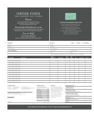
3. Valve Trim Installation(Perform these steps after finished wall has been completed)••••••The STEM (3) must be trimmed to 3-7/16” from finished wall. Remove STEM (3) by loosening NUT (2)and removing NIPPLE (1), NUT (2) and STEM (3). Trim STEM (3) to previously mentioned dimension.The NIPPLE (1) must be trimmed to 1-13/16” from finished wall or 1-5/8” less than STEM (3).Fasten STEM (3) and NIPPLE (1) onto VALVE (4). Use NUT (2) to lock NIPPLE (1) into place. RotateSTEM (3) to ensure there is no binding. If binding, loosen NIPPLE (1) until STEM (3) moves freely anddoes not wobble.Place diverter trim LINK (6) and POST (7) onto valve’s DIVERTER (5).Tighten diverter trim SLEEVE (9) onto DIVERTER (5).Align cover PLATE (8) and slide onto valve NIPPLE (1) and diverter SLEEVE (9). (Soapy water willimprove sliding of rubber seal onto diverter sleeve.)•Place ESCUTCHEON (11), BONNET (12) onto NIPPLE (1) and secure HANDLE (13) to STEM (3) withSCREW (14). Any adjustments for rotational alignment must be made by tightening cartridge. DO NOTloosen cartridge. Factory torque of 14 ft.lbs. must be maintained.•Place CAP (15) on HANDLE (13).•Tighten diverter KNOB (10) onto POST (7).1241211313141559761085
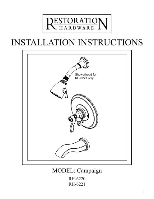
4.•Tub Spout InstallationPlace base RING (2) onto bottom of SPOUT(1).Based on finished wall thickness select appropriatesize 1/2” NPT NIPPLE (3) for SPOUT•(1) installation.Note: NIPPLE (3) is not included.123•Apply thread sealant to both ends of NIPPLE(3) and thread into fitting inside finished wall.•Attach SPOUT (1) to protruding NIPPLE (3)and secure into place.5.Showerhead InstallationFor RH-6221, available in catalog and on web only, (Balanced pressure tub and shower with SpeakmanUltra Showerhead kit.)•Slide SHOWER ARM (2) through the FLANGE (3).•Apply thread sealant to both ends of ARM (2) andthread into fitting inside finished wall.1•Turn on water supply, check for leaks and make anyfinal adjustments required.•Open valve and flush both shower and bath lines ofdebris.•••Slide FLANGE (3) against wall.Attach SHOWERHEAD (1) to end of ARM (2).Reattach stream STRAIGHTENER (4) to SPOUT (1).236
6.Test Installed Tub / Shower Set•Turn on the shower valve by rotating the handle counter-clockwise.Water will start to flow from the tub spout.•Pull the diverter knob to operate the showerhead.•Water mixing temperature to handle rotation is as follows:• 0 to 1/4 = cold • 1/4 to 1/2 = warm • 1/2 to 3/4 = hot7.Trouble Shooting* WARNING: At no time try to stop dripping by applying extreme force or overtightening the handle.7
Care and CleaningThe lustrous finish on your <strong>Restoration</strong> <strong>Hardware</strong> Bathware fixture shouldbe treated with care. Improper handling or cleaning can damage the surfaceof any metal finish. Use a soft cloth to wipe clean. Avoid harsh abrasivecleaner. Water contains lime and other mineral deposits that will be left onthe surface after the water has evaporated. You can prevent these depositsfrom forming by always wiping the fixture dry immediately after use.Technical Support and Customer ServiceFor technical support in the installation of your <strong>Restoration</strong> <strong>Hardware</strong>Bathware fixture, please call 1-866-417-5207 weekdays between the hoursof 7:00am and 4:00pm PST.For other questions regarding your order, to order additional components ofthe <strong>Restoration</strong> <strong>Hardware</strong> Bathware Collection, to order replacement parts,or to address warranty issues, please contact <strong>Restoration</strong> <strong>Hardware</strong>Customer Service at 1-877-747-4671.8
alance-pressures h o w e r s y s t e m sbalance-pressure valvesf e at u r e s & b e n e f i t s• Solid brass components.• Balance-Pressure feature ensures a constanttemperature despite changes in water pressure.• Five gallons/minute flow rate, sufficient tooperate one water outlet at a time.• Includes all attendant trim to coordinate withselect bath fittings collections.Other Components (sold separately):• Multi-Port Diverter Valve & Trim Set- Directs water to flow to oneof up to three water outlets.- Does not support more thanone outlet running at a time.Shower Onlyparts required• BP shower valve & trim set• Showerhead, flange & armTub & Shower Onlyparts required• BP tub & shower valve & trim set• Showerhead, flange & armShower &Handheld Showerparts required• BP shower valve & trim set• Showerhead, flange & arm• Handheld shower• Multi-Port Diverter Valve & Trim setTub & Shower withHandheld Showerparts required• BP tub & shower valve & trim set• Showerhead, flange & arm• Handheld shower• Multi-Port Diverter Valve & Trim set