EE 3323 Electromagnetics Laboratory
EE 3323 Electromagnetics Laboratory
EE 3323 Electromagnetics Laboratory

Create successful ePaper yourself
Turn your PDF publications into a flip-book with our unique Google optimized e-Paper software.
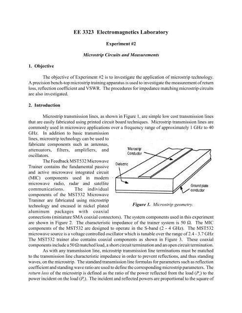
<strong>EE</strong> <strong>3323</strong> <strong>Electromagnetics</strong> <strong>Laboratory</strong>Experiment #2Microstrip Circuits and Measurements1. ObjectiveThe objective of Experiment #2 is to investigate the application of microstrip technology.A precision bench-top microstrip training apparatus is used to investigate the measurement of returnloss, reflection coefficient and VSWR. The procedures for impedance matching microstrip circuitsare also investigated.2. IntroductionMicrostrip transmission lines, as shown in Figure 1, are simple low cost transmission linesthat are easily fabricated using printed circuit board techniques. Microstrip transmission lines arecommonly used in microwave applications over a frequency range of approximately 1 GHz to 40GHz. In addition to basic transmissionlines, microstrip technology can be used tofabricate components such as antennas,attenuators, filters, amplifiers, andoscillators.The Feedback MST532 MicrowaveTrainer contains the fundamental passiveand active microwave integrated circuit(MIC) components used in modernmicrowave radio, radar and satellitecommunications. The individualcomponents of the MST532 MicrowaveTraniner are fabricated using microstriptechnology and encased in nickel platedaluminum packages with coaxialFigure 1. Microstrip geometry.connections (miniature SMA coaxial connectors). The system components used in this experimentare shown in Figure 2. The characteristic impedance of the trainer system is 50 Ù. The MICcomponents of the MST532 are designed to operate in the S-band (2 - 4 GHz). The MST532microwave source is a voltage controlled oscillator which is tunable over the range of 2.4 - 3.7 GHzThe MST532 trainer also contains coaxial components as shown in Figure 3. These coaxialcomponents include a 50 Ù matched load, a short circuit termination and an open circuit termination.As with any transmission line, microstrip transmission line terminations must be matchedto the transmission line characteristic impedance in order to prevent reflections, and thus standingwaves, on the microstrip. The standard transmission line formulas for parameters such as reflectioncoefficient and standing wave ratio are used to define the corresponding microstrip parameters. Thereturn loss of the microstrip is defined as the ratio of the power reflected from the load (P r) to thepower incident on the load (P ). The incident and reflected powers are proportional to the square ofi
2 2the voltages associated with the incident and reflected waves (V i and V r ). Return loss is normallyexpressed in units of dB such that(1)where à is the microstrip reflection coefficient.Figure 2. MST532 Microwave Trainer system components.
Figure 3. MST532 Microwave Trainer coaxial components.3. Equipment ListFeedback MWT532 Microstrip TrainerDC Power SupplyMultimeter4. Procedure4.1 Measurement of Return Loss1. Set up the system shown in Figure 4 with the short circuit coaxial termination, SC, denotedby a white spot on its casing, connected to point X, port 2 of the directional coupler. Connecta coaxial matched termination (MT) to port 3 of the directional coupler and connect thecrystal detector (D) to port 4 of the directional coupler. Connect the output of the detectorto the multimeter using a coaxial cable (to the to measure the detector DC output voltage).Port 2 of the circulator is connected to port 1 of the directional coupler using the SMA plugto plug connector (PPG). Connect a coaxial matched termination (MT) to port 3 of the
circulator. The operation of the directional coupler is a follows.A fraction of the microwave energy entering port 1 exits port 3.(power out of port 4 is negligible)A fraction of the microwave energy entering port 2 exits port 4.(power out of port 3 is negligible)The circulator can be used as an isolation device. The basic operation of the circulator, asthe names implies, is to direct microwave energy in different directions as follows.Microwave energy entering port 1 exits port 2.Microwave energy entering port 2 exits port 3.Microwave energy entering port 3 exits port 1.By connecting the circulator as shown in Figure 4, with a matched termination on port 3, thecirculator is used as an isolation device. All of the microwave energy entering port 1 passesthrough the circulator out port 2. Any reflected energy entering port 2 is directed to port 3,where it is absorbed by the matched termination. Thus, the circulator is providing isolationfor the microwave source (VCO - voltage controlled oscillator) connected to port 1 of thecirculator.Figure 4. Experimental setup for return loss measurements.The VCO requires 3 input connections from two DC power supplies. The negative terminalsof the DC power supplies should be connected together and then connected to the groundinput to the VCO (black). One DC power supply should be set to +15V and its positiveterminal connected to the power input terminal (red) of the VCO. The positive terminal ofthe other DC power supply serves as the tuning voltage and should be connected to thetuning voltage input to the VCO (white). Set the modulator switch on the VCO to OFF.2. Measure the reflected power coupled out of the directional coupler at port 4 at frequenciesof 2.4, 2.5, 2.75, 3.0 and 3.25 GHz. The value of tuning voltage required for each frequencyis obtained from the supplied VCO calibration curve. The measured crystal detector outputvoltage can be translated to microwave output power using the calibration curve for thedetector.3. Disconnect the short circuit termination and replace it with the open circuit termination, OC,
denoted by a blue spot on its casing. Repeat the reflected power measurements of part 2.4. Determine the average value of the measured reflected powers for the short circuit and opencircuit loads at each frequency. This average value represents the incident power at eachfrequency.5. Disconnect the open circuit and connect the microstrip matched load (ML). You will needa plug to plug connector (PPG) to connect the matched load to the directional coupler.Measure the reflected power at port 4 of the directional coupler for the five frequencies usedin part 2.6. Disconnect the microstrip matched load and connect a 50 Ù coaxial termination at point X.Measure the reflected power at each of the five frequencies.7. Disconnect the 50 Ù coaxial termination and connect the low pass filter at point X using aplug to plug connector (PPG). Terminate the filter output with a 50 Ù coaxial termination.Measure the reflected power at each frequency from 2.45 to 3.65 GHz in 50 MHz steps.From your measured results, calculate the reflection coefficient, the return loss in dB, andthe standing wave ratio for the three components investigated (microstrip matched load, coaxialmatched load, low pass filter). Compare the characteristics of the microstrip and 50 Ù coaxialmatched terminations. Estimate the cutoff frequency of the low-pass filter based on your measuredresults.4.2 Matching Measurements1. The same experimental setup used for the return loss measurements will be used for thematching measurements (Figure 4) except the unit containing an unknown load, a ë/4transformer and a shunt stub tuner (ZT) will be used. Set up the system shown in Figure 4with the short circuit coaxial termination, SC, denoted by a white spot on its casing,connected to point X, port 2 of the directional coupler. Measure the reflected power coupledout of the directional coupler at port 4 at frequencies of 2.7 to 3.3 GHz in 100 MHz steps.2. Disconnect the short circuit termination and replace it with the open circuit termination, OC,denoted by a blue spot on its casing. Repeat the reflected power measurements of part 1.3. Determine the average value of the measured reflected powers for the short circuit and opencircuit loads at each frequency. This average value represents the incident power at eachfrequency.4. Disconnect the open circuit and connect the line A (the unknown resistive load R) of thematching unit (ZT). Measure the reflected power at port 4 of the directional coupler for thefrequencies used in part 1.5. Disconnect line A and connect line B (the ë/4 wave transformer) at point X. Measure thereflected power at each of the frequencies used in part 1.6. Disconnect line B and connect line C (the shunt stub tuner) at point X. Measure the reflectedpower at each of the frequencies used in part 1.From your measured results, calculate the reflection coefficient and standing wave ratio forthe unknown load resistance termination. From the reflection coefficient, determine the value of theunknown load R. Perform these calculations at each of the measured frequencies. Also, calculate
the reflection coefficient and standing wave ratio for the ë/4 wave transformer and the shunt stubtuner at each frequency. Plot graphs of the measured standing wave ratio vs. frequency for the threeterminations and discuss your results.