Create successful ePaper yourself
Turn your PDF publications into a flip-book with our unique Google optimized e-Paper software.
HQ210<strong>User</strong> <strong>Manual</strong>Quested Monitoring Systems
Table of Contents1. Introduction . . . . . . . . . . . . . . . . . . . . . . . . . . . . . . . . . . . . . . . . . . . . . . . . . . . . . . .32. Safety considerations2.1 General . . . . . . . . . . . . . . . . . . . . . . . . . . . . . . . . . . . . . . . . . . . . . . . . . . . . . .42.2 Hearing damage . . . . . . . . . . . . . . . . . . . . . . . . . . . . . . . . . . . . . . . . . . . . . . .43. Unpacking . . . . . . . . . . . . . . . . . . . . . . . . . . . . . . . . . . . . . . . . . . . . . . . . . . . . . . . .44. Installation . . . . . . . . . . . . . . . . . . . . . . . . . . . . . . . . . . . . . . . . . . . . . . . . . . . . . . . .54.1 Positioning . . . . . . . . . . . . . . . . . . . . . . . . . . . . . . . . . . . . . . . . . . . . . . . . . . .55. Audio connections . . . . . . . . . . . . . . . . . . . . . . . . . . . . . . . . . . . . . . . . . . . . . . . .75.1 Definitions . . . . . . . . . . . . . . . . . . . . . . . . . . . . . . . . . . . . . . . . . . . . . . . . . . .75.2 Passive Operation . . . . . . . . . . . . . . . . . . . . . . . . . . . . . . . . . . . . . . . . . . . . .85.3 Bi-Amped Operation . . . . . . . . . . . . . . . . . . . . . . . . . . . . . . . . . . . . . . . . . .105.4 Tri-Amped Operation . . . . . . . . . . . . . . . . . . . . . . . . . . . . . . . . . . . . . . . . . .105.5 2 Way Active . . . . . . . . . . . . . . . . . . . . . . . . . . . . . . . . . . . . . . . . . . . . . . . . .115.5.1 Converting from passive if speakers are free standing . . . . . . . . . . . . . . . .115.5.2 Converting from passive if speakers are soffit mounted . . . . . . . . . . . . . . .115.6 3 Way Active . . . . . . . . . . . . . . . . . . . . . . . . . . . . . . . . . . . . . . . . . . . . . . . . .125.6.1 Converting from passive or bi-amped if speakers are free standing . . . . . . .125.6.2 Converting from passive or bi-amped if speakers are soffit mounted . . . . . .125.7 Cable . . . . . . . . . . . . . . . . . . . . . . . . . . . . . . . . . . . . . . . . . . . . . . . . . . . . . . . .126. Technical specification . . . . . . . . . . . . . . . . . . . . . . . . . . . . . . . . . . . . . . . . . . . .137. Line Drawing . . . . . . . . . . . . . . . . . . . . . . . . . . . . . . . . . . . . . . . . . . . . . . . . . . . . . .148. Guarantee . . . . . . . . . . . . . . . . . . . . . . . . . . . . . . . . . . . . . . . . . . . . . . . . . . . . . . . .159. Appendix . . . . . . . . . . . . . . . . . . . . . . . . . . . . . . . . . . . . . . . . . . . . . . . . . . . . . . . . .159.1 Accessories . . . . . . . . . . . . . . . . . . . . . . . . . . . . . . . . . . . . . . . . . . . . . . . . . . .159.2 Spares . . . . . . . . . . . . . . . . . . . . . . . . . . . . . . . . . . . . . . . . . . . . . . . . . . . . . . .159.3 Driver replacement procedure . . . . . . . . . . . . . . . . . . . . . . . . . . . . . . . . . . . .169.3.1 Tweeter & tweeter diaphragm . . . . . . . . . . . . . . . . . . . . . . . . . . . . . . . . . .169.3.2 Mid range driver . . . . . . . . . . . . . . . . . . . . . . . . . . . . . . . . . . . . . . . . . . .179.3.3 Bass Driver . . . . . . . . . . . . . . . . . . . . . . . . . . . . . . . . . . . . . . . . . . . . . . . .17
1. IntroductionThank you for purchasing your Quested product and whether it is a pair of passive monitors or a4 way active system you can be assured the same care has gone into its design and manufacture.You can be sure you have purchased one of the finest monitors in the world and if you take timeand care in positioning and aligning the system you will appreciate why Quested monitors havea reputation for faithful reproduction covering the entire audible spectrum. They are professionalmonitors, and are not designed to flatter, but faithfully reproduce. Please take care to maintainthe system and you will obtain many years of servicePlease take the trouble to complete the registration form that came with your monitors. This willhelp us in the future, should you raise any queries. If you have any questions please addressthem to your Quested representative, who will then refer back to the designer and manufacturerif necessary. In this way, you will be assured in obtaining the best possible performance and longterm reliability of your system.This manual covers the HQ210 3 way passive monitor.Please read this manual, which we have kept as concise as possible, it really will help you andcovers important safety considerations.The HQ210 is a 3 way passive monitor that can be used soffit mounted or free standing and theability to rotate the mid/hi baffle enables the speaker to be installed in a horizontal or verticalorientation. They are suitable for use as main monitors in mid sized control rooms or as mid fieldreference monitors in large rooms.Typical applications include post production suites, broadcast, project studios, surround sound,mastering suites and main monitors in medium sized control rooms.The HQ210 monitors can be run passively with the ability to bi or tri-wire and can also be run bior tri-amped. They also have the ability to be run 2 way or 3 way active but will need the additionof an external electronic crossover, and to take advantage of the additional power that willbe available some of the drivers should be upgraded.A pair of HQ210 are ideally driven by a Quested AP800 amplifier, but other amplifiers with apower output of between 200-700 watts RMS per channel can be used.The low frequency performance is more than adequate for most situations, but can be furtherextended by combining it with the VS1115 15” sub bass to extend the frequency response downto 20Hz. The VS1115 is also ideal when a discrete sub channel is required when using formatssuch as Dolby 5.1Page 3
2. Safety Considerations2.1 GeneralTHE HQ210 HAS BEEN DESIGNED IN ACCORDANCE WITH INTERNATIONAL SAFETY STANDARDS.THE FOLLOWING WARNINGS MUST BE FOLLOWED TO ENSURE SAFE OPERATION OF THIS EQUIP-MENT.CAUTION:THIS UNIT CONTAINS MAGNETIC COMPONENTS WHICH MAY EFFECT ADJACENTSUSCEPTIBLE EQUIPMENT.2.2 Hearing DamageThis equipment can deliver sound pressure levels in excess of 112dB. At this level permanent hearingdamage can occur and exposure to this level of sound, even for relatively short periods (seetable below), can be harmful. Of equal importance to the maximum level of sound is the exposureto high levels of sound for extended periods. There are no international agreed limits and differentcountries have different limits measured in differing ways. IT ISTHEREFORE IMPORTANT THAT THE USERESTABLISHES THE RECOMMENDED, AND IN SOME TERRITORIES, LEGAL LIMITS, THAT ARE IN PLACE.As a guide the table below shows the levels that are acceptable in the majority of Western Europeand the US & Canada.SPL dB(A) Listening time per day90 8 hours95 2.4 hours100 40 minutes105 15 minutes110 5 minutes115 and over Not at allIt is also important to note that the effect of exposure to sound is cumulative. Having listenedto sound, for example, for 15 minutes at 105 dB then further exposure to noise levelsabove 80dB should be avoided until the next day.3. UnpackingThis Quested product has been carefully manufactured, tested and packed to ensure it arrives in aflawless condition. The component parts of the packing have been thoughtfully designed to offer sufficientprotection during transportation, yet remain fully recyclable and should be retained for futureuse.Page 4
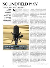
4. Installation4.1 PositioningThe HQ210 is designed to be mounted either horizontally or vertically, but it is important thatthe baffle containing the mid range and the tweeter are correctly aligned as indicated in the diagrambelow.HQ210 mountedhorizontallyHQ210 mountedVerticallyNote the baffle is taken out and turnd through 90 degrees when thecabinet is changed from vertical to horizontal mounting so that thethe tweeter and mid range are still aligned vertically.The HQ210 can either be soffit mounted or positioned on speaker stands, but which ever way ischosen, the support should be rigid and must not vibrate when the monitor is driven. Vibrationswill result in lack of low frequency definition. Its positioning close to or away from the rear walland proximity to any room corners is best determined by experimenting and placing the speakerin differing positions. The shape of the room, normal listening position and room treatment willall have an effect on determining the speakers positioning.Placing the cabinet against a wall will reinforce the bass performance of the speaker and up toan additional 3dB may be obtained. Placing the monitors in a corner will further reinforce thebass performance and gains of up to 6dB may be achieved, but be very careful about siting themonitors in a room corner because it can excite standing waves and create an unpleasantboominess.The speakers should be positioned so that the axis (an imaginary line drawn from the acousticcentre of the left and right monitor — see line drawing on page 14 of this manual) should crossbetween 0.5 and 1 meter behind the engineers position, for the following reasons:-a) To obtain the most accurate imaging, both front to rear and side to side, and to obtain aslarge as possible listening area so that the engineer can move and operate the console withoutperceiving a change in character of the monitors.b) To enable listening for long periods of time without suffering strain or fatigue.Page 5
Sketch showing positioning of speakers. The speakers should be between 2.5 - 3.4 meters apart and the axis ofthe speakers should cross between 0.5 and 1 meter behind the listening position2.5 - 3.4 mtrsThe height of mounting the speaker is equally as important. The correct height should result in the axisbeing at ear level when the engineer is sitting in his normal position at the console.Page 6
5 Audio ConnectionsThe connection to the HQ210 is through a triple pair terminal tray which accepts either bare endcables or 4mm banana plugs. Each pair of terminals corresponds to individual sets of drivers andare marked accordingly with Hi, Mid & Lo.|+HiMidLo5.1 DefinitionsThe terms tri-wired, bi-amped etc. can be confusing as they are not always used consistently, so thefollowing definitions indicate the meaning as used in this manual.Passive One amplifier channel is used for all the monitor drive units. An internal passive crossoverseparates the programme frequencies and directs them to the appropriate drive units. On theHQ210 the input to each section of the internal crossover is available on separate terminal connectionsto facilitate a number of different wiring options.Bi-wired This is a wiring option when running the monitors in the passive mode. Here the singlechannel amplifier has a pair of twin cables running between its output terminals and the input terminaltray of the monitor. Generally the bass driver would be driven from one cable and the midand high drivers together from the other cable. Tri-Wired This is a wiring option when running themonitors in the passive mode. Here the single channel amplifier has 3 twin cables running betweenits output terminals and the input terminal tray of the monitor. Each set of drive units (bass, mid &high) in the monitor will be run from its own cable.Bi-Amped 2 amplifier channels are used for each monitor. One amplifier channel will drive thebass, the other the mids & highs together. Both channels will use the internal passive crossover,therefore this is not the same as running the speakers 2 way active where the bass would be drivendirectly from the amplifier without the signal passing through the internal crossover.Page 7
The mid and high would use a separate amplifier channel with the mid being driven directly fromthe amplifier and the high through the internal passive crossover. This method of running the monitorswould require the use of an external electronic crossover.Tri-Amped 3 amplifier channels are used for each monitor. One amplifier channel will drive thebass, another the mids and the 3rd the highs. All channels will use the internal passive crossover,therefore this is not the same as running the speakers 3 way active where each set of drive units(bass, mid & high are driven directly from the amplifier without the signal passing through theinternal crossover. This method of running the monitors would require the use of an external electroniccrossover.5.2 Passive operationWhen run passively the the programming plug on the passive crossover circuit boardmust be plugged into the socket CN3, marked as passive. This is how the speaker is set up atthe time of shipment from the factory when supplied as passive. See page 11 & 12 on changingthe position of the programming plug if converting the speaker to passive from 2 or 3 way active.These monitors can either be installed with a single twin cable, 2 twin cables (bi-wired) or 3 twincables (tri-wired). It is recommended that the monitors are installed bi or tri-wired. This will makea small improvement in sound quality by minimising distortions produced by voltage losses associatedwith the interaction of signal currents flowing through the loudspeaker cables. If the speakersare to be soffit mounted and there is any intention to convert to bi or tri-ampedoperation then the speakers should be bi or tri-wired to avoid the need to remove thespeakers from their soffit mounting position when converting.If installing with a single twin cable the hot or positive wire should be connected to the appropriateterminal marked (+) and having the red marking round the screw down knob. The cold or negativewire should be connected to the corresponding terminal marked (-) and having the blackmarking round the screw down knob. The brass connecting links between the 3 (+) terminals andthose linking the 3 (-) terminals, should remain in place.Passive operation: The connection from the amplifier can beto any of the terminals, but the connecting links must be keptin place. The hot or positive wire to the terminal marked (+) red.and the cold or negative wire should be connected to theterminal marked (-) black.orAMPLIFIERorAll links remain in placePage 8
If the speakers are to be bi-wired there will be a pair of twin cables from the amplifier. One twincable should be connected to the terminal marked lo and the links between it and the terminalsmarked mid should be removed. The other cable can be connected to either the terminals markedMid or Hi, but the links must remain in place. With both twin cables the hot or positive wireshould go to the (+) terminals and the cold or negative wire to the (-) terminals.HiorPassive operation, but with bi-wired connection. A pair of twin cablesis run from the amplifier. One wire should be connected to the terminalmarked Lo and the links between Lo & Mid should be removed.The other wire can be connected to either the terminal marked Mid or Hibut links must remain in place. With both the twin cables the hot or positivewire should go to the (+) red terminal and the cold or negative wire to the(-) black terminal.MidAMPLIFIERandLoLinks between Lo & Mid removedIf the speakers are to be tri-wired there will be 3 twin cables from the amplifier. The hot or positivecables should be connected to the 3(+) terminals and the cold or negative cables to the 3(-)terminals and all the connecting links removed.HiPassive operation, but with tri-wired connection : 3 twin cables are run fromthe amplifier. One wire should be connected to the terminal marked Lo, thesecond to the terminal marked mid and the final wire connected to the terminalmarked Hi. All links should be removed. The hot or positve wire should go tothe (+) red terminal and the cold or negative wire to the (-) black terminal.MidAMPLIFIERLoAll links removedPage 9
5.3 Bi-Amped OperationIf the speakers are to be run bi-amped 2 amplifier channels will be used to drive each monitor.One amp channel should be connected to the either the terminal marked Mid or Hi and the linkbetween these terminals kept in place. Another channel should be connected to the terminalmarked Lo and the links between the mid and lo terminals should be removed.Bi-amped operation will allow the use of two lower powered amps, rather than a single high poweredamp when the HQ210 is driven passively, so might be useful when upgrading from smallermonitors, or, for example, a specialist/esoteric valve amp. is required to drive the mid & hi drivers.5.4 Tri-Amped OperationAmplifier 1 should drive the mid & hi. The connection from this amplifier should be to eitherthe terminal marked Mid or Hi and the link between the terminals should be kept in placeAmplifier 2 will drive the lo. The connection from this amplifier should be to the terminalmarked Lo and the link between terminals marked Mid & Lo should be removed.With both twin cables the hot or positive wire should go to the (+) red terminal and the coldor negative wire to the (-) black terminal.HiAMPLIFIER 1orMidAMPLIFIER 2andLoLinks between Lo & Mid removedIf the speakers are to be run tri-amped 3 amplifier channels will be used to drive each monitor.One amp. channel should be connected to the terminal marked Hi, another channel should beconnected to the terminal marked Mid and the third channel should be connected to the terminalmarked Lo. All the links should be removed. The same comments regarding the use of lower powered/specialistamps as noted under bi-amped operation in the above paragraph applies.Amplifier 1 should drive the hi and the connection from this amplifier should be to the terminalmarked Hi. Amplifier 2 should drive the mid and the connection from this amplifier should be toterminal marked Mid. Amplifier 3 should drive the lo and the connection from this amplifier should be toterminal marked Lo. All terminal links should be removed. With the three twin cables the hot or positivewire should go to the (+) red terminal and the cold or negative wire to the (-) black terminal.HiAMPLIFIER 1MidAMPLIFIER 2AMPLIFIER 3LoAll links removedPage10
5.5 2 Way ActiveIf the monitors are shipped set up for bi-amped operation then the following connections should bemadeThe link connecting the terminals marked Lo & Mid for both the hot (+) and cold (-) should havebeen removed. The cable that runs from the amplifier/amplifier channel chosen to drive the bass driversshould be connected to terminals marked lo and the cable that runs from the amplifier/amplifierchannel chosen to drive the mid & high drivers should be connected to either of the terminalsmarked mid or high. Remember to leave the link connecting the mid and hi terminals inplace.unless the mid/high speakers are to be run bi-wired (separate cables for the mids & highs, butstill though the passive crossover) then the link should be removed and the cable run to both themid and hi terminals. In all cases the hot or positive cable should go to the terminal marked (+) andthe cold or negative cable to the terminal marked -).If the monitors are being converted from passive operation the following instructions should benoted.When the HQ210 is shipped direct from the factory the LS2500 (Quested part number Q01-0030)bass drivers are fitted. These drivers are capable of handling greater power and it is recommendedthat if you are converting passive monitors you also upgrade the bass drivers.Whether new drivers are fitted or not, it will be necessary to change the connection on the passivecrossover as follows:5.5.1 Converting from passive if the speakers are free standing:-a) Remove the six M5 countersunk socket screws that hold the terminal tray mounting board.b) Remove the complete assembly which contains the passive crossover, the wooden mountingboard and the terminal tray. Be careful not to put strain on the cables that run to the speakers.c) On the crossover circuit board, locate the programming plug CN2 which will be plugged intosocket CN3, marked as passive. Disconnect the programming plug by gripping the sides andpulling. Finally reconnect the plug into socket CN4, marked as ‘2 W-Active’d) Replace the complete assembly and screw back in place with M5 socket screws5.5.2 Converting from passive if the speakers are soffit mounted:-There will no need to remove the monitors as long as they have been bi or tri-wired as detailed in5.2 above.a) Remove the left hand bass driver by undoing the four M5 socket cap screws.b) Disconnect the crimp connectors noting colour coding of wiring to the loudspeaker terminals.c) Pull away the felt at the rear of the cabinet (this has been tack stapled so will be easy to pullaway). This will reveal the passive crossover.d) Repeat procedure as in 5.5.1 c) above.e) The felt should then be tacked back into place and the bass driver reconnected.Page 11
5.6 3 Way-ActiveIf the monitors are set up for 3 way-active operation then the following connections should bemade.All the links connecting the terminals should have been removed. The cable which runs from theamplifier chosen to drive the bass drivers should be connected to the terminals marked lo. Thecable running from the amplifier chosen to drive the mids should be connected to the terminalmarked as mid and the cable running from the amplifier chosen to drive the high frequency unitsshould be connected to the terminal marked hi.In all cases the hot or positive cable should go to the terminals marked (+) and the cold or negativecable to the terminals marked as (-).If the monitors are being converted from passive or bi-amped operation the following instructionsshould be noted.When the active monitors are shipped from the factory the following upgraded drivers are fitted tothe HQ210 Active.Bass Drivers - LS2500 (Quested part number Q01-0030)Mid Drivers - MD3SD (Quested part number Q02-0030)HF Units - TW34 (Quested part number Q03-0030)It is strongly recommended that if you are converting passive or bi-amped monitors you alsoupgrade the bass drivers to the LS2500 and fit a new mid/hi baffle containing the MD3SD andTW34.It will then be necessary to change the connection on the passive crossover.5.6.1 Converting from passive or bi-amped if the speakers are freestanding:-Repeat the procedure as in 5.5.1above, except reconnect the programming plug CN2 into socketCN5, marked as 3 way-active.5.6.2 Converting from passive or bi-amped if the speakers are soffitmountedThere will be no need to remove the monitors as long as they have been tri-wired as detailedabove.Repeat the procedure as in 5.5.2 above, except reconnect the programming plug CN2 into socketCN5, marked as 3 way-active.5.7 CableWhen running speaker cables it is important that good quality oxygen free cable (OFC) is used. Ifthe connection is with a single pair of cables 4mm 2 speaker cable should be used, with bi/tri wiredconnections, 2,0mm 2 cable should be run.Page 12
6. Technical SpecificationSize (w x h x d): 590 x 850 x 355mm ( 23” x 33” x 14”)Weight:Drivers:Maximum SPL:Sensitivity:Frequency Response:Nominal Impedance:Connectors:Crossover:Power requirements:60kgs (132lbs)Bass 2 x 254mm (10”) coneMid Range 1 x 75mm (3”) soft domeHigh Frequency 1 x 28mm(1 1 / 8 ”) soft dome112dB(C)91.5dB at 1 watt at 1 meter40Hz-18kHz ±2dB8ΩTriple pair gold plated binding posts for 4mm banana orbare wire allowing connection through the passivecrossover to the individual sets of driversMultipole network utilising polypropylene capacitors andair cored inductors throughout.Amplifier rating at 8ohm between 300-900 watts RMSThis product is built to conform to the requirements for CE markingPage 13
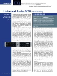
7. Line Drawing355.00 mm13.98 "590.00 mm23.23 "850.00 mm33.46 "Acoustic CentrePage 14
8. GuaranteeThe HQ210 is guaranteed for 24 months from its date of purchase. If any part of the product isfound defective due to faulty manufacture within 24 months from the date of purchase, Quested,through its authorised distribution network will effect repair or replacement, at its discretion, free ofcharge providing:-a) The fault is reported to the authorised distributor.b) Proof of purchase is provided.c) The fault is not caused by, misuse, neglect, or faulty operation by the user.d) The fault is not a result of fair wear & teare) The equipment has not been modified in any wayf) The equipment has not been taken apart or tampered with in any way other thandescribed in the service manual for the adjustment and replacement of user accessibleitems.The guarantee does not covera) Damage during transitb) Damage to diaphragms, cones and other speaker parts as a result of the over-driving ofthe monitors or by faulty installation or connection.c) Damage caused by incorrect installation or during installation caused by incorrect handling.d) The cost of carriage to or from the authorised repairer.9. Appendix9.1 AccessoriesAccessoryPart NumberTW30DMS Shielded Tweeter Q03-00119.2 SparesSpare part DescriptionPart NumberLS 2505mm (10”) Loudspeaker Q01-0035MD75D 3” midrange soft dome Q02-0040TW30 28mm (1 1 / 8 ”) soft dome Q03-0010RD30 28mm (1 1 / 8 ”) soft dome diaphragm Q53-0010RC2505 10” Loudspeaker recone Q50-0035Page 15
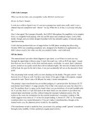
9.3 Driver replacement procedures9.3.1 Tweeter and tweeter diaphragmThe tweeter is held in by 3 self tapping wood screws. Remove these with a posidrive no. 2 screwdriver.Take out the tweeter and disconnect the two wires, noting which colour goes to which terminal.If on removing the 3 screws that hold the tweeter there is any difficulty in removing the unitdo not try to force a blade between the cabinet and tweeter, but use a small narrow bladed screwdriverin one of the screw holes to gently lever out the tweeter.a) Remove the 3 machine screws on the front plate of the tweeter using a 2mm hex driver.b) De-solder and unwind wires from the terminal tagsc) Remove diaphragm assembly and replace with the new diaphragm. The Ferrofluid hasthe appearance of oil and is dark brown in colour and should cover about 1/3 of thecoil. If there is less than this then additional Ferrofluid should be added. This can beobtained from your dealer/distributor or directly from Quested. The ferrofluid referenceisIt should be noted that ferrofluid is best added as shown in thediagram below. The fluid should never cover more than 1/2 the coil.d) Wrap the wires from the diaphragm around the corresponding tagse) Keep the wire slightly taught, but do not strainf) Re-solder the wires and re-assemble.Wire with curved loop formed at one end12FerrofluidTweeterDip wire in ferrofluid, a small amount will be retained on the wirehold wire over the tweeter gap and the magnet will attract thefluid from the wire into the gap. Do this 3 or 4 times in differentposition on the tweeter, then check by inserting the new diaphragmto see the amount of fluid in the tweeter.Page 16
9.3.2 Mid range driverNo recone kit that is available for the mid range so if a fault develops the unit will need to bereplaced.Remove the 4 self tapping wood screws using a posidrive no.2 screwdriver. Take out the unit anddisconnect the two wires, noting which colour goes to which terminal. If on removing the 4screws that hold the mid range there is any difficulty in removing the unit do not try to force ablade between the cabinet and mid range, but use a small narrow bladed screwdriver in one ofthe screw holes to gently lever out the unit.Connect the new mid range and re assemble into the cabinet. Do not overtighten the 4 screws.9.3.3 Bass driver and bass driver recone.The bass drivers are held in by four M5 machine screws. Remove the screws in the order shownbelow using a 4mm hex driver The drivers are heavy so hold the driver by the frame whenremoving the last screw. Remove the bassdriver, using a screwdriver in one of thescrew holes to gently lever out the driver13 if there is any difficulty in removing theunit. Do not force a blade between thecabinet and driver. Disconnect the twowires, noting which colour goes to whichterminal. Replace with the new driver andre-assemble in the reverse order.42A recone unit is available for the HQ210bass driver. Instruction for reconing isincluded with the recone kit. However,unless you are familiar with the practiceof reconing it is better to have the speakerreconed by someone who is experienced.Page 17