chapter 2. dosimetric principles, quantities and units - IRSN
chapter 2. dosimetric principles, quantities and units - IRSN
chapter 2. dosimetric principles, quantities and units - IRSN

Create successful ePaper yourself
Turn your PDF publications into a flip-book with our unique Google optimized e-Paper software.
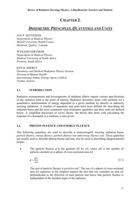
Chapter <strong>2.</strong> Dosimetric Principles, Quantities <strong>and</strong> Units• The mean excitation potential I is a geometric mean value of all ionisation <strong>and</strong>excitation potentials of an atom of the absorbing material. Since binding effectsinfluence the exact value of I, calculation models are often inadequate toaccurately estimate its value. Hence, I values are usually derived frommeasurements of stopping powers in heavy charged particle beams for which theeffects of scattering in these measurements is minimal.• For elemental materials I varies approximately linearly with Z, with, on average,I = 11.5 Z. For compounds I is calculated assuming additivity of the collisionstopping power taking into account the fraction by weight of each atomconstituent in the compound.• The following observations can be made from (Eq. (<strong>2.</strong>11)):- The mass stopping power does not depend on the projectile mass <strong>and</strong> isproportional to the inverse square of the projectile velocity. Note that theterm 2m ov 2under the logarithm has no relation with a kinetic energy of anyof the particles involved in the collision process.- The mass stopping power gradually flattens to a broad minimum for kinetic2energies KE ≅ 3mec.- The leading factor Z/A is responsible for a decrease of about 20% in stoppingpower from carbon to lead. The term − ln I causes a further decrease instopping power with Z.- The square dependence on the projectile charge (z 2 ) causes heavy chargedparticles with double the charge to have four times the stopping power.• For electrons <strong>and</strong> positrons, energy transfers due to soft collisions are combinedwith those due to hard collisions using the Moller (for electrons) <strong>and</strong> Bhabba (forpositrons) cross-sections for free electrons. The complete mass collisionalstopping power for electrons <strong>and</strong> positrons, according to ICRU Report 37, is:2 2Scol NAZπ ro 2mec2±= ⎡ln 2( KE / I ) + ln(1 + τ / 2) + F ( τ)−δ⎤ρ A β ⎣⎦with F−given for electrons asF= − + − +−2 2( τ) (1 β )[1 τ /8 (2τ1)ln2](<strong>2.</strong>12)<strong>and</strong> F+given for positrons asFτ = − β + τ + + τ + + τ + 3+2 2( ) 2ln 2 ( /12)[23 14 /( 2) 10 /( 2) 4 /( 2) ].2In this equation, τ = KE / m c <strong>and</strong> β = v / c .e42
Review of Radiation Oncology Physics: A H<strong>and</strong>book for Teachers <strong>and</strong> Students• δ is the density effect correction that accounts for the fact that the effectiveCoulomb force exerted on a fast charged particle by atoms that are distant fromthe particle track is reduced as a result of the polarization of the medium causedby the charged particle. The density effect affects the soft collision component ofthe stopping power. It plays a significant role in the values of ratios of stoppingpowers of a dense material to a non-dense material (such as, for example, water toair) <strong>and</strong> various models for it have been developed.• The mass radiative stopping power is the rate of energy loss by electrons orpositrons that results in the production of bremsstrahlung. The Bethe-Heitlertheory leads to the following formula for the mass radiative stopping power:SN Z2radA2σo( KE mec ) Bρ = A+ r(<strong>2.</strong>13)where( ) 22 2 −28 2σ = α e /(4 πε m c ) = 5.80× 10 cm /atom where α is the fine structureo o econstant, <strong>and</strong> B ris a function of Z <strong>and</strong> KE, varying between 5.33 <strong>and</strong> 15 forenergies in the range from less than 0.5 MeV to 100 MeV.This factor together with the increase of the radiative stopping power proportionalwith KE is responsible for the increase in total stopping power at energies above 2MeV as depicted in Fig. <strong>2.</strong><strong>2.</strong> Note that the Z 2 dependence of the mass radiativestopping power in contrast to the Z dependence of the mass collision stoppingpower makes this mode of energy loss more prominent in high-Z materials.• The concept of restricted mass collision stopping power is introduced to calculatethe energy transferred to a localized region of interest. By limiting the energytransfer to secondary charged (delta) particles to a threshold (often denoted as ∆),highly energetic secondary particles are allowed to escape the region of interest.• The restricted stopping power is lower than the unrestricted stopping power. Thechoice of the energy threshold depends on the problem at h<strong>and</strong>. For problemsinvolving ionisation chambers a frequently used threshold value is 10 keV (therange of a 10 keV electron in air is on the order of 2 mm). For micro<strong>dosimetric</strong><strong>quantities</strong> one usually takes 100 eV as a reasonable threshold value.• The restricted linear collision stopping power (also referred to as linear energytransfer) L ∆ of a material, for charged particles, is the quotient of dE ∆ by dl,where dE∆ is the energy lost by a charged particle due to soft <strong>and</strong> hard collisionsin traversing a distance dl minus the total kinetic energy of the charged particlesreleased with kinetic energies in excess of ∆:L = dE / dl. (<strong>2.</strong>14)∆∆The restricted mass collision stopping power is the restricted linear collisionstopping power divided by the density of the material.43
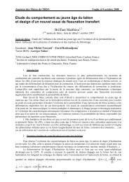
Chapter <strong>2.</strong> Dosimetric Principles, Quantities <strong>and</strong> UnitsFIG. <strong>2.</strong><strong>2.</strong> Unrestricted S/ρ <strong>and</strong> restricted ((L/ρ) ∆ with ∆ = 10 keV <strong>and</strong> 100 keV) total massstopping powers for carbon, based on data published in the ICRU Report 37. Vertical linesindicate the points at which restricted <strong>and</strong> unrestricted mass stopping powers begin todiverge as the kinetic energy increases.• As the threshold for maximum energy transfer in the restricted stopping powerincreases, the restricted mass stopping power tends to the unrestricted massstopping power for ∆ → KE/<strong>2.</strong> Note also that since energy transfers to secondaryelectrons are limited to KE/2, unrestricted <strong>and</strong> restricted electron mass stoppingpowers are identical for kinetic energies lower than or equal to 2∆. This isindicated in Fig. <strong>2.</strong><strong>2.</strong> with vertical lines at 20 keV <strong>and</strong> 200 keV.• The total mass stopping power is the sum of the collision mass stopping power<strong>and</strong> the radiative mass stopping power. Figure <strong>2.</strong><strong>2.</strong> shows the total unrestricted<strong>and</strong> restricted (∆ = 10 keV, 100 keV) electron mass stopping powers for carbonbased on the data in the ICRU Report 37.<strong>2.</strong>7. RELATIONSHIPS BETWEEN VARIOUS DOSIMETRIC QUANTITIES<strong>2.</strong>7.1. Energy fluence <strong>and</strong> kerma (photons)The energy transferred to electrons by photons can be expended in two distinct ways:(1) through collision interactions (soft collisions, hard collisions),(2) through radiative interactions (bremsstrahlung, electron-positron annihilation).Therefore, the total kerma is usually divided into two components: the collision kerma K col<strong>and</strong> the radiative kerma K rad .44
Chapter <strong>2.</strong> Dosimetric Principles, Quantities <strong>and</strong> UnitsIn Eq. (<strong>2.</strong>18)Emax∫Ψ= Ψ0E( EdE )st<strong>and</strong>s for the total (integrated) energy fluence, <strong>and</strong>max⎛µ ⎞en= 1 E µ⎜ en ⎟ ΨE( E) ( E)ρ Ψ∫⎝ ⎠ρd E is a shorth<strong>and</strong> notation for the mass energy0absorption coefficient for the medium averaged over the energy fluence spectrum.• For mono-energetic photons the total kerma K at a point in a medium is related tothe energy fluence Ψ in the medium by the following equation:K⎛µρtr⎞=Ψ ⎜⎝ ⎟ , (<strong>2.</strong>19)⎠where (µ tr/ ρ) is the mass-energy transfer coefficient of the medium for the givenmonoenergetic photon beam. For poly-energetic beams, similarly as above,spectrum-averaged mass-energy transfer coefficients can be used in conjunctionwith total energy fluence to obtain the total kerma.• Note that, using Eq. <strong>2.</strong>17, one can obtain the frequently used relation betweencollision kerma in two different materials, material 1 <strong>and</strong> material 2, as follows:KK⎛µ⎞enΨ2 ⎜ 2col,2 ρ ⎟2 2⎛µen⎞=⎝ ⎠≡( Ψ)1 ⎜ ⎟col,1⎛µen⎞ ρ1Ψ⎝ ⎠1 ⎜ρ ⎟⎝ ⎠1. (<strong>2.</strong>20)This equation is often used in circumstances where the fluence ratio( Ψ) 2 1can beassumed unity through a proper scaling of dimensions (the scaling theorem), or forvery similar materials.<strong>2.</strong>7.<strong>2.</strong> Fluence <strong>and</strong> dose (electrons)• Under the conditions that (1) radiative photons escape the volume of interest <strong>and</strong>(2) secondary electrons are absorbed on the spot (or there is charged particleequilibrium of secondary electrons), the absorbed dose to medium D med is relatedto the electron fluence φ medin the medium as follows:Dmedφ⎛S⎞col=med ⎜ ⎟⎝ ρ ⎠med, (<strong>2.</strong>21)where ( S / ρ is the unrestricted mass collision stopping power of the mediumcolat the energy of the electron.)med• Because of electron slowing down, even for a mono-energetic starting electron,there is always a primary electron fluence spectrum in the medium which isdifferential in energy <strong>and</strong> can be denoted by φ ( E).med,E46
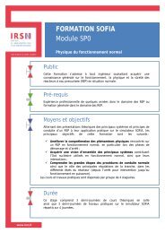
Chapter <strong>2.</strong> Dosimetric Principles, Quantities <strong>and</strong> UnitsAs a high energy photon beam penetrates the medium, collision kerma is maximalat the surface of the irradiated material because photon fluence is greatest at thesurface. Initially, the charged particle fluence, <strong>and</strong> hence the absorbed dose,increases as a function of depth until the depth of dose maximum z m axis attained.• If there were no photon attenuation or scattering in the medium, but yetproduction of electrons, a hypothetical situation, as illustrated in Fig. <strong>2.</strong>3(a),would occur: the build-up region (with β < 1) is followed by a region of completeCPE where D = K col, i.e., β = 1.• In the more realistic situation, however, due to photon attenuation <strong>and</strong> scatteringin the medium, a region of TCPE occurs (Fig. <strong>2.</strong>3(b)) where there exists anessentially constant relation between collision kerma <strong>and</strong> absorbed dose. Thisrelation is practically constant since, in high-energy photon beams, the averageenergy of the generated electrons <strong>and</strong> hence their range does not changeappreciably with depth in the medium.FIG. <strong>2.</strong>3. Collision kerma <strong>and</strong> absorbed dose as a function of depth in a medium, irradiatedby a high-energy photon beam.48
Review of Radiation Oncology Physics: A H<strong>and</strong>book for Teachers <strong>and</strong> Students• In the special case where true charged particle equilibrium exists (at the depth ofmaximum dose in the medium), the relation between absorbed dose D <strong>and</strong> totalkerma K is given by:D= Kcol = K(1 − g), (<strong>2.</strong>25)where g is the bremsstrahlung fraction, depending on the electron kinetic energy;the higher the energy, the larger is g . The bremsstrahlung fraction also dependson the material considered, with higher values of g for higher Z materials. Forelectrons produced by cobalt-60 gamma rays in air the bremsstrahlung fractionequals to 0.003<strong>2.</strong>• The build-up of absorbed dose is responsible for the skin sparing effect in the caseof high-energy photon beams. However, in practice the surface dose is small butdoes not equal zero because of the electron contamination in the beam due tophoton interactions in the media upstream from the phantom or due to chargedparticles generated in the accelerator head <strong>and</strong> beam modifying devices.<strong>2.</strong>7.4. Collision kerma <strong>and</strong> exposure• Exposure X is the quotient of dQ by dm, where dQ is the absolute value of thetotal charge of the ions of one sign produced in air when all the electrons <strong>and</strong>positrons liberated or created by photons in mass dm of air are completelystopped in air:XdQ= . (<strong>2.</strong>26)dmThe unit of exposure is coulomb per kilogram (C/kg). The special unit used forexposure is the roentgen R, where 1 R = <strong>2.</strong>58 x 10 -4 C/kg. In the SI system of <strong>units</strong>,roentgen is no longer used <strong>and</strong> the unit of exposure is simply <strong>2.</strong>58×10 -4 C/kg ofair.• The average energy expended in air per ion pair formed W air is the quotient of Eby N, where N is the mean number of ion pairs formed when the initial kineticenergy E of a charged particle is completely dissipated in air:WairE= . (<strong>2.</strong>27)NThe current best estimate for the average value of W air is 33.97 eV/ion pair or33.97 × 1.602 × 10 19 J/ion pair:Weair−19( ion pair) × × ( )−191.602×10 ( C / ion pair)33.97 eV / 1.602 10 J / eV= =33.97 J/C .(<strong>2.</strong>28)49
Chapter <strong>2.</strong> Dosimetric Principles, Quantities <strong>and</strong> Units• Multiplying the collision kerma by ( e/W )air, the number of coulombs of chargecreated per joule of energy deposited, gives the charge created per unit mass of airor exposure:X( K )⎛e⎞=col air ⎜ ⎟Wair⎝⎠. (<strong>2.</strong>29)• The relationship between total kerma <strong>and</strong> exposure is obtained by combiningEq. <strong>2.</strong>25 <strong>and</strong> Eq. <strong>2.</strong>29 to get:Kair⎛W⎝ e⎞air= X ⎜ ⎟⎠11−g. (<strong>2.</strong>30)<strong>2.</strong>8 CAVITY THEORYIn order to measure the absorbed dose in a medium, it is necessary to introduce a radiationsensitive device (dosimeter) into the medium. Generally, the sensitive medium of thedosimeter will not be of the same material as the medium in which it is embedded. Cavitytheory relates the absorbed dose in the dosimeter sensitive medium (cavity) to the absorbeddose in the surrounding medium containing the cavity. Cavity sizes are referred to as small,intermediate or large in comparison with the ranges of secondary charged particles producedby photons in the cavity medium. If, for example, the range of charged particles (electrons) ismuch larger than the cavity dimensions, the cavity is regarded as small. Various cavitytheories for photon beams have been developed depending on the size of the cavity, such asthe Bragg-Gray <strong>and</strong> Spencer-Attix theories for small cavities <strong>and</strong> the Burlin theory for cavitiesof intermediate sizes.<strong>2.</strong>8.1. The Bragg-Gray cavity theoryThe Bragg-Gray (B-G) cavity theory was the first cavity theory developed to provide arelationship between absorbed dose in a dosimeter <strong>and</strong> the absorbed dose in the mediumcontaining the dosimeter.• The conditions for application of the Bragg-Gray cavity theory are:(1) the cavity must be small when compared with the range of charged particlesincident on it so that its presence does not perturb the fluence of chargedparticles in the medium;(2) the absorbed dose in the cavity is deposited solely by charged particlescrossing it, i.e., photon interactions in the cavity are assumed negligible <strong>and</strong>thus ignored.The result of condition (1) is that the electron fluences in Eq. (<strong>2.</strong>22) are the same<strong>and</strong> equal to the equilibrium fluence established in the surrounding medium. Thiscondition can only be valid in regions of CPE or TCPE. In addition, the presenceof a cavity always causes some degree of fluence perturbation that requires theintroduction of a fluence perturbation correction factor.50
Review of Radiation Oncology Physics: A H<strong>and</strong>book for Teachers <strong>and</strong> StudentsCondition (2) implies that all electrons depositing the dose inside the cavity areproduced outside the cavity <strong>and</strong> completely cross the cavity. Therefore, nosecondary electrons are produced inside the cavity <strong>and</strong> no electrons stop withinthe cavity.• Under these two conditions, according to the Bragg-Gray cavity theory, the doseto the medium D med is related to the dose in the cavity D cav as follows:Dmed⎛S⎞= Dcav⎜ ⎟⎝ρ⎠med,cav, (<strong>2.</strong>31)where (S / ρ) med,cavis the ratio of the average unrestricted mass collision stoppingpowers of the medium <strong>and</strong> cavity. The use of unrestricted stopping powers rulesout the production of secondary charged particles (or delta electrons) in the cavity<strong>and</strong> the medium.• Although the cavity size is not explicitly taken into account in the Bragg-Graycavity theory, the fulfillment of the two Bragg-Gray conditions will depend on thecavity size which is based on the range of the electrons in the cavity medium, thecavity medium, <strong>and</strong> electron energy. A cavity that qualifies as a Bragg-Graycavity for high energy photon beams, for example, may not behave as a Bragg-Gray cavity in a medium-energy or low-energy x-ray beam.<strong>2.</strong>8.<strong>2.</strong> The Spencer-Attix cavity theory• The Bragg-Gray cavity theory does not take into account the creation ofsecondary (delta) electrons generated as a result of the slowing down of theprimary electrons in the sensitive volume of the dosimeter. The Spencer-Attix (S-A) cavity theory is a more general formulation that accounts for the creation ofthese electrons which have sufficient energy to produce further ionisation on theirown account. Some of these electrons released in the gas cavity would havesufficient energy to escape from the cavity carrying some of their energy withthem. This reduces the energy absorbed in the cavity <strong>and</strong> requires modification tothe stopping power of the gas. The Spencer-Attix cavity theory operates under thetwo Bragg-Gray conditions, however, these conditions now even apply to thesecondary particle fluence in addition to the primary charged particle fluence.• The secondary electron fluence in the Spencer-Attix theory is divided into twocomponents based on a user-defined energy threshold ∆. Secondary electronswith kinetic energies KE less than ∆ are considered slow electrons that deposittheir energy locally; secondary electrons with energies larger than or equal to ∆are considered “fast” (slowing down) electrons <strong>and</strong> are part of the electronspectrum. Consequently, this spectrum has a low energy threshold of ∆ <strong>and</strong> ahigh-energy threshold of KEo where KE o represents the initial electron kineticenergy. Since the lowest energy in the spectrum is ∆, the maximum energy loss ofa fast electron with kinetic energy KE larger than or equal to 2∆ cannot be largerthan ∆ <strong>and</strong> the maximum energy loss of a fast electron with kinetic energy lessthan 2∆ cannot be larger than KE/2 (where ∆ ≤ KE < 2∆).51
Chapter <strong>2.</strong> Dosimetric Principles, Quantities <strong>and</strong> Units• Spencer-Attix cavity theory can be used to calculate the dose in the medium as:(<strong>2.</strong>37)⎛µ en⎞ ⎛µen⎞ Q ⎛Wgas⎞ ⎛µen⎞Dmed = Dwall ⎜ ⎟ = Dgas swall,gas ⎜ ⎟ = ⎜ ⎟ swall,gas⎜ ⎟ ,⎝ ρ ⎠ ⎝ ρ ⎠ m ⎝ e ⎠ ⎝ ρ ⎠med,wall med,wall med,wallwhere s wall,gasis the ratio of restricted mass collision stopping powers for cavity wall<strong>and</strong> gas with threshold ∆. In practice, there are additional correction factorsassociated with Eq. (<strong>2.</strong>36) to satisfy the assumptions (1) <strong>and</strong> (2) made above.A similar equation to Eq. (<strong>2.</strong>36) is used for air-kerma in air calibrations, however,here the quantity of interest is not the dose to the medium rather it is the air-kermain-air. In this case, a substantial wall correction is introduced to ensure thepresence of complete CPE in the wall to satisfy assumption (1) above.• In the case of a thin-walled ionisation chamber in a high energy photon or electronbeam, the wall, the cavity <strong>and</strong> the central electrode are treated as a perturbation tothe medium fluence <strong>and</strong> the equation now involves the ratio of restricted collisionstopping powers medium to gas as:Q ⎛W⎞D = ⎜ ⎟s p pm ⎝ e ⎠gasmed med,gas fl dis wall celwherep flp p , (<strong>2.</strong>38)is the electron fluence perturbation correction factor;p disis the correction factor for displacement of the effective measurement pointp wallis the wall correction factor, <strong>and</strong>p celis the correction factor for the central electrode.Values for these multiplicative correction factors are summarized for photon <strong>and</strong>electron beams in typical dosimetry protocols (see Section 9.7 for details).<strong>2.</strong>8.4. Large cavities in photon beamsA large cavity is a cavity with dimensions such that the dose contribution made by electronsinside the cavity originating from photon interactions outside the cavity can be ignored whencompared with the contribution of electrons created by photon interactions within the cavity.For a large cavity the ratio of dose cavity to medium is calculated as the ratio of the collisionkerma in the cavity to the medium <strong>and</strong> is therefore equal to the ratio of the average massenergyabsorption coefficients, cavity to medium:DDgasmed⎛µ⎞en= ⎜ ⎟⎝ ρ ⎠gas,med, (<strong>2.</strong>39)where the mass-energy absorption coefficients have been averaged over the photon fluencespectra in the cavity gas (numerator) <strong>and</strong> in the medium (denominator).54
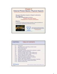
Chapter <strong>2.</strong> Dosimetric Principles, Quantities <strong>and</strong> Unitswhere β is an effective electron fluence attenuation coefficient that quantifies thereduction in particle fluence from its initial medium fluence value through a cavityof average length L. For convex cavities <strong>and</strong> isotropic electron fluence distributions,L can be calculated as 4V/S where V is the cavity volume <strong>and</strong> S its surfaceearea. Burlin described the build-up of the electron fluence Φgasinside the cavityusing a similar, complementary equation:1Le −βl∫ Φgas(1 −e) dl0− d = =Le∫ Φgasdl0β L− 1+eβ L−βL. (<strong>2.</strong>42)• Burlin’s theory is consistent with the fundamental constraint of cavity theory that,the weighting factors of both terms add up to unity (i.e., d <strong>and</strong> 1-d). It had relativesuccess in calculating ratios of absorbed dose for some types of intermediatecavities. More generally, however, Monte Carlo calculations show that, whenstudying ratios of directly calculated absorbed doses in the cavity to absorbeddose in the medium as a function of cavity size, the weighting method is toosimplistic <strong>and</strong> additional terms are necessary to calculate dose ratios forintermediate cavity sizes. For these <strong>and</strong> other reasons, the Burlin cavity theory isno longer used in practice.<strong>2.</strong>8.6. Stopping power ratios• Although cavity theory was designed to calculate ratios of absorbed doses, thepractical application of the Spencer-Attix cavity theory has always requiredadditional correction factors. Since the central component of Spencer-Attix cavitytheory results in averaging stopping powers, Spencer-Attix dose ratios are oftenreferred to as “stopping power ratios”.• Stopping power ratios not only play a role in the absolute measurement ofabsorbed dose, they are also relevant in performing accurate relativemeasurements of absorbed dose in regimes where the energy of the secondaryelectrons changes significantly from one point in a phantom to another. Animportant example of this is apparent from Fig. <strong>2.</strong>4 which shows restrictedstopping power ratios (∆ = 10 keV) of water to air for electron beams as afunction of depth in water. Note that these curves are for mono-energeticelectrons; protocols or codes of practice for electron dosimetry provide fits ofstopping power ratios for realistic accelerator beams. However, Fig. <strong>2.</strong>4 showsclearly that the accurate measurement of electron beam depth dose curves requiresdepth-dependent correction factors.• In photon beams, except at or near the surface, average restricted stopping powerratios of water to air do not vary significantly as a function of depth. Stoppingpower ratios (with ∆ = 10 keV) under full build-up conditions are given inTable <strong>2.</strong>1.• More detailed information on stopping power ratios is given in Section 9.5.56
Review of Radiation Oncology Physics: A H<strong>and</strong>book for Teachers <strong>and</strong> StudentsFIG. <strong>2.</strong>4. Restricted collision stopping power ratio of water to air (∆ = 10 keV) as afunction of depth for different mono-energetic electron energies.TABLE <strong>2.</strong>I. AVERAGE RESTRICTED STOPPING POWER RATIO OF WATER TO AIRFOR DIFFERENT PHOTON SPECTRA IN THE RANGE FROM COBALT-60 GAMMARAYS TO 35 MV X RAYS.Photon Spectra swater,air60 Co 1.1344 MV 1.1316 MV 1.1278 MV 1.12110 MV 1.11715 MV 1.10620 MV 1.09625 MV 1.09335 MV 1.08457
Chapter <strong>2.</strong> Dosimetric Principles, Quantities <strong>and</strong> UnitsBIBLIOGRAPHYATTIX, F.H., “Introduction to radiological physics <strong>and</strong> radiation dosimetry”., John Wiley,New York, New York, U.S.A. (1986).GREENING, J.R., “Fundamentals of radiation dosimetry”, Adam Hilger, Bristol, UnitedKingdom (1981).INTERNATIONAL COMMISSION ON RADIATION UNITS AND MEASUREMENTS,(ICRU), “Stopping powers for electrons <strong>and</strong> positrons”, ICRU Report 37, ICRU, Bethesda,Maryl<strong>and</strong>, U.S.A. (1984).INTERNATIONAL COMMISSION ON RADIATION UNITS AND MEASUREMENTS,(ICRU), “Fundamental <strong>quantities</strong> <strong>and</strong> <strong>units</strong> for ionizing radiation”, ICRU Report 60, ICRU,Bethesda, Maryl<strong>and</strong>, U.S.A. (1998).JOHNS, H.E., CUNNINGHAM, J.R., “The physics of radiology”, Thomas, Springfield,Illinois, U.S.A. (1985).58