M2 Antenna Systems, Inc. Model No: 2M12 - N4brf.org
M2 Antenna Systems, Inc. Model No: 2M12 - N4brf.org
M2 Antenna Systems, Inc. Model No: 2M12 - N4brf.org
Create successful ePaper yourself
Turn your PDF publications into a flip-book with our unique Google optimized e-Paper software.
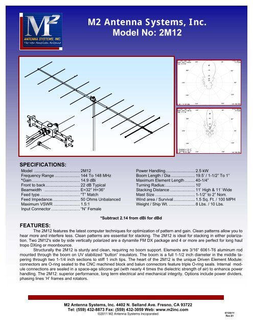
<strong>2M12</strong> ASSEMBLY MANUAL9. The boom to mast plate is normally mounted at the balance point. Since the feedline representssignificant weight it is best to have it attached and fastened along the boom with cable ties beforefinal mounting of the plate. Use two 1-1/2" U-bolts and the stainless nuts and lock washersprovided. DO NOT OVER TIGHTEN. 2” U-bolts are provided for mounting the antenna to yourmast.10. INSTALLATION AND STACKING INFORMATIONA. To protect your investment in this high performance antenna, always use high quality coax andconnectors. Old, corroded, or poor quality materials are common sources of serious performancelosses.B. If possible, test the antenna, connectors and feedline BEFORE installing to your mast or tower.At 6 feet or more the antenna will exhibit VSWR similar to higher mounting heights. Set antennaon a ladder or temporary mast. Check for continuity and match across the band. It should be 1.5:1or better from 144 to 148 MHz.C. STACKING REMINDERS:1. All driven element blocks MUST be oriented to the same side of boom.2. All boom-to-mast plates MUST be mounted at the same point on the boom.3. Feed / phasing lines MUST be of equal electrical length or multiples of 1 wavelength in order tomaintain equal phasing in the array. Improper phasing can severely deteriorate performance.FOR HORIZONTAL POLARIZATION, the <strong>2M12</strong> may be mounted to a metallic vertical mast or ahorizontal NON-METALLIC crossboom (no conductive material in element plane). If mounted to ahorizontal crossboom, route the feedline forward to the boom-to-mast plate, loop down, and bringback to crossboom at least 6” beyond element tips. Two <strong>2M12</strong> antennas are ideal for stacking, oneabove the other in horizontal polarity. H plane optimum stacking distance is 11’. 10FOR VERTICAL POLARIZATION, the <strong>2M12</strong> may be mounted to a NON METALLIC VERTICALMAST (no conductive material in element plane) or a horizontal metallic crossboom. If mounted toa vertical mast, route the feed line forward to the boom-to-mast plate, loop out at a right angles tothe boom, and bring down to the mast at least 6 inches BELOW THE ELEMENT TIPS. Twovertically polarized <strong>2M12</strong> antennas are typically stacked side by side on a horizontal crossboom.Stacking distance is 11’.If you are unsure about stacking multiple antennas, please call M 2RIGHTand let us help you DO ITTHIS COMPLETES THE ANTENNA ASSEMBLY.CAREFULLY MANUFACTURED BY:<strong>M2</strong> <strong>Antenna</strong> <strong>Systems</strong>, <strong>Inc</strong>.4402 N. Selland Ave.FRESNO, CA 93722(559) 432-8873 FAX (559) 432-3059www.m2inc.com
<strong>2M12</strong> DIMENSION SHEETELEMENTSPACING.5016.93724.37538.1881X3017.75"27.0ELEMENTLENGTH40.039.0 & 40.2537.7536.93755.87574.501-1/4 X 60 SOE35.93735.7584.098.62535.5122.875146.188175.01-1/4 X 60" SOE 1-1/2 X 60 SBE144.034.7534.534.75205.125201.034.6251 X 36233.25234.035.0
<strong>2M12</strong> ASSEMBLY DETAILS
<strong>2M12</strong> PARTS & HARDWAREDESCRIPTION...................................................QTYBOOM SECTION, 1-1/2 X .058 X 60” SBE ........1BOOM SECTION, 1-1/4 X .058 X 60” SOE ........2BOOM SECTION, 1 X .058 X 36” STR...............1BOOM SECTION, 1 X .058 X 30” STR...............1ELEMENTS, 3/16 ROD x Dimension Sheet .......12DRIVEN ELEMENT BLOCK ASSEMBLY...........1ASSEMBLY MANUAL ........................................1BALUN, RG-6 1/2 WAVE ...................................1BOOM-TO-MAST PLATE, .188 X 6 X 4” ............1U-BOLT AND CRADLE, 2’..................................2U-BOLT AND CRADLE, 1-1/2”...........................2IN HARDWARE BAG:SHORTING BAR ................................................2BUTTON INSULATORS.....................................24SHAFT RETAINER, SS......................................24NUT, 5/16-18 SS ................................................8LOCKWASHER, 5/16 SS ...................................8SETSCREW, 8-32 X 1/4, SS..............................4SCREW, 8-32 X 1-1/4 SS...................................1SCREW, 8-32 X 1-1/2 SS...................................4SCREW, 8-32 X 1-3/4 SS...................................4LOCKNUT, 8-32 SS ...........................................8CABLE TIE, NYLON ..........................................2SEAL NUTS, 3/8-32 ...........................................2ALLEN HEAD WRENCH, 5/64” ..........................1PUSH TUBE, 3/8 X 3” ........................................1<strong>M2</strong> <strong>Antenna</strong> <strong>Systems</strong>, <strong>Inc</strong>.4402 N. Selland Ave.FRESNO, CA 93722(559) 432-8873 FAX (559) 432-3059www.m2inc.com


