BigIR-Mark-IV-Manual.. - SteppIR
BigIR-Mark-IV-Manual.. - SteppIR
BigIR-Mark-IV-Manual.. - SteppIR

You also want an ePaper? Increase the reach of your titles
YUMPU automatically turns print PDFs into web optimized ePapers that Google loves.
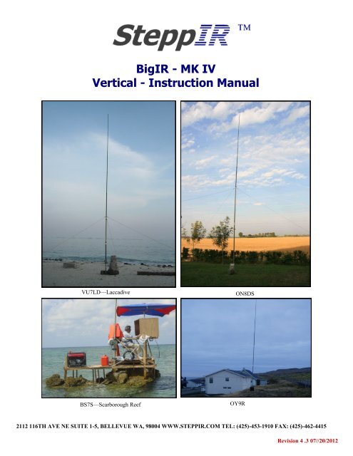
<strong>BigIR</strong> - MK <strong>IV</strong><br />
Vertical - Instruction <strong>Manual</strong><br />
VU7LD—Laccadive<br />
ON8DS<br />
BS7S—Scarborough Reef<br />
OY9R<br />
2112 116TH AVE NE SUITE 1-5, BELLEVUE WA, 98004 WWW.STEPPIR.COM TEL: (425)-453-1910 FAX: (425)-462-4415<br />
Revision 4 .3 07//20/2012
Table of Contents<br />
Topic<br />
Page<br />
Table of contents 2<br />
<strong>SteppIR</strong> - Why Compromise ? 3<br />
<strong>SteppIR</strong> Design 4<br />
<strong>BigIR</strong> vertical components 5<br />
Installing the <strong>BigIR</strong> extension tube / telescoping poles 5-9<br />
Installation of rain cap 6<br />
Installing the element support extension tubes 7<br />
Polyolefin heat shrink procedure 8<br />
Securing the telescoping pole to the element support tube (EST) extension 9<br />
Element housing unit (EHU) wiring instructions 10<br />
Reinforcing assembly installation instructions 11—14<br />
Installing the optional 80m Coil 15<br />
Ground mounting of the <strong>BigIR</strong> vertical 16<br />
Recommended radials for ground and above ground installations 17<br />
Installing the optional 1:1 balun 18<br />
More about choosing radial systems for ground / above-ground installations 19-23<br />
Using a vertical in or on salt water 23<br />
DB25 control cable splice assembly instructions 24<br />
Control cable wiring schematic 25<br />
<strong>SteppIR</strong> Warranty 26<br />
2112 116TH AVE NE SUITE 1-5, BELLEVUE WA, 98004 WWW.STEPPIR.COM TEL: (425)-453-1910 FAX: (425)-462-4415<br />
2
<strong>SteppIR</strong> - Why Compromise?<br />
The <strong>SteppIR</strong> antenna was originally conceived to solve the problem of covering the six ham<br />
bands (20m, 17m, 15m, 12m, 10m and 6m) on one tower without the performance sacrifices<br />
caused by interaction between all of the required antennas.<br />
Yagis are available that cover 20 meters through 10 meters by using interlaced elements or<br />
traps, but do so at the expense of significant performance reduction in gain and front to back<br />
ratios. With the addition of the WARC bands on 17m and 12m, the use of interlaced elements<br />
and traps has clearly been an exercise in diminishing returns.<br />
Obviously, an antenna that is precisely adjustable in length while in the air would solve the frequency<br />
problem, and in addition would have vastly improved performance over existing fixed<br />
length yagis. The ability to tune the antenna to a specific frequency, without regard for bandwidth,<br />
results in excellent gain and front to back at every frequency.<br />
The <strong>SteppIR</strong> design was made possible by the convergence of determination and high tech<br />
materials. The availability of new lightweight glass fiber composites, Teflon blended thermoplastics,<br />
high conductivity copper-beryllium and extremely reliable stepper motors has allowed<br />
the <strong>SteppIR</strong> to be a commercially feasible product.<br />
The current and future <strong>SteppIR</strong> products should produce the most potent single tower antenna<br />
systems ever seen in Amateur Radio! We thank you for using our <strong>SteppIR</strong> antenna for your<br />
ham radio endeavors.<br />
Warm Regards,<br />
Mike Mertel<br />
Michael (Mike) Mertel - K7IR<br />
President<br />
2112 116TH AVE NE SUITE 1-5, BELLEVUE WA, 98004 WWW.STEPPIR.COM TEL: (425)-453-1910 FAX: (425)-462-4415<br />
3
<strong>SteppIR</strong> Design<br />
Currently, most multi-band antennas use traps, log cells or interlaced elements as a means to cover several frequency<br />
bands. All of these methods have one thing in common–they significantly compromise performance.<br />
The <strong>SteppIR</strong> antenna system is our answer to the problem. Resonant antennas must be made a specific<br />
length to operate optimally on a given frequency.<br />
So, instead of trying to “trick” the antenna into thinking it is a different length, or simply adding more elements<br />
that may destructively interact, why not just change the antenna length? Optimal performance is then possible<br />
on all frequencies with a lightweight, compact antenna. Also, since the <strong>SteppIR</strong> can control the element<br />
lengths, a long boom is not needed to achieve near optimum gain and front to back ratios on 20 - 10 meters.<br />
Each antenna element consists of two spools of flat copper-beryllium tape conductor (.54” Wide x .008” Thick)<br />
mounted in the element housing unit. The copper-beryllium tape is perforated to allow a stepper motor to drive<br />
them simultaneously with sprockets. Stepper motors are well known for their ability to index very accurately,<br />
thus giving very precise control of each element length. In addition, the motors are brushless and provide extremely<br />
long service life.<br />
The copper-beryllium tape is driven out into a hollow fiberglass elements support tube (see below), forming an<br />
element of any desired length up to the limit of each specific antenna model (a vertical uses only one side). The<br />
fiberglass elements support tubes (poles) are telescoping, lightweight and very durable. When fully collapsed,<br />
each one measures approximately 48” in length. Depending on the model, there may be additional extensions<br />
added to increase the overall element length.<br />
The ability to completely retract the copper-beryllium antenna elements, coupled with the collapsible fiberglass<br />
poles makes the entire system easy to disassemble and transport.<br />
The antenna is connected to a microprocessor-based controller (via 22 gauge conductor cable) that offers<br />
numerous functions including dedicated buttons for each ham band, continuous frequency selection<br />
from 40m to 6m (depending on the model). There are also 17 ham and 6 non-ham band memories and<br />
you can select a 180° direction reversal* or bi-directional* mode and it will adjust in just about 3 seconds<br />
(* yagi only).<br />
Element Support Tube<br />
Boom<br />
Copper Beryllium Tape<br />
Stepper Drive Motor<br />
Element Housing Unit<br />
2112 116TH AVE NE SUITE 1-5, BELLEVUE WA, 98004 WWW.STEPPIR.COM TEL: (425)-453-1910 FAX: (425)-462-4415<br />
4
Installing the <strong>BigIR</strong> Extension Tube / Telescoping poles<br />
A<br />
B<br />
C<br />
D<br />
E<br />
F<br />
Glue Kit<br />
G<br />
Rubber<br />
Boots<br />
H<br />
I<br />
<strong>Manual</strong>s<br />
A: Lower EST Extension #70-2019-01 B: Lower diverter extension #70-2022-01 C: Upper EST extension #70-2020-01<br />
D: Upper diverter extension #70-2021-01 E: Telescoping fiberglass pole #09200 F: 24” Aluminum mounting post #09506<br />
G: Element housing unit (EHU) #09407 H: Guy hardware Kit #09602 I: Rain cap #10-1105-01<br />
<br />
<br />
<br />
Lay the element housing unit (EHU), Figure 1 - G, and element support tube extensions (EST)<br />
Figure 1 - A,C flat on their sides. There will be a 3/4” diameter piece of plastic pipe protruding<br />
out the end of the EST with a coupler attached to it (Figure 5).<br />
Firmly glue in (using the PVC primer/glue supplied) the 89” section of 3/4” diameter plastic pipe<br />
(Figure 1 - D), that also has a coupler attached to one end.<br />
Next glue in the second section of 3/4” diameter plastic pipe (Figure 1 - B) with the inside<br />
chamfered ends.<br />
NOTE: If you need to take the antenna apart in the future you can cut the 3/4” diameter plastic pipe<br />
(after homing the copper) a minimum of 1 in. above the coupler and when you are ready to<br />
reinstall the plastic pipe glue in a new coupler.<br />
<br />
Now install the two section of the EST extension tube (Figure 1 - A, C). The first section goes<br />
firmly onto the EHT tube and the second EST goes on to the end of the first section. (Figure 7<br />
and Figure 9 on next page)<br />
Warning: Be certain that the metal coupler on the extension ESTs firmly bottom out.<br />
Figure 3<br />
Figure 5<br />
2112 116TH AVE NE SUITE 1-5, BELLEVUE WA, 98004 WWW.STEPPIR.COM TEL: (425)-453-1910 FAX: (425)-462-4415<br />
5
Fig 7: EST extensions<br />
with plastic diverter tube showing<br />
Fig 9: EST Extensions after sliding<br />
the top section over the bottom section<br />
Installation of the Rain Cap<br />
On the tip of the pole you will install a black cap (Figure 19) with a piece of tubing passing<br />
through it. The purpose of this vent cap is to keep the rain out, yet still allow air flow through<br />
the foam plug into the telescoping pole.<br />
Warning: Press the cap on approximately 1-1/8” (Figure 20). Do NOT press the cap down so<br />
hard as to crimp (damage) the cross tube preventing the pole from properly venting.<br />
Rain Cap & Vent<br />
Figure 19<br />
Figure 20<br />
1.125<br />
2112 116TH AVE NE SUITE 1-5, BELLEVUE WA, 98004 WWW.STEPPIR.COM TEL: (425)-453-1910 FAX: (425)-462-4415<br />
6
<strong>BigIR</strong> EST Extension Tube Instructions<br />
FIGURE A<br />
2112 116TH AVE NE SUITE 1-5, BELLEVUE WA, 98004 WWW.STEPPIR.COM TEL: (425)-453-1910 FAX: (425)-462-4415<br />
7
Polyolefin Heat Shrink Installation<br />
On all elements we now include double wall polyolefin heat shrink, part number #03630. Each telescoping<br />
pole uses 3 pieces of the 1.5” x 3” long heat shrink, which forms an adhesive bond that is heat activated.<br />
Once finished, the seal is secure and waterproof. This new process replaces the use of electrical tape and<br />
silicone wrap. Note: The EST extension tubes will use the 2.05” x 4” heat shrink, as shown on page 7.<br />
This product requires a heat gun for activation of the adhesive. When positioning the heat shrink, place it so<br />
that the joint of the telescoping pole is centered in the middle of the heat shrink. The pictures below exhibit<br />
how this is done. Apply heat around the entire area of heat shrink.<br />
Note: There are 4 blue colored lines imprinted on the tubing. The joint is considered done being heated and<br />
waterproof when the lines change color to a yellowish green. Each line needs to change in color to ensure<br />
even adhesion temperatures. With this change, there is no longer any need to tape the joints on the loop<br />
elements.<br />
2112 116TH AVE NE SUITE 1-5, BELLEVUE WA, 98004 WWW.STEPPIR.COM TEL: (425)-453-1910 FAX: (425)-462-4415<br />
8
Attaching the Telescoping Pole to the EST Tube Extensions<br />
NOTE: The pole was tested at the factory prior to shipping, however in the event the pole won’t fit<br />
sanding it is okay.<br />
Locate the rubber boot.<br />
<br />
<br />
<br />
<br />
<br />
Place the narrow end of a rubber boot onto the butt end of the EST (pole). Slide it about 6” out<br />
onto the EST (Figure 21-A).<br />
Insert the butt end of that EST into the extension tube until the raised black ring is approximately<br />
1/2 in. above the extension tube (Figure 21-B).<br />
Push the rubber boot firmly onto the extension tube until the screw clamp is past the aluminum ring<br />
and will clamp down onto the fiberglass (Figure 21-C).<br />
The upper screw clamp should be past the raised black ring to get the proper seal on the telescoping<br />
pole (Figure 21-C).<br />
Firmly tighten both stainless steel screw clamps. Then test the connection by pulling and twisting<br />
it. There should be no slippage at the joints.<br />
NOTE: You should re-tighten each clamp a second time (at least 30 minutes<br />
after the first time you tightened them) before raising the antenna<br />
to the tower, to be sure that there has been no cold flowing<br />
of the PVC material on the rubber boot.<br />
Figure 21<br />
A<br />
B<br />
C<br />
2112 116TH AVE NE SUITE 1-5, BELLEVUE WA, 98004 WWW.STEPPIR.COM TEL: (425)-453-1910 FAX: (425)-462-4415<br />
9
Element Housing Unit (EHU) Wiring Instructions<br />
Refer to page 24-25 for<br />
2112 116TH AVE NE SUITE 1-5, BELLEVUE WA, 98004 WWW.STEPPIR.COM TEL: (425)-453-1910 FAX: (425)-462-4415<br />
10
<strong>BigIR</strong> <strong>Mark</strong> <strong>IV</strong> Reinforcing Plate Installation<br />
NOTE: The new <strong>BigIR</strong> <strong>Mark</strong> <strong>IV</strong> vertical model was introduced in November 2011. All <strong>BigIR</strong> vertical antennas<br />
are now made to the specifications of the <strong>Mark</strong> <strong>IV</strong>. This next section describes how to install the reinforcing<br />
kit for your <strong>BigIR</strong> vertical. The pictures below show the completed reinforcing kit installation.<br />
<strong>BigIR</strong> Wind Reinforcing Kit<br />
without 80m coil<br />
<strong>BigIR</strong> Wind Reinforcing Kit<br />
with 80m coil<br />
2112 116TH AVE NE SUITE 1-5, BELLEVUE WA, 98004 WWW.STEPPIR.COM TEL: (425)-453-1910 FAX: (425)-462-4415<br />
11
<strong>BigIR</strong> EHU Wind Reinforcing Kit—Hardware list<br />
Hardware included for <strong>BigIR</strong> without the 80m coil:<br />
Qty Part Number Description<br />
1 10-1501-22 EHU Lid<br />
1 10-1021-52 Reinforcing plate<br />
5 60-0017 #10 x 3/4” Pan head bolt<br />
5 60-0071 #10 x 1” Pan head bolt<br />
15 60-0018 #10 Washer<br />
10 60-0019 #10 Nylock nut<br />
2 60-0066 5/16” x 4” Hex head bolt<br />
2 60-0114 5/16” x 3.75” Hex head bolt<br />
4 60-0046 5/16” Nylock nut<br />
10 60-0033 5/16” Washer<br />
4 10-1613-11 5/16” x 1/4” Aluminum spacer<br />
2 10-1601-03 1.75” Aluminum saddle half<br />
2 10-1601-22 2” Aluminum saddle half<br />
1 09-1022-08 8” Coax-seal<br />
1 10-1502-12 EHU Gasket<br />
1 10-1028-01 Anti-seize packet<br />
Additional hardware included for <strong>BigIR</strong> with the 80m coil:<br />
Qty Part Number Description<br />
5 60-0095 #10 x 2” Pan head bolt<br />
4 10-1004-02 0.50” Plastic spacer<br />
2 10-1613-11 1/4” x 5/16” Aluminum spacer<br />
2112 116TH AVE NE SUITE 1-5, BELLEVUE WA, 98004 WWW.STEPPIR.COM TEL: (425)-453-1910 FAX: (425)-462-4415<br />
12
Wind reinforcing kit installation instructions (continued)<br />
Follow the instructions for preparing the wiring for the <strong>BigIR</strong> EHU. This step must be done before placing the<br />
lid on the EHU. Refer to figure 8.14 on page 10 for more detail on wiring the EHU.<br />
The reinforcing plate has a short side and a long side, as shown in figure 8.1. It is critical that the reinforcing<br />
plate be mounted as shown in figure 8.14, or the saddles will not align properly.<br />
Place the EHU and the EHU gasket on top of the lid as shown in figure 8.2. Use the PN 60-0071 #10 x 1”<br />
screws to attach the reinforcing plate to the EHU, gasket and lid. Each screw will have a PN 60-0018 #10 flat<br />
washer underneath the head of the screw and also underneath the Nylock nut as shown in figure 8.4 . Figure<br />
8.1 shows screw placement. For the 5 bolts that connect the reinforcing plate to the EHU you will only use<br />
a washer on the plastic EHU housing. Use the PN 60-0017 #10 x 3/4” screws to attach the rest of the lid to the<br />
EHU.<br />
Note: If you are installing with the 80m coil option, be sure to read the instructions on page 14 before installing<br />
the reinforcing plate as there are different instructions at this juncture.<br />
Figure 8.1<br />
#10 x 3/4” Pan head<br />
screw PN 60-0017<br />
#10 x 1” Pan head<br />
screw PN 60-0071<br />
LONG SIDE OF REINFORCING PLATE<br />
SHORT SIDE OF REINFORCING PLATE<br />
Figure 8.2<br />
Figure 8.4<br />
2112 116TH AVE NE SUITE 1-5, BELLEVUE WA, 98004 WWW.STEPPIR.COM TEL: (425)-453-1910 FAX: (425)-462-4415<br />
13
Wind reinforcing kit installation instructions (continued)<br />
<br />
<br />
<br />
<br />
<br />
<br />
Insert a 2” aluminum saddle half (10-1601-32) underneath the element support tube (EST) protruding from the EHU.<br />
This will be located on the long end of the reinforcing plate. Place underneath the saddle a single aluminum spacer<br />
(10-1613-11) and a single 5/16 washer (60-0033) as shown in figure 8.5. Slide a PN 60-0066 5/16” x 4” hex head<br />
bolt (thread end pointing skyward) through the spacers and the saddle on each side of the EST. Be sure to use antiseize<br />
on all of your stainless steel fasteners or you will have galling issues.<br />
Place the bottom portion of the EST extension tube (70-2019-01) over the side of the EHU that has the white plastic<br />
coupler protruding. This will be on the “long” side of the reinforcing plate. Be certain that the aluminum coupler at<br />
the bottom of the EST extension firmly bottoms out.<br />
Place the second half of the aluminum saddle as shown in figure 8.7. Loosely place the PN 60-0046 Nylock nuts on<br />
the threaded bolts.<br />
Repeat on the short side of the reinforcing plate by inserting a 1.75” aluminum saddle half (10-1601-03) underneath<br />
the element support tube (EST) protruding from the EHU. This will be located on the short end of the reinforcing<br />
plate. Place underneath the saddle a single aluminum spacer (10-1613-11) and a four of the 5/16 washer (60-0033)<br />
as shown in figure 8.6. Slide a PN 60-0114 5/16” x 3.75” hex head bolt (thread end pointing skyward) through the<br />
spacers and the saddle on each side of the EST.<br />
Tighten the saddles. Be sure to use no more than 15 ft lb of torque or the fiberglass EHU pieces could be damaged.<br />
Figure 8.8 shows the tightened saddles. Try to make the saddle halves as even as possible as shown in figure 8.7.<br />
Refer to the picture on page 9 for a look at a completed <strong>BigIR</strong> reinforcing assembly.<br />
Figure 8.5<br />
Figure 8.6<br />
Figure 8.8<br />
Figure 8.7<br />
2112 116TH AVE NE SUITE 1-5, BELLEVUE WA, 98004 WWW.STEPPIR.COM TEL: (425)-453-1910 FAX: (425)-462-4415<br />
14
Wind reinforcing kit installation instructions—80m Coil Option<br />
If the 80m coil will be mounted to the <strong>BigIR</strong>, the standard pan head screws must be replaced with #10 x 2”<br />
screws (60-0095). Refer to figure 8.9 to locate which holes to use the #10 x 2” screws.<br />
There are two spacers on the end of the EHU without the wind reinforcing plate. One is a 0.50” plastic<br />
spacer (10-1004-02), and the other a 0.250” aluminum spacer (10-1613-11) as shown in figure 8.10.<br />
There is a single 0.50” spacer on the end of the EHU that has the wind reinforcing plate attached as shown<br />
in figure 8.11.<br />
It is difficult for the nut to sit flat on the 80m coil cover, so for the four #10 x 2” pan head bolts used for<br />
mounting we have you put the threads upward, with the Nylock nut being attached on the EHU side of the<br />
connection. Even though the #10 x 2” long screw is reversed, be sure that you still place a flat washer on<br />
the EHU side of the screw (between the Nylock nut and the EHU housing) as shown in figure 8.12.<br />
Place the screws through the 80m cover and the reinforcing plate/EHU lid and tighten.<br />
Do not forget to use anti-seize for all fasteners and be sure to NOT over-tighten.<br />
Page 9 shows a picture of a completed <strong>BigIR</strong> with 80m Coil installation.<br />
Follow the rest of the <strong>BigIR</strong> installation guide for connecting the 80m coil to the <strong>BigIR</strong>.<br />
Figure 8.9<br />
Figure 8.10<br />
Mounting holes<br />
for 80m coil<br />
Figure 8.11<br />
Figure 8.12<br />
2112 116TH AVE NE SUITE 1-5, BELLEVUE WA, 98004 WWW.STEPPIR.COM TEL: (425)-453-1910 FAX: (425)-462-4415<br />
15
Mounting the <strong>BigIR</strong> (ground)<br />
The <strong>BigIR</strong> comes with a 1.5” OD aluminum mounting post, 2 feet in length (Figure 1 - D). If<br />
using guy wires, the antenna can be mounted directly into the ground without concrete (the guy<br />
wires will “lock” the antenna in place) but you want to ensure that the mounting pole does not<br />
shift or settle over time, using concrete to secure it in the ground is a good way to eliminate the<br />
potential for this problem. Position the mounting pole (machined end up) so that the bottom of<br />
the element housing is 8 to 10 inches above the ground (Figure 29).<br />
At this point you want to decide on your guy configuration and mount the guy bracket (s) and<br />
attach the guy wires before erecting the antenna (Figure 35, 36 & 37).<br />
No Guy Wires 50 mph<br />
One set of guy wires 70 mph<br />
Two sets of guy wires (optional bracket) 100 mph<br />
One guy wire connects to one side of the guy bracket and two guy wires connect to the other<br />
side of the guy bracket using the two security snaps (Figure 31).<br />
With the mounting post is in place and level and your guy assembly mounted, you are ready to<br />
erect the antenna. Now slide the small end of the flexible coupler (rubber boot) to the mounting<br />
post (Figure 41). This coupler is used to keep the antenna from potentially “twisting” in high<br />
winds. Pick up the antenna at the base (Figure 33) and slide the antenna housing onto the<br />
mounting pole until it firmly bottoms out. Place the larger end of the flexible coupler over the<br />
antenna housing tube (a small amount of bar soap or other lubricant will help the process).<br />
Tighten clamps on the coupler and secure the guy wires.<br />
Now you are ready to connect the radials! We recommend using a lug connector (crimped &<br />
soldered) at the end of your radials, and then tightening the<br />
lug onto the connector (ground) post shown in Figure 39.<br />
If you purchased the optional radial kits (Figure 28), you<br />
will notice there are 4 wires per set (ground radials), all soldered<br />
and crimped to a lug<br />
Figure 28—Ground radials<br />
connector.<br />
EHU<br />
Figure 29<br />
Figure 31<br />
8 to 10 in.<br />
Figure 33<br />
2112 116TH AVE NE SUITE 1-5, BELLEVUE WA, 98004 WWW.STEPPIR.COM TEL: (425)-453-1910 FAX: (425)-462-4415<br />
16
Recommended Radials<br />
Figure 43<br />
Ground Mounting:<br />
<br />
Min. of 12 - radials cut to the lowest frequency<br />
Elevated Mounting:<br />
<br />
Min. of 2 pre band trimmed to .1 x frequency<br />
Figure 35<br />
Single Guy<br />
Configuration<br />
Figure 37<br />
Double Guy<br />
Configuration<br />
Guy @ 11ft<br />
Above Ground<br />
Bracket (Supplied)<br />
Second Guy @ 15ft<br />
Above Ground<br />
Bracket (optional)<br />
First Guy @ 7.5ft<br />
Above Ground<br />
Bracket (Supplied)<br />
Anchor<br />
Anchor<br />
Antenna<br />
Anchor<br />
Warning:<br />
A 11 ft radius and an even spread (120<br />
deg) are the minimum dimensions<br />
required, when positioning the guy<br />
anchors, to achieve the stated wind<br />
ratings<br />
Figure 36<br />
Figure 41<br />
Figure 39<br />
Mounting<br />
Tube<br />
Ground<br />
Flexible<br />
Coupler<br />
8 to 10 in.<br />
2112 116TH AVE NE SUITE 1-5, BELLEVUE WA, 98004 WWW.STEPPIR.COM TEL: (425)-453-1910 FAX: (425)-462-4415<br />
17
Optional (1:1) External Balun<br />
A balun is an electrical circuit used to help resolve the inherent problem of feeding an antenna<br />
with an electrically unbalanced (coax) feed line. It is intended to present an infinite<br />
impedance to any RF current that might otherwise flow on the outer conductor (shield) of the<br />
coax producing radiation from the line. This current, if high enough, can cause heat buildup<br />
and potential damage to the radio as well as a distorted radiation pattern.<br />
Why is it Optional ?:<br />
In the normal configuration, ground mounted with 12 or more radials, the ground will bleed/<br />
drain the unwanted RF signal from the coax shield.<br />
Coax<br />
Ferrite<br />
Toroidal<br />
Core<br />
Radio<br />
When Should You Use A Balun ?:<br />
When elevating the base of a vertical<br />
antenna above the ground<br />
When only a few radials are used<br />
When the coax run is shorter than the radials<br />
When the ground condition is poor<br />
Unusual SWR readings on one band<br />
Antenna<br />
Balun Installation<br />
Figure 23<br />
The balun is shown in figure 25. There is a<br />
mounting flange with 4 holes molded into the<br />
housing. There are numerous options for mounting<br />
the balun—by far the most popular is to mount the balun on an adjacent post or similar<br />
structure, or even on a piece of wood that rests on the ground. Figure 26 shows how to connect<br />
the balun when using the <strong>BigIR</strong> without the 80m coil. Figure 27 shows how to connect<br />
the balun with a <strong>BigIR</strong> and optional 80m coil.<br />
Figure 25<br />
Figure 26<br />
Figure 27<br />
2112 116TH AVE NE SUITE 1-5, BELLEVUE WA, 98004 WWW.STEPPIR.COM TEL: (425)-453-1910 FAX: (425)-462-4415<br />
18
All vertical monopoles need some form of counterpoise in which antenna image currents flow<br />
to work efficiently. This counterpoise usually consists of a system of radial wires placed either<br />
on the ground or elevated above ground.<br />
This is not an in depth publication but simply a general guide on installing and using the <strong>SteppIR</strong><br />
verticals. There is much more information available in various publications if you need it.<br />
The ARRL Antenna Handbook is a good source for additional information.<br />
By following a few simple guidelines, you can obtain excellent performance from vertical antennas<br />
mounted on the ground or elevated above the ground. There are a number of verticals<br />
available that say “no radials required”, but they do have “radials”, in the form of a shortened,<br />
tuned counterpoise system. As you might expect, you pay a price for such a small counterpoise<br />
system - less efficiency.<br />
As you will see in the following pages, you can get fairly high efficiency with a relatively modest<br />
radial system that will far outperform small counterpoise systems. It should be noted that<br />
counterpoise systems are only good for curing near field losses caused by losses from the earth,<br />
which is a poor conductor of RF, even with good soil. There is nothing you can do about far<br />
field losses that reduce the signal strength and low angle radiation, except get to some saltwater.<br />
We briefly discuss salt water locations later on in this article.<br />
Ground Mount or Elevate?<br />
Ground Mounting:<br />
PROS<br />
CONS<br />
<br />
<br />
<br />
<br />
<br />
The radials can be any length and they work<br />
on all frequencies<br />
Easy to mount<br />
Easy access<br />
Lower visual profile<br />
Eight to twelve 0.1 wavelength radials gives<br />
60% - 65% efficiency (one set of 8 - 12 radials<br />
cut to 0.1 wavelength at lowest frequency)<br />
<br />
<br />
Takes 120 radials to equal an elevated<br />
vertical with 2 resonant radials (90% efficient)<br />
Surrounding objects can reduce signal<br />
strength<br />
2112 116TH AVE NE SUITE 1-5, BELLEVUE WA, 98004 WWW.STEPPIR.COM TEL: (425)-453-1910 FAX: (425)-462-4415<br />
19
% Efficiency<br />
Elevated Mounting:<br />
PROS<br />
CONS<br />
<br />
<br />
<br />
+ 90% efficient with two .25 wavelength<br />
radials<br />
Antenna is generally more “in the clear”,<br />
so surrounding objects don’t cause as<br />
much attenuation<br />
A peaked metal roof will make a very good<br />
all-frequency radial system<br />
<br />
<br />
<br />
<br />
<br />
<br />
<br />
Requires two .25 wavelength radials for<br />
each band of operation (radials interact, so<br />
spacing will affect length)<br />
Mounting is generally more involved<br />
Visually higher profile<br />
Must be mounted high enough that people<br />
won’t walk into it<br />
Needs to be about .2 wavelengths high to<br />
get an ideal 50 ohm match<br />
Radials need at least a 20° slope to get a<br />
good match<br />
Involves adjusting and fine tuning the radial<br />
lengths<br />
Ground Mounting:<br />
If you chose to ground mount the vertical, pick a spot that will allow you the best chance of<br />
spreading your radials evenly around the antenna, and away from trees and other objects if possible.<br />
Mount the antenna within one foot of ground if possible, the closer to ground the better.<br />
Next, you will need to determine how much effort and wire you are willing to invest in this installation.<br />
The tradeoffs are as follows:<br />
1. More radials equals higher efficiency (see Graph 1)<br />
2. More short radials are generally better than a few long ones<br />
3. If only a few radials are going to be used, they need not be very long<br />
4. If you have very good earth (very few of us actually do), you can obtain good performance<br />
with very few radials.<br />
100<br />
80<br />
60<br />
40<br />
Graph 1<br />
20<br />
0<br />
0 15 30 45 60 75 90 105 120<br />
Number of Radials<br />
Number of radials<br />
2112 116TH AVE NE SUITE 1-5, BELLEVUE WA, 98004 WWW.STEPPIR.COM TEL: (425)-453-1910 FAX: (425)-462-4415<br />
20
Relative Gain<br />
Sufficient Radial Length (wavelength)<br />
Four radials are what we consider to be the absolute minimum in average soil. How much you<br />
have to gain with a good radial system depends on how good your earth is. Most of us have<br />
poor earth conditions, so the radial system is important. The worse the earth is, the more can<br />
be gained with radials. Graph 2 shows a graph produced by Brian Edward (N2MF) that illustrates<br />
the relative signal gain you get with the radials and varying length over poor earth. With<br />
better earth, the gain difference between 4 radials and 120 radials will be about 2.5 dB, as opposed<br />
to 4 dB with poor earth.<br />
3.6<br />
3<br />
N=120<br />
N=96<br />
120 Radials<br />
96 Radials<br />
2.4<br />
N=48<br />
48 Radials<br />
1.8<br />
1.2<br />
0.6<br />
0<br />
N=24<br />
N=12<br />
24 Radials<br />
12 Radials<br />
Graph 2<br />
-0.6<br />
-1.2<br />
0 0.06 0.12 0.18 0.24 0.3 0.36 0.42 0.48 0.54 0.6<br />
Radil Length in Wave length<br />
N=4<br />
Radial length in wavelength<br />
4 Radials<br />
If you are restricted to .1 wavelength radials there is not much advantage to using more than<br />
about 24 radials. You can see from Graph 3 that if more radials are used there is a huge advantage<br />
to making them longer.<br />
If you cannot lay the radials out in a symmetrical radial pattern, don’t worry too much - it will<br />
distort your omni-directional pattern slightly but won’t reduce your efficiency very much. Lay<br />
the radials out in the best manner possible given your situation. There are various ways to accomplish<br />
laying a radial system, including turning corners, etc. Good results are limited only to<br />
your creative energy and determination! Be aware that very high voltages can exist at the ends<br />
of radials, so be certain that no one can come into contact with them. It is a good idea to use<br />
insulated wire to protect from corrosion, and don’t bury the radials any deeper than necessary,<br />
one to three inches is sufficient.<br />
0.48<br />
0.4<br />
0.32<br />
0.24<br />
0.16<br />
Graph 3<br />
0.08<br />
0<br />
0 15 30 45 60 75 90 105 120<br />
Number of Radials (N)<br />
Number of radials<br />
2112 116TH AVE NE SUITE 1-5, BELLEVUE WA, 98004 WWW.STEPPIR.COM TEL: (425)-453-1910 FAX: (425)-462-4415<br />
21
Elevated Mounting:<br />
You can elevate a vertical just a few feet from the ground (4 feet for 20m, 8 feet for 40m) and<br />
get fairly good performance with just 2 radials (elevated as well) per band of operation. The<br />
problem is you won’t have a very good match to 50 ohms, and the close proximity of the earth<br />
will degrade the signal - especially if it is poor earth. For ideal matching, we recommend .2<br />
wavelength (about 15 feet on 20m and 30 feet on 40m) at the lowest planned frequency of operation<br />
As the height decreases below .2 wavelength, the ground losses start to increase, unless<br />
you have very good ground. When a vertical is raised off the ground the impedance drops fairly<br />
rapidly from 36 ohms (Over perfect ground or with many radials it will be close to 36 ohms,<br />
over real ground it is generally 40– 60 ohms) to about 22 ohms when .3 wavelength is reached.<br />
This would make a pretty poor match to 50 ohms, so a couple of tricks are in order. Once you<br />
elevate a vertical, two radials are all you really need. It is important that you try to keep a 180°<br />
angle between the two (opposed, directly in line) for the best pattern. Spread the radials out as<br />
far as possible to reduce interaction, if they are less than a foot apart it can be difficult to get a<br />
good match on all bands. To facilitate a match to 50 ohms you can angle the radials downward,<br />
this raises the impedance of the antenna as you increase the angle downward. Graph 4 shows<br />
the approximate relationship of radial angle to impedance:<br />
Graph 4<br />
Radial Droop Angle<br />
Antenna Impedance<br />
0° = 22 Ohms<br />
10° = 28 ohms<br />
20° = 35 ohms<br />
30° = 47 ohms<br />
40° = 53 ohms<br />
50° = 55 ohms<br />
Note: above 50° results in diminishing returns<br />
2112 116TH AVE NE SUITE 1-5, BELLEVUE WA, 98004 WWW.STEPPIR.COM TEL: (425)-453-1910 FAX: (425)-462-4415<br />
22
Can’t get enough droop angle to achieve a good match? Simply adjust the antenna element<br />
slightly longer than the factory 1/4 wavelength (up to 20% longer) settings and the impedance<br />
will rise. This will cause the radials to be too long, so they may need to be pruned a bit. Be<br />
aware that increasing the antenna 2% to 3% longer may require radials to be 5% to 7% shorter.<br />
Once you have a good match, replace the factory default values by saving the new antenna (to<br />
do this you will use the “create, modify” feature in the setup mode).<br />
When the vertical is elevated you can get away with just one resonant radial, however, the pattern<br />
won’t be omni-directional. You will have -12 dB to 15 dB null in one direction<br />
Using a Vertical in on or Near Salt Water:<br />
If you are lucky enough to have a dock over salt water, a vertical can offer unparalleled performance<br />
for low angle DX. Simply mount the vertical to the dock and attach two radials per<br />
band of operation. They can be stapled right to the dock if it is non-metallic. Mounting the<br />
vertical in ground flooded by salt water a couple of times per day can be equally effective.<br />
Proximity to the ocean improves the far field loss of a vertical and allows very low angle radiation<br />
- get as close to the water as possible to enhance performance.<br />
Due to the fact that RF does not penetrate more than 2 inches into the water, direct coupling (a<br />
wire in the water) is difficult. Objects like metal floats or boats, providing they are large<br />
enough, can make good grounds in salt water. If you are using a metal boat or large metal object,<br />
corrosion is no longer a problem because the large surface capacitively couples to the water.<br />
When using a small metal float (3 ft x 3 ft is just enough to “connect” to salt water), you<br />
want to be certain that the metal does not corrode over time. For long term immersion, Monel<br />
is a good (but fairly expensive ) choice.<br />
2112 116TH AVE NE SUITE 1-5, BELLEVUE WA, 98004 WWW.STEPPIR.COM TEL: (425)-453-1910 FAX: (425)-462-4415<br />
23
DB 18 Control Cable Splice<br />
Assembly Instructions<br />
2112 116TH AVE NE SUITE 1-5, BELLEVUE WA, 98004 WWW.STEPPIR.COM TEL: (425)-453-1910 FAX: (425)-462-4415<br />
24
Wiring Diagram-<br />
DB25 Cable Splice<br />
2112 116TH AVE NE SUITE 1-5, BELLEVUE WA, 98004 WWW.STEPPIR.COM TEL: (425)-453-1910 FAX: (425)-462-4415<br />
25
Warranty / Contact Information<br />
In the event you have a problem with your <strong>SteppIR</strong> product, please contact:<br />
Tech support: 425.891.6134<br />
support@steppir.com<br />
If you need to return your antenna for repair, please go to www.steppir.com, fill out the Return<br />
for Repair form, print a copy and put it into the package that you send back to <strong>SteppIR</strong>.<br />
STEPPIR ANTENNAS LIMITED PRODUCT WARRANTY<br />
Our products have a limited warranty against manufacturers defects in materials or<br />
construction for two (2) years from date of shipment. Do not modify this product or<br />
change physical construction without the written consent of Fluidmotion Inc, dba<br />
<strong>SteppIR</strong> Antennas.<br />
This limited warranty is automatically void if the following occurs: improper installation,<br />
unauthorized modification and physical abuse, or damage from severe weather<br />
that is beyond the product design specifications.<br />
<strong>SteppIR</strong> Antenna’s responsibility is strictly limited to repair or replacement of defective<br />
components, at <strong>SteppIR</strong> Antennas discretion. <strong>SteppIR</strong> Antennas will not be held<br />
responsible for any installation or removal costs, costs of any ancillary equipment<br />
damage or any other costs incurred as a result of the failure of our products.<br />
In the event of a product failure, a return authorization is required for warranty repairs.<br />
This can be obtained at www.steppir.com. Shipping instructions will be issued<br />
to the buyer for defective components, and shipping charges to the factory will be<br />
paid for by the buyer. <strong>SteppIR</strong> will pay for standard shipping back to the buyer. The<br />
manufacturer assumes no further liability beyond repair or replacement of the product.<br />
2112 116TH AVE NE SUITE 1-5, BELLEVUE WA, 98004 WWW.STEPPIR.COM TEL: (425)-453-1910 FAX: (425)-462-4415<br />
26
2112 116TH AVE NE SUITE 1-5, BELLEVUE WA, 98004 WWW.STEPPIR.COM TEL: (425)-453-1910 FAX: (425)-462-4415