BigIR-Mark-IV-Manual.. - SteppIR
BigIR-Mark-IV-Manual.. - SteppIR
BigIR-Mark-IV-Manual.. - SteppIR

Create successful ePaper yourself
Turn your PDF publications into a flip-book with our unique Google optimized e-Paper software.
Wind reinforcing kit installation instructions (continued)<br />
<br />
<br />
<br />
<br />
<br />
<br />
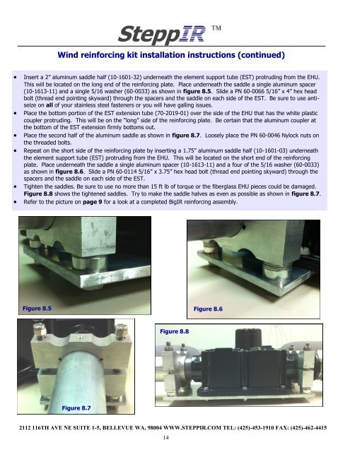
Insert a 2” aluminum saddle half (10-1601-32) underneath the element support tube (EST) protruding from the EHU.<br />
This will be located on the long end of the reinforcing plate. Place underneath the saddle a single aluminum spacer<br />
(10-1613-11) and a single 5/16 washer (60-0033) as shown in figure 8.5. Slide a PN 60-0066 5/16” x 4” hex head<br />
bolt (thread end pointing skyward) through the spacers and the saddle on each side of the EST. Be sure to use antiseize<br />
on all of your stainless steel fasteners or you will have galling issues.<br />
Place the bottom portion of the EST extension tube (70-2019-01) over the side of the EHU that has the white plastic<br />
coupler protruding. This will be on the “long” side of the reinforcing plate. Be certain that the aluminum coupler at<br />
the bottom of the EST extension firmly bottoms out.<br />
Place the second half of the aluminum saddle as shown in figure 8.7. Loosely place the PN 60-0046 Nylock nuts on<br />
the threaded bolts.<br />
Repeat on the short side of the reinforcing plate by inserting a 1.75” aluminum saddle half (10-1601-03) underneath<br />
the element support tube (EST) protruding from the EHU. This will be located on the short end of the reinforcing<br />
plate. Place underneath the saddle a single aluminum spacer (10-1613-11) and a four of the 5/16 washer (60-0033)<br />
as shown in figure 8.6. Slide a PN 60-0114 5/16” x 3.75” hex head bolt (thread end pointing skyward) through the<br />
spacers and the saddle on each side of the EST.<br />
Tighten the saddles. Be sure to use no more than 15 ft lb of torque or the fiberglass EHU pieces could be damaged.<br />
Figure 8.8 shows the tightened saddles. Try to make the saddle halves as even as possible as shown in figure 8.7.<br />
Refer to the picture on page 9 for a look at a completed <strong>BigIR</strong> reinforcing assembly.<br />
Figure 8.5<br />
Figure 8.6<br />
Figure 8.8<br />
Figure 8.7<br />
2112 116TH AVE NE SUITE 1-5, BELLEVUE WA, 98004 WWW.STEPPIR.COM TEL: (425)-453-1910 FAX: (425)-462-4415<br />
14