download manual - Haydon Kerk Motion Solutions
download manual - Haydon Kerk Motion Solutions
download manual - Haydon Kerk Motion Solutions

You also want an ePaper? Increase the reach of your titles
YUMPU automatically turns print PDFs into web optimized ePapers that Google loves.
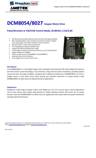
Stepper Motor Drive DCM8054/DCM8027 DatasheetDCM8054/8027 Stepper Motor DrivePulse/Direction or CW/CCW Control Mode, 20‐80VDC, 5.5A/2.8A• Anti‐Resonance provides optimal torque and nulls mid‐range instability• Micro Stepping allows a low resolution step input to produce a highermicro step output, thus offers smoother motor movement• Soft‐start with no “jump” when powered on• TTL compatible and optically isolated input• Support PUL/DIR and Double Pulse modes• 14 selectable resolutions in decimal and binary, up to 51,200 steps/rev• Supply voltage up to +80VDC• Output current up to 5.5A (DCM8054), 2.8A (DCM8027)• Automatic idle‐current reduction• Over‐voltage, over‐current, Short‐circuitDescriptionsThe DCM8054/8027 is a fully digital stepper drive developed with advanced DSP control algorithm based onthe latest motion control technology. It has achieved a unique level of system smoothness, providing optimaltorque and nulls mid‐range instability. Compared with traditional analog drives, DCM8054/8027 can drive astepper motor at much lower noise, lower heating, and smoother movement. Its unique features makeDCM8054/8027 an ideal choice for high performance applications.ApplicationsSuitable for a wide range of stepper motors, from NEMA size 17 to 34. It can be used in various applicationssuch as laser cutters, laser markers, high precision X‐Y tables, labeling machines, CNC router, etc. Its uniquefeatures make the DCM8054/8027 an ideal choice for applications that require both low‐speed smoothnessand high speed performances.<strong>Haydon</strong> <strong>Kerk</strong> <strong>Motion</strong> <strong>Solutions</strong>, Inc. 1500 Meriden Road, Waterbury, CT 06705 USA Tel: 201‐756‐7441 Fax: 203‐756‐8724Email: info.haydonkerk@ametek.com Website: http://www.haydonkerk.comPage 1 of 6Rev June 2012
Stepper Motor Drive DCM8054/DCM8027 DatasheetSpecificationsElectrical SpecificationsParameter Min Typical Max UnitInupt Voltage 20 48 80 VDCOutput Current 0 ‐ 5.5(8054) 2.8 (8027) APulse Input Frequency 0 ‐ 200 kHzPulse Voltage 0 ‐ 5 VLogic Signal Current 7 10 16 mAIsolation Resistance 100 0 0 M ΩOperating EnvironmentCoolingOperating EnvironmentStorage TemperatureWeightNatural Cooling or Forced CoolingEnvironmentAvoid dust, oil fog and corrosive gasesAmbient Temperature0°C – 40°C (32°F – 104°F)Humidity40%RH – 90%RHOperating Temperature (Heat Sink)70°C (158°F) Max‐20°C – 125°C (‐4°F – 257°F)DCM8054: 460g (15.5oz), DCM8027: 350g (12.34oz)Mechanical SpecificationsFront ViewSide ViewFront ViewSide View(a) DCM8054(b) DCM8027<strong>Haydon</strong> <strong>Kerk</strong> <strong>Motion</strong> <strong>Solutions</strong>, Inc. 1500 Meriden Road, Waterbury, CT 06705 USA Tel: 201‐756‐7441 Fax: 203‐756‐8724Email: info.haydonkerk@ametek.com Website: http://www.haydonkerk.comPage 2 of 6Rev June 2012
Stepper Motor Drive DCM8054/DCM8027 DatasheetProtection IndicationsThe green indicator turns on when power‐up. When the drive protection is activated, the red LED blinks periodically(3S) to indicate the error type. For each fault cycle, the red LED turns on for 0.2 second then turns off for 0.3 second.Connectors and Pin AssignmentThe DCM8054/DCM8027 has two connectors, connector for control signals connections and connector for powerconnections. All of them are screw terminals and can be plug/unplug easily.Control Signal ConnectorPin Name I/O Description1 PUL+(+5V) I Pulse Signal: In single pulse (pulse/direction) mode, this input represents pulse signal,2 PUL‐(PUL) I active each rising or falling edge; In double pulse mode (set by inside jumper J2), thisinput represents clockwise (CW) pulse, active both at high level and low level. 4.5‐5Vwhen PUL‐HIGH, 0‐0.5V when PUL‐LOW. For reliable response, pulse width should belonger than 2.5 µs.3 DIR+(+5V) I Direction Signal: In single‐pulse mode, this signal has low/high voltage levels,4 DIR‐(DIR) I representing two directions of motor rotation. In double‐pulse mode (set by insidejumper J2), this signal is counter‐clock (CCW) pulse, active both at high level and lowlevel. For reliable motion response, DIR signal should be ahead of PUL signal by 5 µs atleast. 4.5‐5V when DIR‐HIGH, 0‐0.5V when DIR‐LOW. The motor direction can also bechanged by inside jumper J3. The rotation direction is also related to motor‐driver wiringmatch. Exchanging the connection of two wires for a coil to the driver will reversemotion direction.5 ENA+(+5V) I Enable Signal: This signal is used for enabling/disabling the driver. In default, high level6 ENA‐(ENA) I for enabling the driver and low level for disabling the driver. Usually left UNCONNECTED(ENABLED).<strong>Haydon</strong> <strong>Kerk</strong> <strong>Motion</strong> <strong>Solutions</strong>, Inc. 1500 Meriden Road, Waterbury, CT 06705 USA Tel: 201‐756‐7441 Fax: 203‐756‐8724Email: info.haydonkerk@ametek.com Website: http://www.haydonkerk.comPage 3 of 6Rev June 2012
Stepper Motor Drive DCM8054/DCM8027 DatasheetPower ConnectorPin Name I/O Description1 GND GND Power Ground (Negative)2 +V I Power Supply Input (Positive)20‐80 VDC (recommend leaving room for voltage fluctuation and back‐EMF)3 A+ O Motor Phase A+4 A‐ O Motor Phase A‐5 B+ O Motor Phase B+6 B‐ O Motor Phase B‐DIP Switch SettingsOutput Current (SW1‐SW3)The output RMS current is set by the DIP switches SW1‐SW3 as shown in the following table. Note the actual current is alsorelated to motor velocity.DCM8054 DCM8027 SW1 SW2 SW32.0A 1.0A ON ON ON2.5A 1.3A OFF ON ON3.0A 1.5A ON OFF ON3.5A 1.8A OFF OFF ON4.0A 2.0A ON ON OFF4.5A 2.3A OFF ON OFF5.0A 2.5A ON OFF OFF5.5A 2.8A OFF OFF OFFIdle Current Reduction (SW4)The DIP switch SW4 is used to switch on/off auto‐current current reduction. The auto reduction level is 50% of the run currentsetting.ONOFFSW4 Auto idle current reduction is OFF. Auto idle current reduction is ON.<strong>Haydon</strong> <strong>Kerk</strong> <strong>Motion</strong> <strong>Solutions</strong>, Inc. 1500 Meriden Road, Waterbury, CT 06705 USA Tel: 201‐756‐7441 Fax: 203‐756‐8724Email: info.haydonkerk@ametek.com Website: http://www.haydonkerk.comPage 4 of 6Rev June 2012
Stepper Motor Drive DCM8054/DCM8027 DatasheetMicro Step Resolution (SW5‐SW8)The micro step resolution is set by the DIP switches SW5‐SW8 as show in the following table:Micro step Steps/rev.(for 1.8°motor) SW5 SW6 SW7 SW82 400 ON ON ON ON4 800 ON OFF ON ON8 1600 ON ON OFF ON16 3200 ON OFF OFF ON32 6400 ON ON ON OFF64 12800 ON OFF ON OFF128 25600 ON ON OFF OFF256 51200 ON OFF OFF OFF5 1000 OFF ON ON ON10 2000 OFF OFF ON ON25 5000 OFF ON OFF ON50 10000 OFF OFF OFF ON125 25000 OFF ON ON OFF250 50000 OFF OFF ON OFFSelecting Pulse Active Edge and Control Mode (J1‐J2)There are two jumpers J1 and J2 inside the DCM8027 and DCM8028 specifically for selecting effective pulse edge andcontrol signal mode, as shown in the following figure. Default setting is PUL/DIR mode and upward‐rising edge effective.(a) J1, J2 open circuitPUL/DIR mode and effective at upward-rising edge(b) J1 short circuit, J2 open circuitPUL/DIR mode and effective at downward-falling edge(c)J1 open circuit, J2 short circuitCW/CCW mode and effective at upward-rising edge(d) J1 short circuit, J2 short circuitCW/CCW mode and effective at downward-falling edgePlease note that there is also an internal Jumper J3 which can be used to change the motor direction in PUL/DIR mode.<strong>Haydon</strong> <strong>Kerk</strong> <strong>Motion</strong> <strong>Solutions</strong>, Inc. 1500 Meriden Road, Waterbury, CT 06705 USA Tel: 201‐756‐7441 Fax: 203‐756‐8724Email: info.haydonkerk@ametek.com Website: http://www.haydonkerk.comPage 5 of 6Rev June 2012
Stepper Motor Drive DCM8054/DCM8027 Datasheet<strong>Haydon</strong> <strong>Kerk</strong> <strong>Motion</strong> <strong>Solutions</strong>, Inc. 1500 Meriden Road, Waterbury, CT 06705 USA Tel: 201‐756‐7441 Fax: 203‐756‐8724Email: info.haydonkerk@ametek.com Website: http://www.haydonkerk.comPage 6 of 6Rev June 2012