MSB870 - Mclennan Servo Supplies Ltd.
MSB870 - Mclennan Servo Supplies Ltd.
MSB870 - Mclennan Servo Supplies Ltd.

Create successful ePaper yourself
Turn your PDF publications into a flip-book with our unique Google optimized e-Paper software.
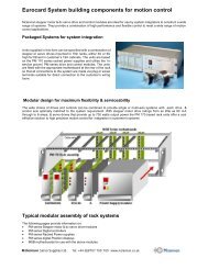
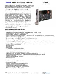
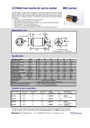
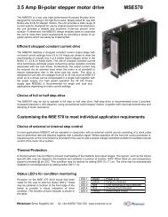
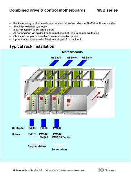
Combined drive & control motherboardsMSB series• Rack mounting motherboards interconnect ‘M’ series drives to PM600 motion controller• Simplifies external connection• Ideal for system users and builders• All connections via solder-free terminations that require no special tooling• Choice of stepper / controller & servo /controller options.• Up to 3 motor axes can be fitted to a single 19 in. rack unitTypical rack installationMotherboards<strong>MSB870</strong> MSB946 MSB910Controller PM600 PM600 PM600Drives PM570 PM542 PM542PM546 PMD 60 SeriesStepper drives<strong>Servo</strong> drives<strong>Mclennan</strong> <strong>Servo</strong> <strong>Supplies</strong> <strong>Ltd</strong>. Tel: +44 (0)8707 700 700 www.mclennan.co.uk
Combined drive & control motherboardsMSB seriesThe latest range of MSB series motherboards have beendesigned to simplify user connections of systems thatincorporate <strong>Mclennan</strong> drive and control modules. Themotherboards are designed to fit at the rear of 19 in.Eurorack and enables both the PM600 controller anddrive to be readily fitted in the rack. All externalconnections are easily made without the need for specialtools. This range of motherboards further simplifiesconnections by providing the interconnection between thecontroller and drive.Controller / drive motherboard options:Stepper Motor control systemsDrive Controller Motherboard<strong>MSB870</strong>MSB946MSB910PM542PM546PM 570PM600MSB 946MSB 870<strong>Servo</strong> Motor control systemsDrive Controller MotherboardPM600controllerPM seriesdrivePM421PMD60 series PM600 MSB 910MSBmotherboardMSB series: simple terminations require no special toolsPower terminals control signal terminalsAll power terminations are made via screw terminalremovable ‘P’ type plugs as shown. Simply insert thepower wire and tighten with a screwdriver as shown.Push downAll control signal terminations are made via ‘TB’ typeclamp terminal blocks as shown. Simply depress thelever with a small screwdriver and insert the signal wireConnection options:• Real time control via computer using RS232 : Fig 1: MSB946 Fig 1b: MSB 870 Fig 1b: MSB910• Connecting over-travel limits & datum signal• Connecting position feedback encoder Fig 2• Connecting Digital I / O Fig 3• Connecting remote stop input Fig 4• Connecting tracker-balls for manual control Fig 5• Connecting joystick for manual control Fig 6• Connecting analogue Input signals Fig 7a: MSB946 & <strong>MSB870</strong> Fig 7b: MSB910• Connecting analogue output signals Fig 8a: MSB946 & <strong>MSB870</strong> Fig 8 b: MSB910• Connecting RS485 communication signals Fig 9• Connecting dual encoders for master / slave operation Fig 10<strong>Mclennan</strong> <strong>Servo</strong> <strong>Supplies</strong> <strong>Ltd</strong>. Tel: +44 (0)8707 700 700 www.mclennan.co.uk
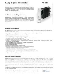
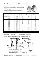
Connecting analogue Output signalsThe PM600 controller may be programmed to provide analogue output signals.The level of the output signal is + 10V..Connections of the analogue output signals to the motherboards are shown belowConnecting analogue Output signals using MSB946 & <strong>MSB870</strong> in stepper systemsOutput 1Fig. 8a+ 10V0V-10V +10V0VTB3TB9TB100V-10V +10VOutput 2Connecting analogue Output signals using MSB810 & servo systemsWhen using the MSB810 with the servo drive units, output 1 is internally connected to the amplifier’s velocity controlsignal input and is therefore not available for external useFig. 8b0VTB3TB9TB10+ 10V0V-10V +10VOutput 2-Connecting an RS485 interfaceAs an alternative to RS232 a RS485 multi-drop interface may be used and connected as shown in Fig 8.Fig. 9ComputerRS485+RS485 -0VTB4TB11<strong>Mclennan</strong> <strong>Servo</strong> <strong>Supplies</strong> <strong>Ltd</strong>. Tel: +44 (0)8707 700 700 www.mclennan.co.uk
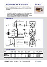
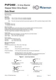
Connecting two encoders for master/ slave <strong>Servo</strong> motor operationThe PM600 controller may be used in systems to synchronise the motor-driven axis to another master axis whenused in ‘<strong>Servo</strong>’ mode. In this mode of operation the <strong>Servo</strong> motor ( slave ) follows a ‘master’ encoder connected to theaxis to be tracked.Step to step synchronisation or a programmable relationship between the master encoder and that fitted to the motor( slave ) can be obtained using the electronic gearbox or electronic cam software in the PM600 controller.When using this technique the encoders are connected as shown in Fig.9 below:Master Encoder5V0VFig. 10A+A-5V0VB+B-TB2TB8MotorEncoderA+A-B+TB3TB9TB10B-I +I -Master encoderMotor<strong>Servo</strong> Motor( slave ) encoderPlease note:The information contained in this data sheet is intended to show the connections required toinstall the drive and controller in a motion system. The user manuals for the drive and thePM600 controller should be consulted for detailed information on the commissioning of thedrive and the controller to ensure that the products are correctly utilised.<strong>Mclennan</strong> <strong>Servo</strong> <strong>Supplies</strong> <strong>Ltd</strong>. Tel: +44 (0)8707 700 700 www.mclennan.co.uk