PT-C Operation Manual - Hitachi Kokusai Electric America, Ltd.
PT-C Operation Manual - Hitachi Kokusai Electric America, Ltd.
PT-C Operation Manual - Hitachi Kokusai Electric America, Ltd.

Create successful ePaper yourself
Turn your PDF publications into a flip-book with our unique Google optimized e-Paper software.
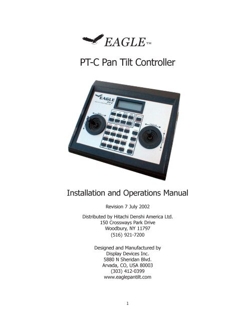
EAGLE<strong>PT</strong>-C Pan Tilt ControllerInstallation and <strong>Operation</strong>s <strong>Manual</strong>Revision 7 July 2002Distributed by <strong>Hitachi</strong> Denshi <strong>America</strong> <strong>Ltd</strong>.150 Crossways Park DriveWoodbury, NY 11797(516) 921-7200Designed and Manufactured byDisplay Devices Inc.5880 N Sheridan Blvd.Arvada, CO, USA 80003(303) 412-0399www.eaglepantilt.com1
Contents1. PRECAUTIONARY STATEMENT .......................................................... pg32. WARRANTY ..................................................................................... pg33. CONTROL PANEL USAGE .................................................................. pg34. FUNCTION DEFINITIONS FOR CONTROL PANEL ................................ pg4CAMERA ............................................................................................. pg4STATUS .............................................................................................. pg4BANK ................................................................................................. pg4SAVE PRESET ...................................................................................... pg4RECALL PRESET .................................................................................. pg4DELETE PRESET .................................................................................. pg5CHAIN ................................................................................................ pg55. SPECIAL FUNCTIONS ....................................................................... pg5WIPER / WASHER................................................................................ pg5LENS EXTENDER CONTROL .................................................................. pg5<strong>PT</strong>-MFA CONTROL ............................................................................... pg5SHOT BOX CONTROL ........................................................................... pg5MODEM CONTROL............................................................................... pg6MULTIPLEXER CONTROL ...................................................................... pg66. FUNCTION MODES .......................................................................... pg6#1 Lens “position” mode...................................................................... pg6#2 Lens “speed” mode. ....................................................................... pg6#3 Preset speed change mode. ............................................................ pg6#4 Scene recall / Preset location functions. ........................................... pg6#5 Focus lock/unlock ........................................................................... pg7#6 Zoom lock/unlock ........................................................................... pg7#7 Pan tilt movement speed control mode. ........................................... pg7#8 Camera controller feedback. ............................................................ pg7#9 Inverted movement operation mode ................................................ pg7#10 Clear all movement limits. ............................................................. pg7#11 Address of pan tilt head. ............................................................... pg8#12 Set lens type. ............................................................................... pg8#13 Set left pan limit. .......................................................................... pg8#14 Set right pan limit. ........................................................................ pg8#15 Set up tilt limit. ............................................................................ pg8#16 Set down tilt limit. ........................................................................ pg87. PAN-TILT OPERATIONS .................................................................... pg98. POWER REQUIREMENTS / PIN CONFIGURATION ............................. pg10FREQUENTLY ASKED QUESTIONS / SETUP PROBLEMS ......................... pg112
The Eagle <strong>PT</strong>-C control system allows the control of all of the pan-tilt heads from Eagle. Itis available in a standard desktop configuration. It provides attitude control of the pan tilthead as well as, zoom, focus and iris control of camera lenses; control of an optional environmentalhousing, and has special function keys that can be utilized for other needs. Inconjunction with the <strong>PT</strong>-CC camera control it will allow remote control of the <strong>Hitachi</strong> HVC,HVD, and Z series of cameras.1. PRECAUTIONARY STATEMENTImproper settings and connections of the <strong>PT</strong>-C may cause damage to the pan tilthead, the camera, and the lens being used. Please read all of the following documentationbefore attempting the installation and configuration of these systems. If any ofthe instructions are unclear to you, call your servicing dealer or <strong>Hitachi</strong> before proceedingfor clarification. Failure to correctly configure and install these systems maycause damage to the equipment, and will void the warranties. Please make surebefore connecting or disconnecting any cables that the power supplies are turnedOFF.2. WARRANTY<strong>Hitachi</strong> Denshi <strong>America</strong>, <strong>Ltd</strong>. warrants to the original customer that each unit shall be freefrom malfunction due to defective workmanship or component failure for a period of ONEYEAR from the original date of delivery to the customer. For service under the warrantyperiod, return authorization must be obtained before returning the product. This warrantydoes not apply to finish or appearance items, to malfunction due to abuse or operation inviolation of published operating specifications, or to failures caused by improper connections,modifications, alterations, or other unauthorized repairs. This warranty does not coverlabor or shipping costs for removal and/or reinstallation of equipment under warranty.Under no circumstances shall <strong>Hitachi</strong> Denshi <strong>America</strong>, <strong>Ltd</strong>. or Display Devices, Inc., theirowners or employees be liable to you for any special damages, including any lost profits,lost savings, or other incidental or consequential damages, or for any claim by any otherparty.3. CONTROL PANEL USAGEThe <strong>PT</strong>-C control panel has a 24 character by 2 line LCD display for status feedback of thecurrent operation. Most of the individual functions for setup of the pan-tilt system havefeedback that is shown by the LCD display.Note that the graphic overlay on the control panel has information in both black text belowthe buttons, and in red text above the buttons. This is to help signify that the red text is theaction of the FUNCTION key (outlined in red at the top right of the button panel) and thechosen button. For example, to enter LENS POSITION mode, touch FUNCTION, then the1 button.If desired, you can leave the FUNCTION mode by hitting the FUNCTION key twice. Example;if you have already touched the FUNCTION key with the intention of creating a newpreset, then change your mind, hit the FUNCTION key again. The display will clear.Individual control joysticks allow adjustment of the pan tilt head and lens’ zoom and focus3
control. The pan tilt head is vector solving, i.e., it will move diagonally instead of just movinghorizontally and vertically. It is also speed sensitive; deflect the joystick a small amount andthe head moves slowly; deflect the joystick a large amount and the head moves quickly.The same speed sensitive control applies to the lens’ zoom and focus features in themanual, “speed” mode only.4. FUNCTION DEFINITIONS FOR CONTROL PANELNOTE: when using the keypad, you must use the number key for the specific function youwish to access; for example, to use FUNCTION 16, hit the FUNCTION button, then the 16key. Do not use the separate 1 and 6 keys--this will not work!CAMERASelects the camera / head combination to be moved. Select the CAMERA button followedby the number of the camera you wish to control. For example, to control camera 1, press“CAMERA” , then the 1 key. The display will show “CAMERA 1”. Select the CAMERA thenALL button if you wish to move ALL camera heads. Please note that for safety reasonswhen CAMERA, ALL is selected, you may not clear travel limits (FUNCTION 10).STATUSThis button will display the status of the current head selection on the status bar at the topof the program window. It is useful when trying to track a communications problem in theinitial setup of the system. If the communications are working correctly, the display shouldreturn an “OK” when the STATUS button is pushed. Note that this will only report the statusof a single station; it will not work if CAMERA / ALL is selected. If an unprogrammed camerais selected, no report will be returned; for example, if the status is asked for on camera#5 in a four camera system, etc.BANKThe BANK button is to be used for switching between two “banks” of up to 16 cameraseach. This allows the <strong>PT</strong>-C to control up to 32 different pan tilt heads. Press the BANKbutton once; the LCD display will readout “BANK 2”. Now enter the camera number in thesecond bank that you wish to control, keeping in mind that the number you enter is addedto 16. For example, enter BANK, then 1. The display will read CAMERA 17. If you enterBANK, 10, the display will read CAMERA 26.SAVE PRESETMove the left joystick up, down, left, or right for positioning the head, manually aiming theshot the way you desire. Select FUNCTION 1 to begin the lens position mode (Fujinon /Canon telecon lenses only). Use the zoom and focus in/out joystick to select the field ofview as desired. YOU MUST ZOOM AND FOCUS TO SET UP YOUR SHOT AFTER EN-TERING THE POSITION MODE !!. If you set up your zoom and focus before entering thePOSITION mode, the lens will not report where it is in its’ zoom and focus range to thesoftware, and the lens preset will not be stored. Press the SAVE PRESET button followedby the number of the preset you wish to call it. Up to 16 presets may be saved for eachindividual pan tilt head.RECALL PRESET4
Push this button followed by the number of the preset you wish to recall.DELETE PRESETPush this button followed by the number of the preset you wish to delete.CHAINPresets may be linked together with this function. It will automatically recall presets atintervals of your choosing. First, recall the preset number you wish to start from; even if youare at this preset currently, you must recall it in order to use the CHAIN function. PressCHAIN and the number of the next preset; Press TIME and enter the wait time at thispreset in seconds from 1 to 16. Repeat this process for as many presets as desired to belinked. Recall the first preset and the CHAIN will start.5. SPECIAL FUNCTIONSThe following is list of special functions that are used in combination with optional accessoriesof the Eagle Pan Tilt system.WIPER / WASHERThis button controls the window wiper of the optional <strong>PT</strong>-EE-L environmental housing. Thisbutton is only functional with the <strong>PT</strong>E environmental head. When pressed once, the wiperwill activate for about three seconds. To activate the washer, press FUNCTION, WIPER.The pump of the optional <strong>PT</strong>-WW-1 will squirt a stream of liquid onto the window of thehousing. It may be necessary to hit FUNCTION, WIPER several times before liquid squirtsonto the window; this is to prime the pump and liquid line.LENS EXTENDER CONTROLO<strong>PT</strong>ION APressing only the O<strong>PT</strong> A button toggles a lens’ 2x extender on or off; this is an option ofsome special Canon and Fujinon lenses, and does not work with any lens.<strong>PT</strong>-MFA CONTROLO<strong>PT</strong>ION BPressing only the O<strong>PT</strong> B button will work with the optional <strong>PT</strong>-MFA multifunction adapter toconfigure the relays on the <strong>PT</strong>-MFA; see the detailed manual included with the <strong>PT</strong>-MFA forexact operation.SHOT BOX CONTROLO<strong>PT</strong>ION CPressing only the O<strong>PT</strong> C button will control various features of the <strong>PT</strong>-SB “shot box”, motioncontrol recorder. See the detailed manual included with the <strong>PT</strong>-SB for exact operation.5
MODEM CONTROLFUNCTION, O<strong>PT</strong>ION A, B, CPressing FUNCTION, then O<strong>PT</strong>ION A, B, or C are three commands used for dialing controlof the optional <strong>PT</strong>-AAM modem control system. FUNCTION, O<strong>PT</strong>ION A dials apreprogrammed number from memory. FUNCTION, O<strong>PT</strong>ION B hangs up a modem dialedcall, and FUNCTION, O<strong>PT</strong>ION C is used to enter and save the phone numbers to bedialed. Please see the detailed operating instructions included with the <strong>PT</strong>-AAM system.MULTIPLEXER CONTROLFUNCTION, CAMERAPressing FUNCTION, CAMERA will bring up a menu on the LCD for setting and releasingexclusive control of pan-tilt heads attached to the <strong>PT</strong>-MP-1 multiplexer unit. Press 1 toRESERVE HEAD, press 2 to RELEASE HEAD. When you press either 1 or 2, the displaywill change to RESERVE <strong>PT</strong> or RELEASE <strong>PT</strong>. It is now waiting for you to input the addressof the pan tilt head you want to control. Enter this address number, and the display willchange again, asking which controller port on the <strong>PT</strong>-MP-1 you are plugged into. Ports onthe multiplexer are labeled 1 through 6; enter the number of the port you are connected to.Once this is done, the LCD display will clear itself after 3 to 4 seconds.6. FUNCTION MODESSelect the FUNCTION button then the following numbers to run the desired function;#1 Lens “position” mode.FOR TELECONFERENCING SERVO DRIVE LENSES ONLYEnter this mode to set lens zoom and focus presets. See section “SAVE PRESET” abovefor details on the operation of this function. The LCD display will read POSITION MODE.#2 Lens “speed” mode.FOR TELECONFERENCING SERVO DRIVE LENSES ONLYThis is the normal lens operating mode. The LCD will read SPEED MODE momentarily.#3 Preset speed change mode.In conjunction with function 7 below, this function allows changing preset speeds to differentvalues than were originally chosen. For example, travel to preset 3 was originally set tospeed 1(high speed). If you now want to change travel speed to this preset to 2 (normal),recall preset 3, then enter FUNCTION, 3; the LCD will read PRESET SPEED. Then press 2for normal speed. The LCD display will clear itself after 3 to 4 seconds.#4 Scene recall / Preset location functions.Dependent upon the camera being used, i.e., if using capable <strong>Hitachi</strong> cameras, SCENEfiles can be stored on the camera controller and recalled in conjunction with a specificlocation preset. This could be useful if the scene has multiple shots to be setup, under6
different lighting conditions. First, the scene files must be set up AND STORED using the<strong>PT</strong>-CC camera controller. Next, decide which position preset you want to link to whichscene file. For our example, let’s use position preset 3, and link it to scene file 1. RECALLposition preset 3 (as described in section 5.4), then hit FUNCTION, 4, and the LCD displaywill show CAMERA SCENE. Then press number 1, specifying the recall of scene file 1.This will now link the position preset 3 and the scene file 1 together. In order to make anychanges after saving this information, you must either resave the SCENE file, or resave ordelete the position preset 1. The LCD will clear itself after 3 to 4 seconds.#5 Focus lock/unlockThis is a toggling function that will lock and unlock the FOCUS axis of the joystick. This isconvenient if you have a shot setup that the focus will not need to be changed, but youwish to zoom in and out to change the shot. This will prevent any accidental changes infocus while zooming. Press FUNCTION, then 5, then 1 to LOCK or 2 to UNLOCK. TheLCD display will read FOCUS LOCKED and FOCUS UNLOCKED.#6 Zoom lock/unlockThis is a toggling function that will lock and unlock the ZOOM axis of the joystick. This isconvenient if you have a shot setup that the zoom setting will not need to be changed, butyou wish to focus near or far to make the shot. This can also be used to prevent any unwantedor unauthorized changes. Press FUNCTION, then 6, then 1 to LOCK or 2 to UN-LOCK. The LCD display will read ZOOM LOCKED and ZOOM UNLOCKED.#7 Pan tilt movement speed control mode.This allows the overall speed of the pan and tilt motion to be changed. Press the FUNC-TION, 7; the display will read HEAD SPEED. Then press 1 for HIGH speed, 2 for NOR-MAL, and 3 for SLOW. Any pan and tilt presets will also store the speed originally chosenhere. For example, you can set a preset position using two different speeds, and recallthem at different times depending on the effect desired. NOTE: lens zoom and focus presetsare always recalled at full speed, this is not changeable. The LCD will clear itself after3 to 4 seconds.#8 Camera controller feedback.If using the <strong>PT</strong>-C standalone pan tilt controller with the <strong>PT</strong>-CC camera controller, this will letthe <strong>PT</strong>-C know it has a camera controller installed to talk to. Press FUNCTION, 8--Thedisplay will toggle between CC ON and CC OFF.#9 Inverted movement operation mode(up/down, left/right reversed). This function is used when the pan/tilt is to be ceilingmounted instead of tripod mounted, and it reverses the movement directions of the pan tilthead. This can be set individually on a head by head basis so that if a mix of upright andinverted heads are being used in the same room, they can be configured such that they allmove the same direction. Please note that with the current level of software, no LCD feedbackis presented.#10 Clear all movement limits.7
This function will eliminate all position limits that may have been set to prevent excesstravel. This clearing is temporary only; when power is reset, the previous limits will returnunless you set new limits. Hit FUNCTION, then the 10 key; the LCD display will prompt youto press 1 to clear limits, 2 to cancel. Please note that this function only works with a singleaddressed head for safety reasons. If CAMERA, ALL is selected, you cannot clear movementlimits. This is to prevent the accidental clearing of limits from other heads on thesame RS 485 line.#11 Address of pan tilt head.This is set by the factory to 1 when shipped. If a change is required, simply enter FUNC-TION, the 11 button; the LCD display will read ADDRESS. Then click the number you wishto set the head to. Note that this will set the number for all heads on the RS-485 comm line;you must disconnect the power or communication for all the heads except the one youwish to address, otherwise all the powered heads will be set to the same address. Notethat the readdressing procedure will only work if you know the number the head is currentlyset to; if you don’t know the number, first select CAMERA, ALL. This will allow you to talk toany head that is correctly wired up.#12 Set lens type.This is set by the factory when ordered for your specified lens type; 1 is for Rainbow andother CCTV type lenses, 2 is for Fujinon telecon and Canon telecon lenses set to Fujinonmode. The LCD display will read LENS TYPE.#13 Set left pan limit.Limits are preset at the factory to 50 degrees each up and down, and about 160 degreeseach left and right. Change the limit settings if you want to change these amounts; this isuseful to set up cameras such that they can not get shots of the wall behind the camera,the ceiling above the camera, the floor directly below the camera, etc. Also, limits may needto be set differently for your particular application; e.g., if a ceiling mount adapter is used,you may need to set a limit for tilting upwards to prevent lens contact with the ceiling, etc.The LCD display will read SET LEFT LIMIT.Please note that dependent on the setting of FUNCTION 9, the INVERT command, that insome circumstances LEFT LIMIT will actually be RIGHT LIMIT; UP LIMIT will be DOWNLIMIT. If you accidentally set a limit incorrectly, simply clear it by hitting FUNCTION, 10, 1(CLEAR ALL LIMITS). Limits may not be cleared individually, but as a whole.#14 Set right pan limit.See above Function 13#15 Set up tilt limit.See above Function 13#16 Set down tilt limit.8
See above Function 137. PAN-TILT OPERATIONSBe sure to follow all of the installation instructions included with the Eagle pan tilthead before starting to use this controller !!First, select the address of the head you wish to control. Since up to 31 heads may be on asingle RS-485 line, you must choose the correct one to control. Select CAMERA, then thenumber of the head to be controlled. Head addresses can be changed as described in theprevious section for Function 11.If this is the first time use of the system, the limits of pan tilt movement must be set now.Begin by entering FUNCTION 10, Clear all movement limits. This function will eliminate allposition limits that have been set at the factory to prevent excess travel. This clearing istemporary only; when power is removed and then restored, the previous limits will returnunless you have set new limits. This will erase any limits previously set by the factory duringtesting.Next, set the limits of travel as desired. Use the FUNCTIONs 13 through 16, for left, right,up, and down limit setting. Remember, that the pan tilt head has a range of pan of 360° (leftor right 180°), and a tilt range of 360° (up or down 180°); it cannot turn more than a fullcircle. There are end travel stops programmed into the head to prevent traveling more thanthese amounts.Make sure when cabling the system that enough cable slack is included to prevent damageto the pan-tilt connectors and camera and lens connectors. The motors in the head arevery strong, and will easily rip a connector out of its’ socket. Once the travel limits are set,normal usage of the pan tilt system may begin.Start by entering the location number you wish to control. Use the keypad and push CAM-ERA, then select the number from 1 to 16. NOTE: Pan tilt head address numbers havebeen initialized at the factory to number 1; if you need to change them in the field, seeFUNCTION 11, Setting pan tilt head address.9
8. POWER REQUIREMENTS / PIN CONFIGURATIONThe <strong>PT</strong>-100 series of pan tilt heads require 24 volts DC power. Maximum draw is approximately3 amps; average current draw in operation is 1.5 amps. The head will provide powerfor camera / lens combinations drawing less than 2 amp @ 12 VDC; if the camera / lensdraws more than this, a separate external camera power supply is required. To help reducepower drop, it is common practice to run 4 conductors for power and tie two conductorstogether at the end, thus doubling the effective current carrying capability. Here is a chartwith recommended AWG for different distances ( at 77°F ):Distance in feetAWG20 2850 26100 22200 18500 161000 12Here are tables of pin configurations for the two D-sub connectors on the controller rear:AT EDGE OF <strong>PT</strong>-CDB-9 female connector(interconnect to <strong>PT</strong>-CC)PIN 1TO <strong>PT</strong>-CC PIN 1IN CENTER OF <strong>PT</strong>-CDB-9 male connectorRS-485 networkPIN 1--NO CONTAC TPIN 2 TO <strong>PT</strong>-CC PIN 2 PIN 2--RS 485 LINE 1PIN 3 TO <strong>PT</strong>-CC PIN 3 PIN 3--RS 485 LINE 2PIN 4PIN 5PIN 6TO <strong>PT</strong>-CC PIN 4TO <strong>PT</strong>-CC PIN 5TO <strong>PT</strong>-CC PIN 6PIN 4--NO CONTAC TPIN 5--RS 485 GROUN DPINS 6-9--NOT USEDPower for the controller is 12VDC, 500 mA, supplied by the included wall transformer withattached connector. DO NOT USE ANY OTHER POWER TRANSFORMER FOR THISCONTROLLER AS SEVERE DAMAGE MAY RESULT!10
FREQUENTLY ASKED QUESTIONS / SETUP PROBLEMSMy pan tilt head was working, but now has stopped responding. I still have a picturefrom the camera, but have no control. What happened?A: You are either trying to control the wrong head number, or the head has accidentallybeen readdressed to an unknown number, or the serial communications have failed. If youare certain that you are trying to control the correct head, follow this procedure to regaincontrol.1. On the <strong>PT</strong>-C controller, select CAMERA, ALL. This will talk to any head on the line. Try tomove the head up, down, left, or right. If it responds, then you have good communications.Follow the procedure on page 8 to readdress the head to the number you want it to be.2) If it doesn’t respond, then check the serial wiring path from the controller to the head(s).If you have multiple heads, and the other heads work correctly, then your wiring path ismost likely correct, but should still be tested. Try moving the non-working head to a knownworking location and retesting.3) The red LED on the front panel of the head is for troubleshooting and status. If a head iscorrectly wired and addressed, when you move the joystick, the LED will glow solid, withsome modulation seen as you move the joystick. If the LED comes on solid upon power up,then the RS-485 ground and one of the comm lines are reversed. Check your wiring again.If the LED never comes on solid, but only flickers, then either the head is hearing traffic foranother head, or the RS-485 A & B comm lines are reversed. If you are certain the head isaddressed properly, then swap the A&B comm lines and test again.If it still doesn’t work at a known good location, you have swapped the comm lines, andtried readdressing, then the head may be faulty. Contact Eagle tech support at (303) 412-0399 or www.eaglepantilt.com.My lens control isn’t working correctly; the lens goes to one end of its’ range andwont move.The lens type has been set incorrectly. The Eagle pan tilt system is capable of using eitherservo drive teleconferencing lenses, or DC drive C-mount lenses. If set to the wrong type,this symptom will result. Verify the type of lens you are using and check the lens type asshown on page 8.I have the accessory <strong>PT</strong>-CC camera controller. I used to be able to change the camerasettings remotely, but now it has stopped working. Why?Verify that the interconnect cable between the <strong>PT</strong>-C and <strong>PT</strong>-CC controllers is secure. Next,check to make sure the <strong>PT</strong>-CC is enabled for use by the <strong>PT</strong>-C. Touch FUNCTION, 8. TheLCD display will read CC ON, meaning it is enabled, or CC OFF meaning it is disabled. If itfirst said CC ON, that means that it was in the off state, and you just turned it on. Check forcamera control features now. If you still don’t have camera control, make sure that thecamera control cable from the rear of the pan tilt head to the rear of the camera is pluggedin. If it is, then camera control may be faulty; contact Eagle tech support.11
I am trying to set up a preset shot, but the head isn’t returning to the correct positionor zoom/focus setting.This could be caused by a number of things. First, if using a teleconferencing lens, makesure you are going into POSITION mode (FUNCTION,1) before trying to set the preset. Ifyou are not in POSITION mode, the lens’ zoom and focus settings cannot be memorized.Also, the pan and tilt joystick must be moved for the head’s position settings to be recorded.If the zoom and focus settings are retrieved correctly, but the head is landing high or lowwhen recalling, then the weight balance of the camera/lens assembly is probably off fromfront to rear. The assembly must be centered from front to rear to provide accurate recall; ifit is balanced too far front, then it will probably be low in recalling presets above horizontal.If balanced too far rear, it will be high in recalling presets above horizontal. Remove thecamera/lens assembly as needed in order to check the balance, and replace it in the correctposition.IF YOU ARE EXPERIENCING A PROBLEM NOT COVERED HERE, OR YOU HAVETROUBLE UNDERSTANDING THESE SOLUTIONS, PLEASE CONTACT EAGLE TECHSUPPORT AT (303) 412-0399, M-F 8AM TO 5PM.12