Create successful ePaper yourself
Turn your PDF publications into a flip-book with our unique Google optimized e-Paper software.
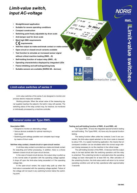
<strong>Limit</strong>-<strong>value</strong> switch,input AC-voltage• Straightforward application• Suitable for severe operating conditions• Compact construction• Switching point freely adjustable by drum scale• Anti-tamper seal for drum scale• Meet high EMC-requirementsrequirements• Volt-free output as make-and-break contact or make-contact• Open-circuit or closed-circuit variants available• Test function to simulate an increased sensor signalwithout critical machine loading (RW5...-S)• Self-holding function of output relay (RW5...-S)• Operating characteristics displayed by integrated LEDs• Flame-inhibiting and self-extinguishing body• Suitable sensors are available (NORIS GE.. devices)21Schaltbereich:Switch.Range:Umgeb. Temp:Amb. Temp:18...32V0...60V AC-20°C...70°C360...60V AC4 7TS254-104Typ: RW54-ARevision:A1,0A 30V/DC0,5A 60V/DC0,2A 220V/ACImageRW54-APN.120321 Ta.02-24205RW5..<strong>Limit</strong>-<strong>value</strong> <strong>switches</strong><strong>Limit</strong>-<strong>value</strong> <strong>switches</strong> of series 5<strong>Limit</strong> <strong>value</strong> <strong>switches</strong> of the series 5 are designed to monitor andprocess electric measured variables.Working principle: When the actual <strong>value</strong> of the measuring signalsupplied reaches the setpoint, the built-in relay will operate. Theswitching status of the relay contact may, for instance, be monitoredor individually processed by a machine controller.General notes on Type RW5..Description RW5..• Designed to monitor an alternating voltage• Various devices available for optimal matching toinput signal• Switching point settings possible over complete input rangeby means of drum scaleVolt-free relay contact, closed-circuit or open-circuit versionA volt-free relay contact is provided as a make-and-break contactfor outputting and further processing. In addition, there is a choicebetween closed-circuit and open-circuit devices.In the case of closed-circuit devices, the output relay is pulled upin the normal state of operation with the operating voltage applied.It drops off upon the limit-<strong>value</strong> being exceeded or if the operatingvoltage fails.In the open-circuit variant, the output relay pulls up when thelimit-<strong>value</strong> is exceeded with the operating voltage applied. Failure ofthe voltage will not result in any switching function below the switchingpoint.Testing and self-holding function of RW5..-S and RW5..-A2The Types RW5..-S have the integrated special functions testingand self-holding. The Types RW5..-A2 have only the special functiontesting.The testing function offers while the contacts 2 and 5 are connected,the limit-<strong>value</strong> signal selected on the drum scale is loweredby about 15%. In a speed monitoring application, this means that anoverspeed condition can be simulated within the normal range withoutit being necessary to run the machine in the critical range.The self-holding function of the RW5..-S devices hold the outputrelay to be kept latched after the switching operation until the relayis unlatched. The unlatching function is activated when the operatingvoltage as been interrupted for at least 500 ms. After activation ofthe unlatching function, the limit-<strong>value</strong> switch will return to its normaloperating condition and will be fully operational after approximately3 secondsDB-RW5
Technical DataSeries RW5.., RW5..-SOperating voltage U O=12 ... 32 V/DC, U R=24 V/DCRipple< 20% U OReverse voltage protection IntegratedOvervoltage2.5 times U Rup to 2 msVoltage drops100% up to 10 msPower consumption Approx. 50 mA (24 V/DC)Galvanic isolation Between input signal and operating voltageInput signalAC-voltage, NORIS tacho-generator GEInput overloading < 1.5 times maximal inputInput resistanceRW53.. approx.30 kΩ, RW54.. approx.60 kΩ, RW55.. approx.90 kΩOutput contactVolt-free make-and-break contact, closed circuit or open circuit (RW5..)Volt-free NOC, closed circuit or open circuit (RW5..-A2, RW5..-S)Maximal switching capacity 30 W (1 A at 30 V/DC; 0.5 A at 60 V/DC) 40 W (0.2 A at 220 V/AC)Switching pointAdjustable on tamper-proof drum scale between 2 … 20 V/AC forRW53.., 6 ... 60 V/AC for RW54.., 9 ... 90 V/AC for RW55..Reproducibility < +/- 0.2%Linearity of scale < +/- 1.5%Hysteresis Approx. 1.5%Test functionConnect 2/5 to lower switching point approx. 15% (only RW5..-S/RW5..-A2)Self-holding function Relais is held till operating voltage is interrupted min. 500 ms (RW5..-S)Error class IEC51-1 1.5%Temperature sensitivity < +/- 0.1% je 10 °KVoltage sensitivity < +/- 0.1% for 10% change in operating voltageReaction time< 300 msMeasuring suppression Approx. 2 s after turning on the operating voltageVibration resistance IEC60068-T2-6 15g increased strain, characteristic 2 (10 …100 Hz)Shock resistance (impact) DIN IEC60068-T2-27 300 m/s² with 18 ms dwell timeClimatic testIEC60068-T2-30Operating temperature -20 °C ... +70 °CShelf temperature -45 °C ... +85 °CHumidityRH 96% maximumESDIEC61000-4-2 +/- 8 kVElectromagnetic field IEC61000-4-3 10 V/m f=10 kHz ... 2000 MHz, 80% AM @ 1 kHz10 V/m f=900 +/- 5 MHz, 50% AM @ 200 Hz10 V/m f=1800 MHz +/- 5 MHz, 50% AM @ 200 HzBurstIEC61000-4-4 +/- 2 kV supply +/- 1 kV sensorSurge IEC61000-4-5 sym. +/- 1 kV (R i=2 Ω) asym. +/- 2 KV (R i=2 Ω)HF-susceptibilityIEC61000-4-6 3 V pp80% AM @ 1 kHz f=0.01 ... 100 MHzLF- susceptibility IEC60553 3 V pp0.05 ... 10 kHzInterference field intensity Basis CISPR 16-1, 16-2 reduced characteristicConnection DIN46244 flat connector, gold-plated A6.3 x 0.8Protection classDIN EN60529 Body IP20, terminals IP00MountingSnap-fit on top-hat channel or G-channelInstalled positionAnyBody materialThermoplastic polyester, green, fire protection class V0Weight55 gStandard supply CE requirements complied with, DIN EN 61000-6-2, DIN EN 61000-6-4,DIN EN 50155, approved by GL, LR, DNVType key / variantsInput range: 2 ... 20 V/AC 6 ... 60 V/AC 9 ... 90 V/ACMake-and-break in closed circuit RW53 RW54 RW55Make-and-break in open circuit RW53-A RW54-A RW55-ANOC in open circuitRW53-S RW54-S RW55-Swith test function andself-holding functionNOC in open circuitRW53-A2 RW54-A2 RW55-A2with test functionDevice codesR <strong>Limit</strong>-<strong>value</strong> switchInput signalW AC-voltageType series5 Type 5Input range3 2 ... 20 V/AC4 6 ... 60 V/AC5 9 ... 90 V/ACVarianteOutput contact as make-and-break contact in closed circuit- A Output contact as make-and-break contact in open circuitA2 Output contact as NOC in open circuit with test function- S Output contact as NOC in open circuit with test function anself-holding functionR W 5 3 - A (RW53-A)Other Data12+-3 ~6V4 ~ 7Connetion make-and-break RW5.., RW5..-A12LED green+-3 ~V4 ~RW5..70Anti-tamper sealLED redG-channel TS32 to DIN EN50035Top-hat channel TS35 to DIN EN 500226/7RW5..-A5/6RW5..-ATest6/7RW5..5/6RW5..LEDgrünU < switch point - x -U > switch point x x xx = contact closed / LED lighting- = contact open / LED outo = LED flashingLEDrotU < switch point x - - x x -U > switch point - x x - x xRW5..-S6/7RW5..-SConnetion NOC RW5..-S, RW5..-A2Relais position and LED codeLEDgrünLEDrot4617,515175567NORIS Automation GmbHMuggenhofer Strasse 9590429 NurembergGermanyTel.: +49 911 3201-220Fax: +49 911 3201-150sales@noris-group.comwww.noris-group.comVersion 01.01: 03/2012Changes reserve


