MIPI M-PHY Transmitter and Receiver Test Solutions - M ... - Tektronix
MIPI M-PHY Transmitter and Receiver Test Solutions - M ... - Tektronix
MIPI M-PHY Transmitter and Receiver Test Solutions - M ... - Tektronix

You also want an ePaper? Increase the reach of your titles
YUMPU automatically turns print PDFs into web optimized ePapers that Google loves.
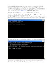
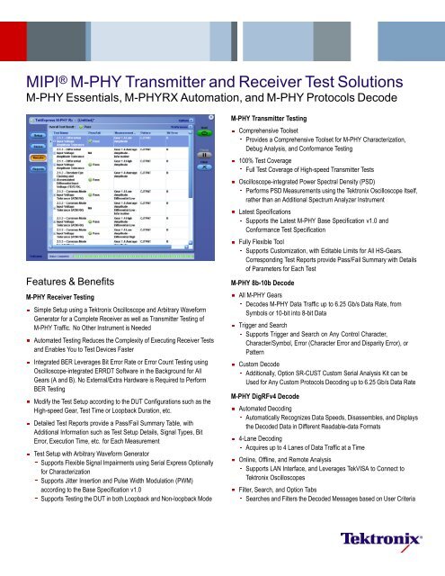
<strong>MIPI</strong> ® M-<strong>PHY</strong> <strong>Transmitter</strong> <strong>and</strong> <strong>Receiver</strong> <strong>Test</strong> <strong>Solutions</strong>M-<strong>PHY</strong> Essentials, M-<strong>PHY</strong>RX Automation, <strong>and</strong> M-<strong>PHY</strong> Protocols DecodeFeatures & BenefitsM-<strong>PHY</strong> <strong>Receiver</strong> <strong>Test</strong>ingSimple Setup using a <strong>Tektronix</strong> Oscilloscope <strong>and</strong> Arbitrary WaveformGenerator for a Complete <strong>Receiver</strong> as well as <strong>Transmitter</strong> <strong>Test</strong>ing ofM-<strong>PHY</strong> Traffic. No Other Instrument is NeededAutomated <strong>Test</strong>ing Reduces the Complexity of Executing <strong>Receiver</strong> <strong>Test</strong>s<strong>and</strong> Enables You to <strong>Test</strong> Devices FasterIntegrated BER Leverages Bit Error Rate or Error Count <strong>Test</strong>ing usingOscilloscope-integrated ERRDT Software in the Background for AllGears (A <strong>and</strong> B). No External/Extra Hardware is Required to PerformBER <strong>Test</strong>ingModify the <strong>Test</strong> Setup according to the DUT Configurations such as theHigh-speed Gear, <strong>Test</strong> Time or Loopback Duration, etc.Detailed <strong>Test</strong> Reports provide a Pass/Fail Summary Table, withAdditional Information such as <strong>Test</strong> Setup Details, Signal Types, BitError, Execution Time, etc. for Each Measurement<strong>Test</strong> Setup with Arbitrary Waveform GeneratorSupports Flexible Signal Impairments using Serial Express Optionallyfor CharacterizationSupports Jitter Insertion <strong>and</strong> Pulse Width Modulation (PWM)according to the Base Specification v1.0Supports <strong>Test</strong>ing the DUT in both Loopback <strong>and</strong> Non-loopback ModeM-<strong>PHY</strong> <strong>Transmitter</strong> <strong>Test</strong>ingComprehensive ToolsetProvides a Comprehensive Toolset for M-<strong>PHY</strong> Characterization,Debug Analysis, <strong>and</strong> Conformance <strong>Test</strong>ing100% <strong>Test</strong> CoverageFull <strong>Test</strong> Coverage of High-speed <strong>Transmitter</strong> <strong>Test</strong>sOscilloscope-integrated Power Spectral Density (PSD)Performs PSD Measurements using the <strong>Tektronix</strong> Oscilloscope Itself,rather than an Additional Spectrum Analyzer InstrumentLatest SpecificationsSupports the Latest M-<strong>PHY</strong> Base Specification v1.0 <strong>and</strong>Conformance <strong>Test</strong> SpecificationFully Flexible ToolSupports Customization, with Editable Limits for All HS-Gears.Corresponding <strong>Test</strong> Reports provide Pass/Fail Summary with Detailsof Parameters for Each <strong>Test</strong>M-<strong>PHY</strong> 8b-10b DecodeAll M-<strong>PHY</strong> GearsDecodes M-<strong>PHY</strong> Data Traffic up to 6.25 Gb/s Data Rate, fromSymbols or 10-bit into 8-bit DataTrigger <strong>and</strong> SearchSupports Trigger <strong>and</strong> Search on Any Control Character,Character/Symbol, Error (Character Error <strong>and</strong> Disparity Error), orPatternCustom DecodeAdditionally, Option SR-CUST Custom Serial Analysis Kit can beUsed for Any Custom Protocols Decoding up to 6.25 Gb/s Data RateM-<strong>PHY</strong> DigRFv4 DecodeAutomated DecodingAutomatically Recognizes Data Speeds, Disassembles, <strong>and</strong> Displaysthe Decoded Data in Different Readable-data Formats4-Lane DecodingAcquires up to 4 Lanes of Data Traffic ataTimeOnline, Offline, <strong>and</strong> Remote AnalysisSupports LAN Interface, <strong>and</strong> Leverages TekVISA to Connect to<strong>Tektronix</strong> OscilloscopesFilter, Search, <strong>and</strong> Option TabsSearches <strong>and</strong> Filters the Decoded Messages based on User Criteria
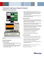
<strong>MIPI</strong> ® M-<strong>PHY</strong> <strong>Transmitter</strong> <strong>and</strong> <strong>Receiver</strong> <strong>Test</strong> <strong>Solutions</strong> — M-<strong>PHY</strong> Essentials, M-<strong>PHY</strong>RX Automation, <strong>and</strong> M-<strong>PHY</strong> ProtocolsDecodewill be generated in .MHT format. The results of the test will also be storedin an Excel .XLS file that can be used for further data analysis. Included inthe test report are the configuration settings for the test equipment, testexecution times, <strong>and</strong> comments for each test.Counting Bit Errors using Oscilloscope Error Detector, in DUT <strong>Receiver</strong> Loopback.Loopback Initiation <strong>and</strong> RetentionBefore the <strong>Receiver</strong> test can start, the device under test must be put in theproper test mode, called Loopback, where the DUT loops the incomingsignal at Rx directly to the Tx port. Once the Loopback is set on the DUT,then the Arbitrary Waveform Generator sends a Burst mode signal withrecommended patterns for all measurements. The M-<strong>PHY</strong>RX Automationsoftware will allow the user to configure the Loopback settings initially,<strong>and</strong> retain them for subsequent test executions by sending the signalcontinuously during the transition from one test to another.Ease of <strong>Test</strong>ing with Pre-calibrated PatternsThe AWG (Arbitrary Waveform Generator) patterns are generated <strong>and</strong>factory calibrated to ensure the impairments are within the specificationwith given golden accessories. This simplifies the number of patterns aswell as limits the time-consuming calibration routines. Both the AWG <strong>and</strong>Oscilloscope Error Detector work together concurrently in Loopback mode,<strong>and</strong> pre-calibrated signals enable you to perform each measurement withinthree minutes of time.Pass/Fail ReportThe Report tab provides a view of test results along with Pass/Fail status<strong>and</strong> bit error counts. Upon completion of the test, a comprehensive reportPowered by NI <strong>Test</strong>St<strong>and</strong>The TekExpress automated compliance software uses NI (NationalInstruments) <strong>Test</strong>St<strong>and</strong> to manage <strong>and</strong> execute its test sequences. AWindows user interface is provided in the TekExpress software for simple<strong>and</strong> complete operation of compliance measurements. However, ifyour validation <strong>and</strong> debug needs go beyond the features offered by theTekExpress software, a full version of NI <strong>Test</strong>St<strong>and</strong> can be used to develophigher-level automation sequences to control the TekExpress software.NI <strong>Test</strong>St<strong>and</strong> is the de facto industry-st<strong>and</strong>ard test managementenvironment for automating test <strong>and</strong> validation systems. NI <strong>Test</strong>St<strong>and</strong> isused to develop, manage, <strong>and</strong> execute test sequences, <strong>and</strong> to integrate testmodules written in any test programming language through an open <strong>and</strong>flexible architecture. Customers who own NI <strong>Test</strong>St<strong>and</strong> <strong>and</strong> purchase theTekExpress software will be able to write scripts using NI <strong>Test</strong>St<strong>and</strong> that callthe TekExpress software with a detailed list of comm<strong>and</strong>s. This comm<strong>and</strong>set allows the NI <strong>Test</strong>St<strong>and</strong> user to recall <strong>and</strong> save TekExpress softwaresetups, control individual test parameters, control test selections, changeUI selections, change global parameters, start execution, query currentexecution status, <strong>and</strong> receive measurement results.For device validation, it’s often desirable to make multiple runs of a singledevice using different operating conditions such as temperature <strong>and</strong>power supply voltages. This is sometimes referred to as ‘four-cornerstesting’, (testing to low-high temperature <strong>and</strong> low-high supply voltages).For four-corners testing, NI <strong>Test</strong>St<strong>and</strong> supports drivers for a wide rangeof temperature chambers <strong>and</strong> power supplies. NI <strong>Test</strong>St<strong>and</strong> can beused to control the temperature chamber <strong>and</strong> then call the TekExpresssoftware for a compliance test using the limited comm<strong>and</strong> set. Foradjusting power supply voltages, the power supply control sequencefile within the TekExpress software can be modified using a st<strong>and</strong>ardNI <strong>Test</strong>St<strong>and</strong> sequence file. So if your company already uses NI <strong>Test</strong>St<strong>and</strong>for automation, your test engineers can incorporate comm<strong>and</strong>s to run theTekExpress compliance software directly into their test sequences.www.tektronix.com 3
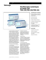
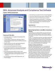
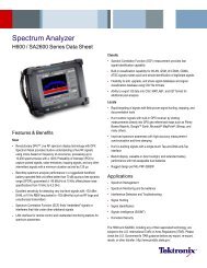
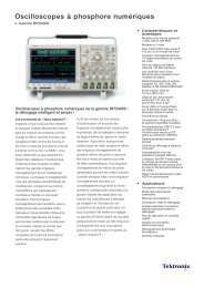
<strong>MIPI</strong> ® M-<strong>PHY</strong> <strong>Transmitter</strong> <strong>and</strong> <strong>Receiver</strong> <strong>Test</strong> <strong>Solutions</strong> — M-<strong>PHY</strong> Essentials, M-<strong>PHY</strong>RX Automation, <strong>and</strong> M-<strong>PHY</strong> ProtocolsDecodeOscilloscope-based Decode for M-<strong>PHY</strong> 8b-10b.Oscilloscope-based Decode for M-<strong>PHY</strong> 8b-10bThe SR-810B Serial Analysis application option enables Decode,Search, <strong>and</strong> Trigger on 8b/10b bus events for fast verification. All<strong>Tektronix</strong> MSO/DPO/DSA70000 Series oscilloscopes are equippedwith a dedicated trigger chip for triggering on 8b/10b data patterns inhigh-speed serial signals up to 6.25 Gb/s. Installed as part of TekScopefirmware, this software ensures findingevenrareevents.Furthermore,theDPO/DSA/MSO70000 Series oscilloscopes with PTD software supportseveral 8b10b data values for triggering.A very unique feature of the SR-810B option <strong>and</strong> perhaps the most powerfuldebugging tool is the capability to trigger on 8b/10b code errors. No serialtrigger would be able to trigger on all possible character errors, disparityerrors, or losses of byte synchronization, but the <strong>Tektronix</strong> 8b/10b serialtrigger allows triggering on common errors such as disparity or charactererrors.Oscilloscope-based Decode for M-<strong>PHY</strong> DigRFv4.Oscilloscope-based Decode for M-<strong>PHY</strong>DigRFv4The Moving Pixel M<strong>PHY</strong>VIEW Protocol Decode software automaticallyrecognizes M-<strong>PHY</strong> data speeds, disassembles, decodes the DigRFv4 datastreams, <strong>and</strong> displays the decoded data in different readable-data formats.The software can be configured to acquire up to 4 lanes of data traffic atatime.The M<strong>PHY</strong>VIEW software can be connected to a remote oscilloscope, <strong>and</strong>executed remotely from any Windows system, using TekVISA. The Filter<strong>and</strong> Search tabs enable searching <strong>and</strong> possibly highlighting records thatsatisfy given criteria. The M<strong>PHY</strong>VIEW also supports bit-sync, align, 10b-8bdecode form packets, <strong>and</strong> disassemble.Required Equipment for <strong>MIPI</strong> ® (M-<strong>PHY</strong> <strong>and</strong>D-<strong>PHY</strong>) <strong>Transmitter</strong> <strong>and</strong> <strong>Receiver</strong> <strong>Test</strong>ingFor a complete list of required equipment please visithttp://www.tek.com/<strong>MIPI</strong>.www.tektronix.com 5
Data SheetCharacteristicsM-<strong>PHY</strong>RX CharacteristicsCharacteristicSpecificationProbing ConfigurationReportsMeasurementsDescriptionM-<strong>PHY</strong> Essentials CharacteristicsCharacteristicM-<strong>PHY</strong> BaseSpecificationM-<strong>PHY</strong> Conformance<strong>Test</strong> SpecificationProbing ConfigurationReportsM-<strong>PHY</strong> Base Specification Revision 1.0, <strong>and</strong>Conformance <strong>Test</strong> SpecificationDifferential acquisition using differential probes or SMAcables.MHT format <strong>and</strong> Excel .XLS format, with Pass/FailtablesHigh-speed mode<strong>Test</strong> 2.1.1 – Differential Input Voltage AmplitudeTolerance(V DIF-RX )<strong>Test</strong> 2.1.2 – <strong>Receiver</strong> Eye Opening <strong>and</strong> AccumulatedDifferential Input Voltage (T EYE-RX ,V DIF-ACC-RX )<strong>Test</strong> 2.1.3 – Common Mode Input Voltage Tolerance(V CM-RX )<strong>Test</strong> 2.1.4 – HS-RX Differential Termination EnableTime (T TERM-ON-HS-RX )<strong>Test</strong> 2.1.5 – HS-RX Differential Termination DisableTime (T TERM-OFF-HS-RX )<strong>Test</strong> 2.1.7 – <strong>Receiver</strong> Jitter Tolerance (TJ RX ,SJ RX ,RJ RX ,STTJ RX ,STSJ RX )<strong>Test</strong> 2.1.8 – <strong>Receiver</strong> Pulse Width Tolerance (T PULSE-RX )DescriptionRevision 1.0Revision 0.65Single-ended acquisition using single-ended probes, ordifferential probes in a single-ended fashionMHT format, with Pass/Fail tables <strong>and</strong> waveformscreenshotsThe following tables provide the details of transmitter test coverage for both the basespecification as well as conformance test specification.Tx Measurements (Base Specification)<strong>Test</strong> Name <strong>and</strong>GroupDifferential Peak toPeak Voltage<strong>Test</strong> Symbol HS-LargeSwing HS-SmallSwingV DIF_PK_L_NT_TX Yes YesV DIF_PK_L_RT_TX Yes YesV DIF_PK_S_NT_TX Yes YesV DIF_PK_S_RT_TX Yes YesV CM_S_TX Yes YesCommon ModeVoltage V CM_L_TX Yes YesSlew Rate inFastest Slew RateStateSR DIF_TX Yes Yes<strong>Transmitter</strong> Pulse T PULSE_TX Yes YesWidthEye Opening T EYE_TX Yes YesDeterministic Jitter DJ TX Yes YesTotal Jitter TJ TX Yes YesTotal Jitter for Short TJ TX Yes YesLaneShort Term Jitter STJ TX Yes YesResolution of Slew ΔSR DIF_TX Yes YesRate StatesPower SpectralDensity/MagnitudePSD Yes YesTx Measurements (Conformance Specification)<strong>Test</strong> 1.1.1 – HS-TX Differential DC Output Voltage Amplitude (V DIF-DC-xA-xT-TX )<strong>Test</strong> 1.1.2 – HS-TX <strong>Transmitter</strong> Eye Opening (T EYE-TX )<strong>Test</strong> 1.1.3 – HS-TX Maximum Differential AC Output Voltage Amplitude(V DIF-AC-xA-xT-TX )<strong>Test</strong> 1.1.4 – HS-TX Common Mode Output Voltage Amplitude (V CM-xA-TX )<strong>Test</strong> 1.1.5 – HS-TX 20/80% Rise <strong>and</strong> Fall Times (T R-HS-TX <strong>and</strong> T F-HS-TX )<strong>Test</strong> 1.1.7 – HS-TX Slew Rate (SR DIF-TX )<strong>Test</strong> 1.1.10 – HS-TX Intra-lane Output Skew (T INTRA-SKEW-TX )<strong>Test</strong> 1.1.11 – HS-TX <strong>Transmitter</strong> Pulse Width (T PULSE-TX )<strong>Test</strong> 1.1.12 – HS-TX Total Jitter (TJ TX )<strong>Test</strong> 1.1.13 – HS-TX Deterministic Jitter (DJ TX )<strong>Test</strong> 1.1.14 – HS-TX Short-term Total Jitter (STTJ TX )<strong>Test</strong> 1.1.15 – HS-TX Short-term Deterministic Jitter (STDJ TX )<strong>Test</strong> 1.1.16 – HS-TX Common Mode Power Spectral Magnitude Limit (PSD CM-TX )Ordering InformationM-<strong>PHY</strong>RX AutomatedModelDescriptionDPO/DSA/MSO70000C DPO (Digital Phosphor Oscilloscope), DSA (DigitalSerial Analyzer), or MSO (Mixed Signal Oscilloscope)Oscilloscopes –6 GHz <strong>and</strong> above is recommended for HS-Gear18 GHz <strong>and</strong> above is recommended for up to HS-Gear220 GHz <strong>and</strong> above is recommended for up to HS-Gear3AWG7000C Arbitrary Waveform Generator –DPO/DSA/MSO70000COpt. M-<strong>PHY</strong>RX* 2DPO-UPOpt. M-<strong>PHY</strong>RX* 2DPOFL-M-<strong>PHY</strong>RX* 2AWG7082C or AWG7102* 3 or above is recommendedfor HS-Gear1AWG7122B/C without Interleave Option 06 isrecommended for up to HS-Gear2AWG7122B/C with Interleave Option 06 isrecommended for up to HS-Gear3M-<strong>PHY</strong> Automated <strong>Receiver</strong> SolutionIncludes: Latest TekExpress product software DVDkit (P/N 020-2913-xx) <strong>and</strong> upgrade SW key. Onlinedocumentation <strong>and</strong> printable manual in PDF format aresuppliedM-<strong>PHY</strong> Automated <strong>Receiver</strong> Solution – FloatingLicense* 2 Requires Frame <strong>and</strong> Bit Error Rate Detector for High-speed Serial St<strong>and</strong>ards (Option ERRDT <strong>and</strong> ST6G).* 3 LAN interface is not supported.M-<strong>PHY</strong> EssentialsModelDescriptionDPO/DSA/MSO70000C/D DPO (Digital Phosphor Oscilloscope), DSA (DigitalSerial Analyzer), or MSO (Mixed Signal Oscilloscope)Oscilloscopes –6 GHz <strong>and</strong> above is recommended for HS-Gear18 GHz <strong>and</strong> above is recommended for up to HS-Gear220 GHz <strong>and</strong> above is recommended for up to HS-Gear3DPO/DSA/MSO70000C/D <strong>MIPI</strong> ® M-<strong>PHY</strong> <strong>Transmitter</strong> Debug, Characterization, <strong>and</strong>Opt. M-<strong>PHY</strong>* 4Conformance <strong>Test</strong> SolutionDPO/MSO70000CGSAOpt. M-<strong>PHY</strong>* 4DPO-UP/DPO7UPOpt. M-<strong>PHY</strong>* 4DPOFL-M-<strong>PHY</strong>* 4 <strong>MIPI</strong> ® M-<strong>PHY</strong> <strong>Transmitter</strong> Debug, Characterization, <strong>and</strong>Conformance <strong>Test</strong> Solution (Floating License version)* 4 Requires DPOJET Jitter <strong>and</strong> Eye Analysis Tools (Opt. DJA).6 www.tektronix.com
<strong>MIPI</strong> ® M-<strong>PHY</strong> <strong>Transmitter</strong> <strong>and</strong> <strong>Receiver</strong> <strong>Test</strong> <strong>Solutions</strong> — M-<strong>PHY</strong> Essentials, M-<strong>PHY</strong>RX Automation, <strong>and</strong> M-<strong>PHY</strong> ProtocolsDecodeM-<strong>PHY</strong> DecodesModelM<strong>PHY</strong>VIEWDPO-UP Opt. SR-810BDescriptionM-<strong>PHY</strong> DigRFv4 CommView Protocol Decode(3rd-party software)8b/10b Serial AnalysisFixtures for M-<strong>PHY</strong> EssentialsM-<strong>PHY</strong> is a chip-to-chip interface. Most M-<strong>PHY</strong> designs are live withhost-device/Master-Slave receiver-ends connected. For these live setups nofixtures or termination boards are required, as termination is taken care of by thereceiver end. For non-live setups, M-<strong>PHY</strong> termination boards are expected to beavailable from University of New Hampshire (UNH-IOL) soon.Recommended Probes for M-<strong>PHY</strong> Essentials <strong>and</strong> M-<strong>PHY</strong>Decodes- 2x P7240 (HS-Gear1), or- 2x P73xx/P73xxSMA (up to HS-Gear2), or- 2x P75xx with P75LRST tip (up to HS-Gear3)Optional Accessories for M-<strong>PHY</strong> <strong>Receiver</strong> <strong>Test</strong>ing- 2x TCA-SMA Connectors, for AWG custom patterns creationOptional Software for M-<strong>PHY</strong> <strong>Receiver</strong> <strong>Test</strong>ing- NI <strong>Test</strong>St<strong>and</strong> Software – For additional automation <strong>and</strong> test sequencecustomization (www.ni.com)- Serial Express Software – For custom patterns using AWG-Option01–Memoryexpansionto64MenabledonAWG- Option 08 – Fast Sequence Switching enabled on AWG- Option 09 – Subsequence <strong>and</strong> Dynamic Jump enabled on AWGPrerequisite Host System Software Requirements forM-<strong>PHY</strong>RX- Microsoft XP OS with SP2 or later, or Windows 7-MicrosoftExcel2002orabove- Microsoft Explorer 6.0 SP1 or later- Adobe Reader 6.0 or equivalent software for viewing Portable Document Format(PDF) files- 2x P73xx/P73xxSMA for PWM All GearsRecommended Probes <strong>and</strong> Accessories for M-<strong>PHY</strong>RXAutomated- 1x P73xxSMA Differential Probe- 2x Matched pair of SMA cables-1xGPIBCable- 2x Rise Time Filter – 120 ps (part number 5915-121-120PS from Picosecond)with barrel connectors- 2x BiasTee, for AWG Interleave Optionwww.tektronix.com 7
Data SheetContact <strong>Tektronix</strong>:ASEAN / Australasia (65) 6356 3900Austria 00800 2255 4835*Balkans, Israel, South Africa <strong>and</strong> other ISE Countries +41 52 675 3777Belgium 00800 2255 4835*Brazil +55(11)37597627Canada 1 800 833 9200Central East Europe <strong>and</strong> the Baltics +41526753777Central Europe & Greece +41 52 675 3777Denmark +4580881401Finl<strong>and</strong> +4152675 3777France 00800 2255 4835*Germany 00800 2255 4835*Hong Kong 400 820 5835India 000 800 650 1835Italy 00800 2255 4835*Japan 81 (3) 6714 3010Luxembourg +41526753777Mexico, Central/South America & Caribbean 52 (55) 56 04 50 90Middle East, Asia, <strong>and</strong> North Africa +41 52 675 3777The Netherl<strong>and</strong>s 00800 2255 4835*Norway 800 16098People’s Republic of China 400 820 5835Pol<strong>and</strong> +41 52 675 3777Portugal 80 08 12370Republic of Korea 001 800 8255 2835Russia & CIS +7 (495) 7484900South Africa +41526753777Spain 00800 2255 4835*Sweden 00800 2255 4835*Switzerl<strong>and</strong> 00800 2255 4835*Taiwan 886 (2) 2722 9622United Kingdom & Irel<strong>and</strong> 00800 2255 4835*USA 1 800 833 9200* European toll-free number. If not accessible, call: +41 52 675 3777Updated 10 February 2011For Further Information. <strong>Tektronix</strong> maintains a comprehensive, constantly exp<strong>and</strong>ingcollection of application notes, technical briefs <strong>and</strong> other resources to help engineers workingon the cutting edge of technology. Please visit www.tektronix.comCopyright © <strong>Tektronix</strong>, Inc. All rights reserved. <strong>Tektronix</strong> products are covered by U.S. <strong>and</strong> foreign patents,issued <strong>and</strong> pending. Information in this publication supersedes that in all previously published material.Specification <strong>and</strong> price change privileges reserved. TEKTRONIX <strong>and</strong> TEK are registered trademarks of<strong>Tektronix</strong>, Inc. All other trade names referenced are the service marks, trademarks, or registered trademarksof their respective companies.07 Dec 2011 61W-27714-0www.tektronix.com