MIPI M-PHY Transmitter and Receiver Test Solutions - M ... - Tektronix
MIPI M-PHY Transmitter and Receiver Test Solutions - M ... - Tektronix
MIPI M-PHY Transmitter and Receiver Test Solutions - M ... - Tektronix

You also want an ePaper? Increase the reach of your titles
YUMPU automatically turns print PDFs into web optimized ePapers that Google loves.
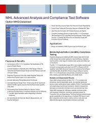
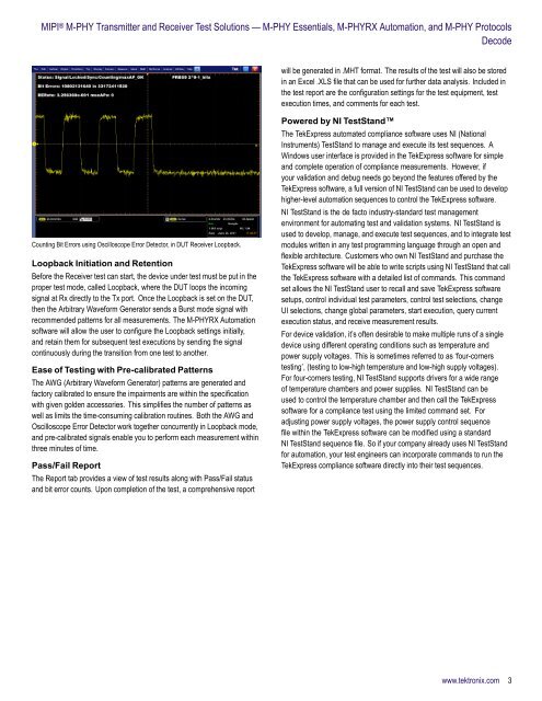
<strong>MIPI</strong> ® M-<strong>PHY</strong> <strong>Transmitter</strong> <strong>and</strong> <strong>Receiver</strong> <strong>Test</strong> <strong>Solutions</strong> — M-<strong>PHY</strong> Essentials, M-<strong>PHY</strong>RX Automation, <strong>and</strong> M-<strong>PHY</strong> ProtocolsDecodewill be generated in .MHT format. The results of the test will also be storedin an Excel .XLS file that can be used for further data analysis. Included inthe test report are the configuration settings for the test equipment, testexecution times, <strong>and</strong> comments for each test.Counting Bit Errors using Oscilloscope Error Detector, in DUT <strong>Receiver</strong> Loopback.Loopback Initiation <strong>and</strong> RetentionBefore the <strong>Receiver</strong> test can start, the device under test must be put in theproper test mode, called Loopback, where the DUT loops the incomingsignal at Rx directly to the Tx port. Once the Loopback is set on the DUT,then the Arbitrary Waveform Generator sends a Burst mode signal withrecommended patterns for all measurements. The M-<strong>PHY</strong>RX Automationsoftware will allow the user to configure the Loopback settings initially,<strong>and</strong> retain them for subsequent test executions by sending the signalcontinuously during the transition from one test to another.Ease of <strong>Test</strong>ing with Pre-calibrated PatternsThe AWG (Arbitrary Waveform Generator) patterns are generated <strong>and</strong>factory calibrated to ensure the impairments are within the specificationwith given golden accessories. This simplifies the number of patterns aswell as limits the time-consuming calibration routines. Both the AWG <strong>and</strong>Oscilloscope Error Detector work together concurrently in Loopback mode,<strong>and</strong> pre-calibrated signals enable you to perform each measurement withinthree minutes of time.Pass/Fail ReportThe Report tab provides a view of test results along with Pass/Fail status<strong>and</strong> bit error counts. Upon completion of the test, a comprehensive reportPowered by NI <strong>Test</strong>St<strong>and</strong>The TekExpress automated compliance software uses NI (NationalInstruments) <strong>Test</strong>St<strong>and</strong> to manage <strong>and</strong> execute its test sequences. AWindows user interface is provided in the TekExpress software for simple<strong>and</strong> complete operation of compliance measurements. However, ifyour validation <strong>and</strong> debug needs go beyond the features offered by theTekExpress software, a full version of NI <strong>Test</strong>St<strong>and</strong> can be used to develophigher-level automation sequences to control the TekExpress software.NI <strong>Test</strong>St<strong>and</strong> is the de facto industry-st<strong>and</strong>ard test managementenvironment for automating test <strong>and</strong> validation systems. NI <strong>Test</strong>St<strong>and</strong> isused to develop, manage, <strong>and</strong> execute test sequences, <strong>and</strong> to integrate testmodules written in any test programming language through an open <strong>and</strong>flexible architecture. Customers who own NI <strong>Test</strong>St<strong>and</strong> <strong>and</strong> purchase theTekExpress software will be able to write scripts using NI <strong>Test</strong>St<strong>and</strong> that callthe TekExpress software with a detailed list of comm<strong>and</strong>s. This comm<strong>and</strong>set allows the NI <strong>Test</strong>St<strong>and</strong> user to recall <strong>and</strong> save TekExpress softwaresetups, control individual test parameters, control test selections, changeUI selections, change global parameters, start execution, query currentexecution status, <strong>and</strong> receive measurement results.For device validation, it’s often desirable to make multiple runs of a singledevice using different operating conditions such as temperature <strong>and</strong>power supply voltages. This is sometimes referred to as ‘four-cornerstesting’, (testing to low-high temperature <strong>and</strong> low-high supply voltages).For four-corners testing, NI <strong>Test</strong>St<strong>and</strong> supports drivers for a wide rangeof temperature chambers <strong>and</strong> power supplies. NI <strong>Test</strong>St<strong>and</strong> can beused to control the temperature chamber <strong>and</strong> then call the TekExpresssoftware for a compliance test using the limited comm<strong>and</strong> set. Foradjusting power supply voltages, the power supply control sequencefile within the TekExpress software can be modified using a st<strong>and</strong>ardNI <strong>Test</strong>St<strong>and</strong> sequence file. So if your company already uses NI <strong>Test</strong>St<strong>and</strong>for automation, your test engineers can incorporate comm<strong>and</strong>s to run theTekExpress compliance software directly into their test sequences.www.tektronix.com 3