DGN 10 - Klay Instruments
DGN 10 - Klay Instruments
DGN 10 - Klay Instruments
- No tags were found...
You also want an ePaper? Increase the reach of your titles
YUMPU automatically turns print PDFs into web optimized ePapers that Google loves.
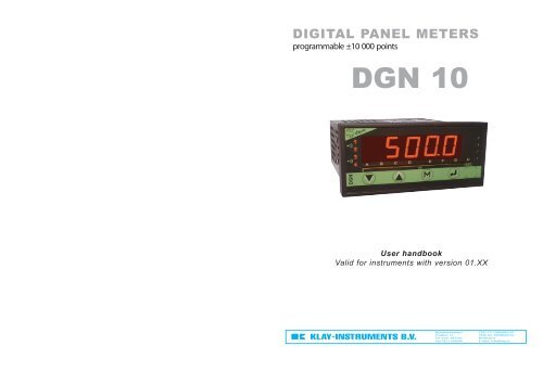
DIGITAL PANEL METERSprogrammable ±<strong>10</strong> 000 points<strong>DGN</strong> <strong>10</strong>User handbookValid for instruments with version 01.XXNijverheidsweg 5Postbus 13Tel. 0521-591550Fax 0521-5920467991 CZ DWINGELOO7990 AA DWINGELOONederlandE-mail: info@klay.nl
1 . INTRODUCTION p22 . SPACE REQUIREMENTS p33 . CONNECTINGS p44 . PROGRAMMING p54.1 Communication with the instrument p54.2 Orientation through the programming p54.3 Main menu p54.4 Programming menu p64.4.1 - Programming of the input p6a / Process signalsp6b / Temperature signalsp7c / Resistive sensorsp74.4.2 - Programming of the display factor p84.4.3 - Programming of the analog output p84.4.4 - Programming of the relay outputs p94.4.5 - Programming of the safeties p94.4.6 - Programming of the display p<strong>10</strong>4.5 Features of the inputs and programming limits p<strong>10</strong>4.5.1 - Current and voltage input p<strong>10</strong>4.6 Features of the outputs and programming limits p114.6.1 - Analog output p114.6.2 - Relay outputs p124.6.3 - Safeties p134.6.4 - Display features p144.7 Reading of the configuration p144.8 Access code p154.9 Programming of a new access code p154.<strong>10</strong> - Functions which can be accessed in the main menu p154.<strong>10</strong>.1 - Display simulation p154.<strong>10</strong>.2 - Simulation of the analog output p164.<strong>10</strong>.3 - Menu CLEAr :Deleting of the recorded alarmsp164.<strong>10</strong>.4 - Menu CLr.tA:Suppressing of the programmed tare p165 . FUNCTIONS WHICH CAN BE REACHED FROMTHE FRONT FACEp175.1 Functions which require pressing only 1 key p17a / Display of the min. valuep17b / Display of the max. valuep17c / Deleting of the min. and max. valuesp175.2 Functions which require pressing several keys p175.2.1 - Display shifting p175.2.2 - Visualisation of the direct measure p185.2.3 - Visualisation and setting of the alarm setpoints p185.2.4 - Setting of the tare (processs input only) p186 . ERROR MESSAGES p197 . GENERAL WARRANTY TERMS p198 . LEXIQUE p19p1
1. INTRODUCTION Features of the inputsThe <strong>DGN</strong> <strong>10</strong> is a high accuracy digital panel meter. It is equipped onfront face with a four 14 mm high red digits display, whose brightnesssuits applications in industrial control rooms perfectly.It allows the display, the control and the transmission of data from anymeasurable magnitudes.AVAILABLE OPTIONS: (specify on order)Insulated analog output: AActive current output, or voltage.Programmable scale ratio with enlarging effect.Relay output:R2 relays: mode setpoint or window.Recording of the alarms.Time delay and hysteresis adjustable on each setpoint.Alarm messages.CODING:• Type: <strong>DGN</strong> <strong>10</strong>• Output options:A : Analog (A1 or A3: specify)R : 2 relaysThese options can be combined simultaneously.Order example:For a digital panel meter with 1 active current analog output and 2relays, request reference <strong>DGN</strong> <strong>10</strong> A1R.Types ofINPUTSMeasure range adjustablefrom:PermanentoverloadmA♣ -2 to +22mA ±<strong>10</strong>0mAmV♠♣ -<strong>10</strong> to +1<strong>10</strong>mV ±1VV♣Thermocouples ♠Standard IEC 581JKBRSTENLWW3WRE5°C-160/1200-270/1370200/1820-50/1770-50/1770-270/4<strong>10</strong>-120/<strong>10</strong>000/1300-150/9<strong>10</strong><strong>10</strong>00/23000/24800/2300-0.1 to +1.1 V-1 to +11V±50V-30 to +330V ±600V°F-256/2192-454/2498392/3308-58/3218-58/3218-454/770-184/1832-32/2372-238/16701832/417232/449632/4172 -Intrinsicerror
Features of the outputs2. SPACE REQUIREMENTSCodeTypes ofOUTPUTSFeaturesCase dimensions: (with terminals)96 x 48 x 124 mmA1A31 insulated analogoutputactivecurrentor voltageCurrent: direct or reversed 0-20mALoad impedance ≤ Lr 600ΩVoltage: direct or reversed 0-<strong>10</strong>VLoad impedance ≥ Lr 500kΩMounting panelmax. thickness: 30terminalsR2 inverting relays2 setpoints per relayconfigurable on the whole MR.Hysteresis programmable from 0 to <strong>10</strong>0%.Time delay programmable from 0 to 25 sec.(8A/250 VAC on resistive load)casetighteningsexternalsealGeneral featuresGalvanic partition:2.5 kV eff. - 50 Hz - 1 min between supply, inputs, outputsPanel mountingcut out 44 x 91 mmPower supply:Max. operating rangePower draw20 to 270 VAC - 50/60/400 Hz and20 to 300 VDC• Standard sampling time: <strong>10</strong>0 ms• Common mode rejection rate: 130 dBSerial mode rejection rate: 40 dB 50/60 Hz3 W max.5.5 VA max.• Zero drift compensation and self-calibration• Conform with standards IEC 6<strong>10</strong>00-6-4 on rejections and IEC 6<strong>10</strong>00-6-2 immunity(in industrial environment) IEC 6<strong>10</strong>00-4-2 level 3, IEC 6<strong>10</strong>00-4-3 level 3,IEC 6<strong>10</strong>00-4-4 level 4, IEC 6<strong>10</strong>00-4-6 level 3.CE marking according to the directive EMC 89-336.Protection :Front face: IP 65Housing: IP20Terminals: IP 20Housing:Self-extinguishing case ofblack UL 94 V0 ABS.Plug off connectors on rear face forscrewed connectings (2.5mm², flexibleor rigid)Display: ±<strong>10</strong> 000 points (14 mm)Electroluminescent red (green optional)2 alarm ledsp3
440Ω up to 2kΩ(0-8kΩ optional)Strap 4 and 7 on terminalPotentiometerA161514131211T2C2R2T1C1R1AT: ONC: CommonR: OFFVOUT GND VCC3-wiretransmitterOUTPUTS (options)VOLTAGECURRENTAPOWER SUPPLYACDC1 2~ ~+ -A<strong>10</strong>90-<strong>10</strong>V+ -V<strong>10</strong>90-4/20mA+ -mAp4
4. PROGRAMMING4.1 Communication with the instrumentSeveral functions can be accessed directly on front face:AlarmsLed 1Led 2Display ofthe min.value p17Display ofthe max.value p17Display of themeasureMAccess to themain menu p50 reset of themin. and max.p17Further functions can be accessed by pressing several keys simultaneously:4.2 Orientation through the programmingThe dialogue is ensured by 4 keys located on the front face.Move through the menus:downwards, or decreasethe value shownMValidation of the displayedparameter, or access to a submenuNote: In mode programming, the istrument will automatically revert tothe measure with the former configuration if no key is pressed during1min.MExit from a submenu to accessnext menu / access to the programmingexit menuMove through the menus:upwards, or increase thevalue shown++++MMSetting of the display down scale; (see p17)Setting of the display full scale; (see p17)Visualisation of the direct measure (voir p18)M Visualisation and setting of the alarm setpoints; (see p18)rEAd«ProG«P.CodE«(relay/analogoutputs)SIMUL«(analogoutput)GEnE.«(relay output)CLEAr«(inputs process,resis., potent.)CLr.tA«Reading convention:«Move through the main menuRevert to previous menuBlinking display: awaiting validation or settingAlternating information displayEntering of a parameter:6888658865286520First start by increasing or decreasingthe 1st digit and the sign: from -9 to +9.the 2nd from 0 to 9.the 3rd from 0 to 9.the 4th from 0 to 9.Between each entering, validatethe cipher with keyandMode readingof theconfiguration(see p14)CodE8 888«If code correct,access to theprogrammingmenu(see p6)Programmingof the accesscode(see p15)If codeincorrect,messageappearsnoSimulation ofthe display(see p15)Authorized byaccess codeSimulationof the analogoutput(see p16)Authorized byaccess codeDeleting ofthe recordedalarms(see p16)Entering of the access codeThe access to the programmingmenu is protected by a 4-ciphercode.On factory exit, the code is 0000(to change the code, see page15).0 reset ofthe functionTARE(see p16)Authorized byaccess codep5
4.4 Programming menu (according to options)InPutdiSPL.AnA.rELAYSECUPr.diSSAvEAccess to the programming of the inputAccess to the programming of the display factorAccess to the programming of the analog output(option analog output)Access to the programming of the relays(option sortie relay output)Access to the programming of the outputs, the relays p9in case of error self-diagnosis and/or sensorrupture, and access to disconnecting the sensor rupture(option analog or relay output)Access to the programming of the displayAccess to the programming exit menu withor without saving of the configurationp6p8p8p9p<strong>10</strong>p<strong>10</strong>4.4.1 Programming of the inputInPuttyPECALiba. Process signals«voltage inputchoice of the caliber«diSPL.U<strong>10</strong>0M«1U«<strong>10</strong>Uvoltage input only«MAcurrent input300U««2.UirEyES noInPutto t° sensorsresistive sensorsConnection of the mAsensor:Choose YES if amA passive sensoris to be connectedbetween terminals 5and 8 (2-wiretransmitters)Note:⇒ In mode programming, the instrument will automatically revert to measurewith the former configuration if no key is pressed during 1min.Note:PressMto go on to next menuMove through the menus / choiceMMenu exit / accessDownwards move /decreaseUpwards move / increaseValidation / vertical movep6
. Temperature signalsprocesssignalsInPutc. Resistive sensorstemperature signalsprocess signalsInPuttEMP«temperature inputsrES«Pot«If other than thermocoupleCAPt.t otc--CJCCJ-t °AdJuS.««««If thermocoupleCJC *externalexternal CJC only««yESPt <strong>10</strong>0o C««««#compensationCJC-Enoo F«««««# Changing this parameter requires re-programmingthe following parameters related to the relays and theanalog output:SPxx, hystx, do.diS, Fo.diS«tc-J tc-CA tc-S tc-r tc-t tc-E«tc-b tc-n tc-C tc-C3 tc-C5 tc-L(2)«-888.8ni <strong>10</strong>0««CJC-itc««(2)internalIf no shifting««««-<strong>10</strong>°.0C < CJC < 60°.0C14°.0F < CJC < 140°F««dISPSee also the features of the inputs p<strong>10</strong>Note:PressMCALibM«400«or2000to go on to next menuMenu exit / accessDownwards move /decrease«or8000«Upwards move /increaseif resistanceaccording to optionMove through the menus / choiceValidation / vertical moveAvailable only in the case where ashifting of the input has been entered(see page 17)diSPL.Note:PressMto go to menudiSPL.Move through the menus / choice* cold junction compensation,except thermocoupleB which isonly in CSF-E (externalCJC)p7
4.4.2 Programming of the display factorDISP«PointFunct.nbA00A19b00b19Cut.oFIntEG.«««««««««(1)(1)inputs process, resistance, potentiometer--.--Li.SPE0020-88.88-88.88-88.88-88.88nointegration indice0000«««place of the decimal pointfunction speciallinearisation««««««From 3 to 20 : represents thenumber of points (includingthe down and full input scale)Xoo=dinpXNB-1=F.INPsetting in display points (or in inputpoints if SCALE NO is programmed)of the same number of ordinates“bxx” and abscisses “Axx”if SCALE YES :Y00 = dDIS and YNB-1 = F.DISyES-88.88««LinEA.«setting in display pointslinear functiond.inF.ind.diSPF.diSPIntEG: coefficient from 0 toAnA. or rELAy orSECU(1)(1)rESOL.diSPL.«display resolution1 or 1/<strong>10</strong>th of degree««««down scale-88.88full scale-88.88-88.88-88.88temperature input0.1 o«««««in mV, V or mAaccording to thetypein mV, V or mAaccording to thetypedisplay correspondingto theinput down scale«dInp»display correspondingto theinput full scale«F.INP»according to options1 o-2< x < 22.00 (mA)(1)-1< x
ELAYidemREL1PAr14.4.4 Programming of the relay outputs (if option) 4.4.5 Programming of the safetiesrEL.1rEL2InPUt diSPL««alarmAL.1ModE.1SP 1SP1.1SP2.1HySt.ItiME.1LEd1MEM.1MESSI««««««««««See also thefeatures of therelay outputsp12(5)activeOn02.0002.0004.0000.00000.0«mode setpointaccess to SP1if mode setpoint programmedif mode window programmed«SP2.1 must be ≥ SP1.1«hysteresis«0 < hys. < 9999in display pointstime delay on the relayOFFnono««««de-activated0 < tIME < 025.0in 0.1s incrementsOnYESyESABCD««««mode windowaccess to SP1.1rELAYchoice of the status of the relayassociated ledON : led lit when relay activeOFF : led still when relay activefunction recording of the alarmsfunction display of an alarm messageenter 4 charactersat the end of menu rEL.2,rEL.2 access to SECU or Pr.diS«OFF«(5) choice of the relayoperating mode:mode setpoint orwindow(see page 12)SECU«rUPt.dIAG.««CAPt.rEL.1rEL.2OUt.IrEPLirEL.1rEL.2OUt.IrEPLiIf input mV, temperature, resistanceor mA (if dINP and F.INP > 3.5mA)disconnection of the sensor rupt.«««««««««OnOFF«OUt.ULO«if input mV or t°status of the relay 1 in case of sensor ruptureOFForor««LO«HIstatus of the relay 2 in caseof sensor ruptureyES««OFF«HIif return value programmedvalue of the output in case of sensor rupture00.00
4.4.6 Programming of the brightness, of the displayPr.diSExit from the programming with or without savingrevert to measuredisplaySAvEyESexit andsave theconfigurationnoexit withoutconfigurationsavingSAvEPrDIbr.diGL.dIGnuLL««setting of the brighness of the displays1 1 1 1not enforced to 0««on 4 levelsstatus of the last digit (right hand side)yES no«On OFFdeleting of the unsignificant zeros««enforced to 0Note: An exit fom mode programming with saving of the configuration(SAVE, YES) will automatically reset to zero the tare, the min. and the max.as well as the alarm recordings.4.5 Features of the inputs and programming limits4.5.1 Current inputSpecial linearisation:MALi.SPE«For specific applications such as the measurement of volume, themeter can memorise an unlinear curve, programmable in X and in Y.«and voltageUThe curve resulting from your equation can be replaced by a series oflinear segments, with a maximum of 20 points (19 segments).SAvE«Note: The values of the abscisses (x) must go increasing d.in < value ofA01 < value of A02...< F.in.Example :For a layed cylindric tank, 1 meter high (h) and 1 meter long (l); a 0-20mA linear sensor measures the height of the liquid surface line:Input of the meter: height h0 meter -> 0 mA (empty tank)1 meter -> 20 mA (full tank)with cos β/2 = ( R - h ) / RSin β/2 = C/2RR (ray)(R)βh(height)L (length)C (chord)p<strong>10</strong>
Display of the meter:Empty tank volume d.diSP = 0.000Full tank volume F.diSP =0.785Volume = L [π R² β/360 - C(R-h)/2]Say a curve of <strong>10</strong> equally long segments:Measure range / number of segments = 20mA/<strong>10</strong> = 2mA length ofthe segment. For <strong>10</strong> segments nb = 9 (11 points to be programmed,including d.in and F.in).Input mAd.in 0A01 2A02 4A03 6A04 8A05 <strong>10</strong>A06 12A07 14A08 16A09 18F.in 20Heightm0.00.<strong>10</strong>.20.30.40.50.60.70.80.91.0Degree0.0073.74<strong>10</strong>6.26132.84156.93180.00203.07227.16253.74286.76360.00Chordm0.000.600.800.920.981.000.980.920.700.600.00d.diSPB01B02B03B04B05B06B07B08B09F.diSPVolumem 30.0000.04<strong>10</strong>.1120.1980.2930.3930.4920.5870.6740.7450.785Outputsin mA00.0001.0402.8505.0407.47<strong>10</strong>.0012.5414.9617.1718.9820.00Programming:d.in = 0 mA F.in = 20 mAnb = 9d.disp = 0,000 m 3 F.disp = 0,785 m 3Programming from A01 to A09 and from B01 to B09 according to thetable.volume output (mA)in m 3 Y0.79200.75180.67160.59140.49120.39 <strong>10</strong>80.2960.200.140.04 24.6 Features of the outputs and programming limits4.6.1 Analog outputOut.iOut.U0/4-20mA active current output, or 0-<strong>10</strong>V voltage output• Accuracy: 0.1 % in relation to the display (at +25°C)• Residual ripple ≤ 0,2%• Admissible load 0Ω ≤Lr ≤ 600Ω (current)Lr ≥ 500 kΩ (voltage)• Scale ratio programmable with enlarging effect• Response time: 40 ms in relation to the displayd.outF.outdO.diSFO.diS0 2 4 6 8 <strong>10</strong> 12 14 16 18 200 0.1 0.2 0.3 0.4 0.5 0.6 0.7 0.8 0.9 1Down scale of the analog output (eg. 04.00 (4mA))Full scale of the analog output (eg. 20.00 (20mA))Display value corresponding to the output down scaleDisplay value corresponding to the output full scaleIn mode measurement, the analog output can not overstepp <strong>10</strong>% of thegreatest of the 2 values : d.out and F.outorXinput (mA)height (m)p11
4.6.2 Relay outputs :2 relay outputsrEL.1rEL.2• Mode setpointlit led• Hysteresis independently programmable in the display unit.• Time delay independently programmable from 0 to 25 s, in 0.1s increments.• NO-NC contact 8 A - 250 V on resistive loadstill ledSP.X- HYSxSP.XActivation or de-activation of alarm xOnOFFThe status of relay x depends on the performed programmingThe relay X remains stillAL.X• Mode windowlit ledChoice of the operating mode:• Mode setpointOFFONsetpointorONsetpointOFFModE.xSPXSPXChoice of the setting unit of the setpoints and hysteresissetpoints and hysteresis in input scale pointssetpoints and hysteresis in display pointsInPutdiSPL.• Mode windowON ON ONOFF OFFsetpoints or setpt OFF setptSP1.X SP2.XSP1.X SP2.XChoice of the status of the relay associated ledThe led indicates the alarm status.OnOFFLed lit when relay active (coil supplied)Led still when relay active (coil supplied)Legend:ON coil suppliedOFF coil not suppliedPArA.LEdxSetting of the hysteresis in display pointsHySt.x The hysteresis is active on switching from lit led to still led; that is tosay on switching out of alarm, as the led represents the alarm status.still ledSP1.X-HYSt.xSP1.XSP2.X SP2.X+HYSt.xstill led• Time delay on the alarm tiME.xThe relay time delay can be adjusted from 000.0 to 025.0s, in 0.1sincrements. It is active both on switching and switching back.MEM.x• Recording of the alarmsAllows recording the alarm after a setpoint has been passed. When themeasure reverts below the alarm setpoint, the relay remains on and theled blinks to warn the user that a setpoint has been passed (to reset thealarm recordings to 0 see menu CLEAr ).Note: An exit from mode programming with saving of the configurationwill reset the alarm recordings to zero.MESSx• Display of the alarm messagesA programmed alarm message can be made to appear alternating withthe measure. The message will appear only during the alarm, while theassociated led is lit.• Setting of the setpoints: there are 2 ways to adjust setpoints:- either in mode programming entering the correct access code,- or by pressing simultaneously on and if the access to a quickentering has been authorized on the programming of the code (see p18).Mp12
4.6.3 Safeties:• Self-diagnosis:The meter permanently watches any drifts which may occur on its components.The self-diagnosis serves to warn the user in case of abnormalincrease of these drifts before they may provoque false measures.The information of self-diagnosis error can be reported:· On the display: An error message appears alternating with themeasure; an error code is registered and can be read in themenu AboutCoding:1 : Programming error2 : Offset error4 : Input calibration error8 : Output calibration error64: Upper or lower electrical overstepping of the inputIf the instrument detects for instance an offset error (2) and a programmingerror (1) the value of the error code will be 3 (2+1).· On the relays:No influence on the relay in case of self-diagnosis errorOFFLOHIdiAGRelay de-activated (coil not supplied) in case of selfdiagnosiserrorRelay active (coil supplied) in case of self-diagnosis errorNote : The led is either still or lit according to its programming in the menurELAY.· On the analog outputIf a return value has been enteredValue between: 0 and 22 mA (current output)or 0 and 11 V (voltage output)· On the converter: the led ON blinks fastThe information of sensor rupture can be reported:· On the relaysOFF No influence on the relay in case of sensor ruptureRelay de-activated (coil not supplied) in case of sensorLO ruptureRelay active (coil supplied) in case of sensor ruptureHINote: the led is either still or lit according to its programming in the menurELAY.· On the analog outputIf a return value has been enteredValue between: 0 and 22 mA (current output)or 0 and 11 V (voltage output)· On the display: MessageNote: The sensor rupture detection has a priority over the selfdiagnosis.· On the converter: the led ON blinks slowly• Disconnection of the sensor rupture(If input mV or temperature)The sensor rupture detection can be disconnected in order not to disturbsome calibrators which may be sensitive to the detection current.In the menu :CAPt.OnOFFSECUValidation (or not) of the sensor rupture detectionDetection activeDetection inactiveOPENruPt.• Sensor ruptureThe sensor rupture can be detected on inputs mV, Tc, Pt<strong>10</strong>0, Ni<strong>10</strong>0,resistance, and current if the down and full scale > 3.5 mA.p13
4.6.4 Display features:PointrESOL.d.diSPF.diSPCut.oFPlace of the decimal point for the inputs other than temperatureinputsDisplay resolution for the temperature inputs: 0.1° or 1°Display corresponding to the input down scale(except the temperature input)Display corresponding to the input down scale(except for the temperature input)Only for the inputs process, resistance, potentiometer,expressed in display points.− If the display full scale > display down scale and if the display is ≤ tothe cut off value, then it will be held at down scale.− If the display full scale < display down scale and if the display is ≥ tothe cut off value, then it will be held at down scale.• Inhibition of the last digit (bottom weight)In the mode programming, the menu L.dIG allows suppressing the displayof the last digit, the latter being enforced to 0 if OFF is validated.• Deleting of the unsignificant zerosSuppresses the display of the unsignificant zerosnuLL = YES on the left hand side.Eg.: Display value 0015nuLL = no Display = 0015= Display = 15Eg.: Display value 00.15nuLL==YESnoYESDisplay = 00.15Display = 0.15nuLLL.dIG• Response time:intEGIntegration indice of the digital filtering:Programmable from 0 to <strong>10</strong>; for use in case of unsteady input signal.4.7 Reading of the configurationrEAdValidation / verticalmoverEAdintEG 0 1 2Typical responsetime at 90%120 ms 400 ms 600 msTo obtain the maximum response time, add 240 ms.Note: For the response time of the analog output, add 40ms to thevalues shown in the table.For the relays : add the time delay programmed on the alarms.br.diG1 1 1 1 4444• Setting of the digits brightnessLowest brightness31 s6 7 83 s 5 s 7.5 s41.4 s9<strong>10</strong> sStrongest brightness52 s<strong>10</strong>15 sInPutdiSPLAnA.rELAYSECUPr.diSAboutReading of the input parametersReading of the measure display parametersReading of the analog output parameters(if option analog output)Reading of the alarm parameters(if option relay outputs)Reading of the safety parameters for sensorrupture or self-diganosis of the outputsReading of the display programmingparametersReading of the instrument internal parametersIn each reading submenu, use keys and to move, and keyto visualise the parameters.If no key is pressed during 20 s., the instrument will revert to themeasure display.p14
SubmenuAboutValidation /vertical move4.9 Programming of a new access codeXXXXX1 2 3 4 5.X1 : - : No analog outputA : Analog outputX2 X3 : - - : No relay outputr- : Output 2 relaysdGN<strong>10</strong>n °A0123ProG07.000Pt<strong>10</strong>.Ar---.type of the instrumentnumber of the instrumentversion of the programmeXXXXX1 2 3 4 5.code of the installedoptionsP.CodEOLdif code correct(old)Enter previouscodeNEUEnter the newcodeNew code registered, and revert tothe measure displaynoif code not valid(old)display during 2s.and revert to themeasure displayReminder: If no key is pressed during 1 min, the instrument will revert tothe measure display. On factory exit, the access code is 0000.4.8 Access codeAn access code adjustable from 0000 to 9999 serves to protect themeter and its setpoints from unauthorized programming, and to lock theaccess to some functions.0 0 0 0 Factory codex x x x0 to 5 Access to the display shifting6 to 9 No access0 to 5 Access to the display and output simulations6 to 9 No access0 to 5 Access to the function “tare” (except temperature inputs)6 to 9 No accessErr.0000CH.SUMFC4Eerror code in case ofself-diagnosis errorcheck sum of the flashmemory4.<strong>10</strong> Functions which can be reached from the mainmenuM4.<strong>10</strong>.1 Simulation of the display(accessible according to the programmed access code and ifoption relay outputs or analog output)The display can be simulated with the meter in order to validate the configurationof the analog output and the relays in the installation.Press Menu torevert to themeasuredisplay.SIMULSIMULValue of thedisplayifEntering of a newdisplay valueNote: The instrument will no longer measure during the simulation. Theanalog output and the relay outputs will react according to the entereddisplay.If alarm messages have been programmed, they may appear during thesimulation.0 to 5 Access to the quick entering of alarm setpoints6 to 9 No accessp15
4.<strong>10</strong>.2 Simulation of the analog output (mode generator)MPress Menu torevert to themeasure display.(accessible according to the programmedaccess code and if option analog output)GEnE.GEnE.Value of theoutputifEnter the valueto be injectedNote: The instrument will carry on measuring during the simulation. Onlythe analog output will no longer react to the measure.CLr.tA4.<strong>10</strong>.4 Menu : Suppressing of the programmed tare(accessible according to the programmed access code)CLr.tAMthe entered tare is notdeletedsuppressing of the enteredtare, and revert tomeasure displayReminder: If no key is pressed during 20 s.,the instrument will revert to the measure display.4.<strong>10</strong>.3 Menu CLEAr : Deleting of the recorded alarmsIf the function recording of alarms has been programmed:the status of the relay will be recorded after the setpoint has been passed.If the setpoint is passed back the other way, the status of the relay doesnot change and the corresponding led starts to blink.To revert to the normal status (led not blinking and relay in the correctstate) use menu CLEAr.CLEArMthe recorded alarms arenot deleteddeleting of the recordedalarms, and revert to themeasure displayReminder: If no key is pressed during 20 s., theinstrument will revert to the measure display.Note: An exit from mode programming with saving of the configurationwill reset the alarm recordings to zero.p16
5. FUNCTIONS WHICH CAN BE REACHED ONTHE FRONT PANEL5.1 Functions which require pressing only 1 key:a / Display of the min. valueDisplay ofthe measureInF.02.00Alternating informationdisplayMinimum valuec / Deleting of the min. and max. valuesMDisplay ofthe measureCLr.Mb/ Display of the max. valueDisplay ofthe measureSUP.08.00deleting of the recorded min. andmax., and revert to the measuredisplayThe instrument will revert to the measure display.Reminder: If no key is pressed during 20 s., theinstrument will revert to the measure display.Alternating informationdisplayMaximum valueNote: An exit from mode programming with saving of theconfiguration will reset the min. and max. values to zero.5.2 Functions which require pressing several keys:5.2.1 Shifting of the display(accessible according to the programmed access code)MShifting of the display down scale (AdJ.Lo)Shifting of the display full scale (AdJ.Hi)After injecting an input signal corresponding to the down (or full) displayscale, press the keys and (or and M ) simultaneously. Themessage AdJ.Lo (AdJ.Hi) will appear alternating with the value, to indicatethat you are in the menu adjustment.By pressing and you can increase or decrease the down (or full)display scale.If you keep pressing during 3s. on key or you can access a quickincreasing or decreasing of the display value.Press to validae the shifting. The message OK will appear during theacknowledgement of the shifting (1s.), and the instrument will revert tomode measure. Once all the shifting are validated, the input thus shiftedwill keep this shifting even after a setting off tension.Press M (or do not press any key during 20 s) to revert to the measuredisplay without modifications.• Case of a process, resistance or potentiometer inputThe instrument will then re-adjust its scale factor and its display factor inorder to obtain the required result on the display.• Case of a temperature inputOn a temperature input; if 1 of the 2 settings is performed: this will correspondto an offset, which means that all the points will be shifted bythe same quantity.On the contrary, if the 2 settings are performed, the slope and the offsetwill be corrected in order to obtain the required result.example :On a Pt<strong>10</strong>0 input for 0°C, the obtained display is -000.3For 500°C the obtained display is 0500.2. To correct this display, shiftthe display down scale by 3 points to obtain 000.0, and the display fullscale by -2 points to obtain 0500.0.p17
note: only for temperature inputs:From the menu rEAd, the performed scale shiftings can be visualised inthe submenu InPut :offsetshiftingOFFSE.000.3slope andoffsetshifting5.2.2 Visualisation of the direct measurePress and M to visualise the signal directly without processing:scale factor, square root, linearisation− in mV, V or mA for process inputs,− in mV for thermocouple inputs,− in Ω for Pt<strong>10</strong>0, Ni<strong>10</strong>0 inputs,− in Ω for resistance inputs,− in percents for potentiometer inputs.d.diSP-000.3AdJ.Lo000.3F.diSP500.2AdJ.Hi-000.2display down scaleshifting of the displaydown scaledisplay full scaleshifting of the displayfull scaleSuppressing of the input shifting:(Case of a temperature input only)The menu AdJuS. in the mode programming of a temperature inputallows suppressing the entered shifting, or not.no : the instrument will revert to the factory settingsYes: the instrument will take the programmed (offset and/or slope)adjustments into account.5.2.3 Visualisation and setting of the alarm setpointsOption 2 or 4 relaysSetting of the setpoints: There are 2 ways to adjust setpoints :- either in mode programming entering the correct safety access code(see p15)- or by pressing simultaneously on andThe meter will then show the message SP.x or SPx.x alternating withthe value of the corresponding setpoint.The values of the various setpoints can be accessed with and .These setpoints can then be modified (if access code < 6000 (see p15))by pressingto revert to the setpoints rea-When the setpoint is adjusted pressding menu.Once all the setpoints are adjusted, simply press and the meterwill revert to mode measure, taking the new values into account.If no key is pressed during 60 s. the meter will revert to the measuredisplay without modification of the value of the setpoints.5.2.4 Setting of the tare (except temperature inputs)(accessible according to the programmed access code)Press and to enforce the display for the signal currently presenton the input as the display down scaled.dISPNote : The tare will not be memorised in case of power supply cut.To suppress the tare, validate the menu in the main menu p16.An exit from mode programming with saving of the configuration willreset the tare to zero.MCLr.tAMp18
6. ERROR MESSAGES2000OPEnErr.17. GENERAL WARRANTY TERMSWARRANTY applying and durationThis appliance is garanteed for a duration of 1 year against any designor manufacturing defects, under normal operating conditions.Processing conditions * : Processing not under warranty will be submitedto the acceptance of a repair estimate. The customer will returnthe products at his charge, and they will be restored to him after processing.Without a written agreement on the repair estimate within 30days, products will not be held.* Complete warranty terms and details available on request.8. LEXIQUEMessages shown by the meter in mode programming and/or inmode readingGeneral accessrEAdProGCodEP.CodESiMULGEnE.CLEAr«Measure in overrangeSensor ruptureValue set out of rangeTo enter the value again,press----O.LEr.xxxAccess to the reading of the parametersAccess to the programming of the input and output parametersCode for access to the programming of the input and outputparametersProgramming of a new access codeAccess to the display simulationAccess to the simulation of the analog outputDeleting of the recorded alarmsUpper or lower electricaloverstepping of the inputDisplayable value overload.Self-diagnosis error(see page 13)InputsInPutTYPETemperature inputAccess to the input programming submenuInput typeUMAtEMPPotrESType of temperature sensorPt<strong>10</strong>0 inputVoltage inputCurrent inputTemperature inputPotentiometer inputResistance inputPotentiometer and resistance inputCALibChoice of the resistance caliber4002 0008000Voltage input and current inputCAPt.Pt<strong>10</strong>0tcCALThermocouple inputType of thermocoupleThermocouple K (see the table page 3)Type of cold junction compensationInternal CJCExternal CJCPotChoice of the voltage caliber<strong>10</strong>U300U<strong>10</strong>0M1U2.UirEtc--tc.CACJCCJC-ICJC-EUMAInput 0 to <strong>10</strong> V (or -<strong>10</strong>/<strong>10</strong>V)Input 0 to 300 V (or -300/300V)rESInput 0 to <strong>10</strong>0 mV (or -<strong>10</strong>0/<strong>10</strong>0mV)Input 0 to 1 V (or -1/+1V)mA input with supply for 2-wire sensortEMPp19
ni <strong>10</strong>0t°°C°FAdJuS.OFFSE.d.diSPAdJ.LoF.diSPAdJ.HiInput NI<strong>10</strong>0Display parametersPr.diSbr.diGSubmenu programming of the display featuresAdjusting of the digits brightness (4 levels)1 1 1 1 Lowest brightness 4444L.dIGONnuLLyESDisplaydiSPL.Funct.Last digit (bottom weight)Strongest brightnessLast digit in service Last digit enforced to 0Deleting of the unsignificant zerosYesCJ-t°Value of the external CJCType of degreeDegree CelciusDegree FahrenheitShifting of the inputOffset shiftingSlope and offset shifting, display down scaleAdjusting of the display down scaleSlope and offset shifting, display full scaleAdjusting of the display full scaleOFFnoNoAccess to the display programming submenuPoint--.--Choice of the place of the decimal point in mode measurePlace of the decimal pointChoice of the processing functionLi.SPECut.oFrESOL.IntEG.Special linearisationnbAxxbxxNumber of linearisation pointsAbscisse of a special linearisation pointOrdinate of a special linearisation pointCut-off programmable or notDisplay resolution for the temperature inputsResolution 1/<strong>10</strong>th of degree0.1°1°Analog outputOut.UOut.iResolution 1 degreeIntegration indiceAccess to the voltage output programming submenuAccess to the current output programming submenuPArA.InPutdiSPL.d.outF.outdO.diSFO.diSOutput range in input scale pointsOutput range in display pointsDown scale of the analog outputFull scale of the analog outputAccess to the display corresponding to the output downscaleAccess to the display corresponding to the output fullscaled.diSPLinEA.d.inF.inF.diSPLinearInput down scaleInput full scaleDisplay down and full scalep20
Relay outputs: x : 1 or 2Access to the submenu programming of the relay outputsrELAYrEL.xAL.xONPArA.InPutdiSPL.ModE.x_ _I - - - - I_ __I - - I_ - I_ _I -SPxSP1.XSP2.XHYSt.xtiME.xLEdxMEM.xMESSxAccess to the programming of the relay xActivation of the relay output 1ActivationDe-activationSetpoint and hysteresis in input scale pointsSetpoint and hysteresis in display pointsOperating mode of the relay xMode setpointsMode windowValue of the setpoint in mode setpointValue of the 1st setpoint in mode windowValue of the 2nd setpoint in mode windowValue of the hysteresis in display pointsTime delay on relay XOFFProgramming of the led associated with the relayOnOFFLed lit when relay active (coil supplied)Led still when relay active (coil supplied)Recording of the alarm XyESRecordingAlarm messageyESMessagenonoNo recordingNo messageSafetiesSECUruPt.CAPt.OFFrEL.XOFFOut.UrEPLidI A G .OUt.UrEPLiAccess to the submenu programming of the safetiesProgramming of the sensor rupture safetyLOH IOut.iValidation (or not) of the sensor ruptureSensor rupt. inactiveOnStatus of relay X in case of sensor ruptureProgramming of the self-diagnosis safetyrEL.XOFFLOH IyESReturn valueOUt.iyESReturn valueSensor rupt. activeNo sensor rupture associated with the relayRelay de-activated in case of sensor rupture(coil not supplied)Relay active in case of sensor rupture (coil supplied)Return value (or not) of the outputin case of sensor rupture errorReturn value requiredNo return valueStatus of relay X in case of self-diagnosis errorNo self-diagnosis associated with the relayRelay de-activated in case of self-diagnosis error(coil not supplied)noRelay activated in case of self-diagnosis error(coil supplied)Return value (or not) of the outputin case of self-diagnosis errorReturn value requirednoNo return valuep21
Saving of the configurationSAVEUAitSaving of the configurationSavingAwaiting transferNo savingReading of the instrument internal featuresAboutYESAcess to the submenu reading of the internal features<strong>DGN</strong>dGNIOAr--n ° xxxxPROG xxxErr. 0002CH.SUM 65F2Nam of the instrumentType of instrumentNOOptions of the instrument (-:standard - A: analog output-R: relay output)Identification number of the instrumentProgramme version numberType of errorCheck sum of the programmeFurther functionsInF.SuP.CLr.MCLEArError messagesErr.1OPEn2000OL- - - -Erxx«Display of the min. valueDisplay of the max. valueDeleting of the min. and max.Deleting of the recorded alarmsValue set out of rangeSensor ruptureBlinking measure: measure in overrangeDisplayable value overloadUpper or lower electrical overstepping of the inputSelf-diagnosis errorChanging of the access codeP.CodEOLdNEUnoAccess to the submenu modification of the access codeEnter the former access codeEnter the new access codeThe entered code is not validp22


