Create successful ePaper yourself
Turn your PDF publications into a flip-book with our unique Google optimized e-Paper software.
PLASTIC PARTS FOR USE30751DIFF. CASE30751DIFF. CASEFRONT & REAR30761DIFF. CASECENTER40536FRONT C HUB34063REAR LOWER ARM30010FRONT AND REAR GEAR BOX30657FRONT LOWER ARM36020FRONT UPPER ARM30351REAR LOWER ARM HOLDER30240BUMPER40643SHOCK PLASTIC PARTS40643Shock PlasticBall End(Long)30160FRONT LOWER ARM HOLDER40065REAR UPPER ARMPLASTIC ROD END30201CENTER DIFF. MOUNT36081REAR WHEEL HUB40643Shock CapWasher40643Shock PlasticBall End(Short)
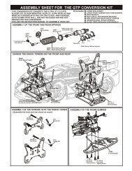
3 ASSEMBLY OF THE CENTER DIFF. MOTOR MOUNTScre wCement3x10mmScre wCement3x12mm30653Note: The width of theholes for front diff.Mount.30675940033x10mmHex Screw.....x2940043x12mmHex Screw.....x2302014 ASSEMBLY OF THE FRONT GEAR CASEScrewCementStep 1 Step 25x4mm4x12mm940365x4mmSet Screw.....x130082306733063030010940104x12mmHex Screw.....x23063030130306306x13x5mmBall Bearing.....x2ApplyGreaseApplyGrease5 ASSEMBLY OF THE FRONT GEAR CASEStep 1940094x10mmHex Screw.....x23065541009940223x18mmFlat Head Hex Screw.....x2Step 230102Notice the direction.940294x25mmFlat Head Hex Screw.....x24x10mm3x18mm4x25mm30010410103x10mm410093x28mmCap Screw.....x241010940033x10mmHex Screw.....x1940114x15mmHex Screw.....x24x16mm301602
6 ASSEMBLY OF THE KNUCKLE ARMSAssemble both right and left side.Step 1 Step 2940344x4mmSet Screw.....x23605340520360534mm940424mmNylon Nut.....x4Step 3405363405340527Knuckle ArmBushing.....x4360554mm405284052740528King Pin Screw.....x43065640527360552.5x16.8mm Pin.....x240218.....x28x12x0.3mm Washer8x12x0.3mm4x4mmS ew crCement7 ASSEMBLY OF THE FRONT SUSPENSION ARMSAssemble both right and left side.Step 1 Step 2368704x10mmSet Screw.....x2900202.5mm E-Ring.....x44x10mm360203686136690368507mm Ball.....x22.5mm368615x35mmTurnbuckle.....x2306572.5mm1•1Approx. 9.5mm36850361703x44.3mm Arm Shaft.....x2361708 ASSEMBLY OF THE FRONT SUSPENSION ARMSAssemble both right and left side.Step 1 Step 2940413mm Nylon Nut.....x23mm3mm940083x25mmHex Screw.....x2361713mm3mm900213mm E-Ring.....x8366404x47mm Arm Shaft.....x23x25366403mm361714x74.1mm Arm Shaft.....x2Insert the front drive shaft intocap joint before assembly.3
12 ASSEMBLY OF THE SERVO SAVER ONTO GEAR CASEStep 1 Step 23x15mm400393x10mmScrewCement3x15mm940033x10mmHex Screw.....x240039940213x15mmFlat Head Hex Screw.....x4ScrewCement3x15mm400393mmTapered Washer(Alum.) .....x44003913 ASSEMBLY OF THE REAR GEAR CASEStep 1 Step 2ScrewCement5x4mm3063030082940365x4mmSet Screw.....x1ApplyGrease30630306306x13x5mmBall Bearing.....x23013030010ApplyGrease14 ASSEMBLY OF THE REAR GEAR CASEStep 1 Step 2940223x18mmFlat Head Hex Screw.....x23x18mm30351940274x16mmFlat Head Hex Screw.....x230649300104x16mm940294x25mmFlat Head Hex Screw.....x24x25mm303515
15 ASSEMBLY OF THE REAR GEAR CASEStep 1 Step 2940193x10mmFlat Head Hex Screw.....x141009340333x20mm30270940063x18mmHex Screw.....x2410103x10mm410093x18mm302703027030270940073x20mmHex Screw.....x4410103027030270410093x28mmCap Screw.....x2302703x18mm3x20mm16 ASSEMBLY OF THE WING STAY AND REAR WHEEL HUB*Builds two rear wheel hubs for use.Step 1Step 2940365x4mmSet Screw.....x23mm940114x15mmHex Screw.....x236082360533608136055900183x25mmCap Screw.....x24x15mm3mm30656940413mm Nylon Nut.....x2360535x4mm360552.5x16.8mmPin.....x23x25mm4x15mm17ASSEMBLY OF THE REAR WHEEL HUB AND UPPER ARM RODAssemble both right and left side.Step 1Step 240065368704x10mmSet Screw.....x234063368504x10mm940013x5mmHex Screw.....x2340633686140065368503x5mm340633x9.5x4mmPlastic Washer.....x4340551:1Approx. 18.9mm340553x42.6mm Arm Shaft.....x2340636
18 ASSEMBLY OF THE REAR LOW ARMS INTO GEAR BOXAssemble both right and left side.Step 1Step 2940413mm Nylon Nut.....x4900213mm E-Ring.....x43mm3x18mm3x25mm940063x18mmHex Screw.....x23mm3mm940083x25mmHex Screw.....x23mm361713405419 ASSEMBLY OF THE REAR STABILIZER940023x8mmHex Screw.....x23x8x0.8mm340273x8x0.8mm940403x8x0.8mmWasher.....x23x8mm20 ASSEMBLY OF THE REAR STABILIZER RODSAssemble both right and left side.Makes two rods for left and righthand-side940333x3mmSet Screw.....x230341940353x8mmSet Screw.....x23x8mm40199 3x3mm40199940063x18mmHex Screw.....x2304033x18mm7
21 ASSEMBLY OF THE FRONT GEAR CASE ONTO CHASSIS940193x10mmFlat Head Hex Screw.....x230240940233x25mmFlat Head Hex Screw.....x230676940264x12mmFlat Head Hex Screw.....x24x12mm940274x16mmFlat Head Hex Screw.....x44x16mm4x16mm3x10mm3x25mm22 ASSEMBLY OF THE CENTER DIFF. ONTO CHASSISInsert drive shaft into capjoint before assemblycenter diff.36100 (90mm)940264x12mmFlat Head Hex Screw.....x3940274x16mmFlat Head Hex Screw.....x24x16mm4x12mm8
23 ASSEMBLY OF THE REAR GEAR CASE ONTO THE CHASSISInsert drive shaft into capjoint before assemblingcenter diff.36100 (86.5mm)940233x25mmFlat Head Hex Screw.....x24x16mm3x25mm940274x16mmFlat Head Hex Screw.....x44x16mm24ASSEMBLY OF THE STONE GUARDAssemble both right and left side.410333x10mm940193x10mmFlat Head Hex Screw.....x63x10mm3x10mm9
25ASSEMBL Y OF THE REAR CENTER BRACE3x12mm30686306864x20mm4mm940424mm Nylon Nut.....x2940043x12mmHex Screw.....x2940124x20mmHex Screw.....x14x16mm940274x16mmFlat Head Hex Screw.....x126 ASSEMBLY OF THE MAGIC TAPE INTO BATTERY CASEStep 1 Step 2306623066310
27 ASSEMBLY OF THE ELECTRIC SPEED CONTRTOLDouble side tape(Not Included)Electronic Speed Control(not included)28 ASSEMBLY OF THE BATTERY TRAY BRIDGE ONTO BATTERY CASE3x8mm306623x10mm940023x8mmHex Screw.....x230662940033x10mmHex Screw.....x23066229 ASSEMBLY OF THE ELECTRIC SPEED CONTROL WIRE INTO RADIO CASEStep 1 Step 211
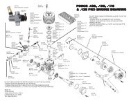
36 MOTOR INSTALLElectric Motor(Not Included)30670-(12T)30664-(13T)30665-(14T)30666-(15T)30667-(16T)30668-(17T)Step detail*Approx. 20mm4x4mm940344x4mmSet Screw.....x137 MOTOR INSTALL940383x12mmCap Screw.....x23x12mmDo NotOver Tighten3x8x0.8mm940403x8x0.8mmWasher.....x2EnsureFreeMovementTighten the 3x12mm screwtemporary.38 ADJUST MOTOR AND SPUR GEAR MAINTENANCEEXTREMELY IMPORTANTNotebook paperTightenPUSHInsert a piece of notebook paper betweenspur gear and pinion gear to make correctgear mesh.TightenAdjust the motor position to get proper gear mesh.To get a perfect gear mesh , place a piece of notebook paperbetween the gears and tighten the motor mount screws.The spur gear will strip if the gear mesh is wrong.14
39 ASSEMBLY OF THE SHOCKS40060Assemble both left and right sides.400602.6x6x0.5mm410112.6x6x0.5mm2.6x6x0.5mm410112.6x6x0.5mmStep detailHold the shock rod at top of exposedthread with side cutting needle nosed pliers.Be careful not to damage the shockshaft.40054 (SHORT) 40055 (LONG)Do NotOver TightenUse tools to tighten as shown.400602.6mmNylon Nut.....x2Step detail Step detail Step detail940592.6x6x0.5mmWasher.....x4FRONT SHOCKREAR SHOCK40ASSEMBLY OF THE SHOCKS41008Assemble both left and right sides.4100841012(2mm)410121mm Washer.....x4Oil41012(2mm)4101241012(1mm)Oil4101241012(1mm)410124101240113410122mm Washer.....x440113OilOil410123.5mm O-Ring.....x841003 (SHORT)41004 (LONG)40113P10 O-RING.....x4FRONT SHOCKREAR SHOCK41 ASSEMBLY OF THE SHOCKSAssemble both left and right sides.(LONG)EXTREMELY IMPORTANT(SHORT)OilOilDo not push the shockshaft straight down;O-ring can be damaged.Slowly twist the shockshaft down to thebottom.(SHORT)(LONG)FRONT SHOCKREAR SHOCK15
SHO CK OIL42 ASSEMBLY OF THE SHOCKSAssemble both left and right sides.Step 141007Step 2OilOil41006 OilStep detailFit the o-ring into groove beforeassembly.TOP41007P10 O-RING.....x4FRONT SHOCKREAR SHOCK43 ASSEMBLY OF THE SHOCKSAssemble both left and right sides.30403Step detail3040340643Step detail4064328mm37.5mmDo NotOver TightenDo NotOver TightenAttention distance.14mm304036mm Ball.....x4FRONT SHOCKREAR SHOCKUse tools to tighten as shown becareful not to scratch the shock shaft.44 SETTING THE SHOCK REBOUND TO 100% (HIGH REBOUND)Assemble both left and right sides.Step 1 Step 2Step 3 Step 441013TIGHTENED HALF WAY 50% TIGHTENED 100%41005Step detailStep 5Step 63~5xUP & DOWNTimeLeave the filled shock vertically for severalminutes with the shock shaft fully extended.The remaining air bubbles will release.16
45 SETTING THE SHOCK REBOUND TO 50% & 0%(MEDIUM REBOUND & LOW REBOUND)TIGHTENED HALF WAY 50%TIGHTENED 100%TIGHTENED HALF WAY 50% TIGHTENED 100%Step 1 Step 250%Step 3 Step 1 Step 2 Step 350%46 ASSEMBLY OF THE SHOCKS SPRINGStep 2 Step 3Step 1 Step 2Step 14005841015(SHORT)41015(LONG)Cut 7mm410084005841008FRONT SHOCKREAR SHOCK47 ASSEMBLY OF THE SHOCKSINTO THE SHOCK STAY4064340643940413mm Nylon Nut.....x43mm940403x8x0.8mmWasher.....x43x8x0.8mm3x20mm3mm3x8x0.8mm3x20mm940073x20mmHex Screw.....x4FRONT SHOCKREAR SHOCK17
48 ASSEMBLY OF THE TIRES AND WHEELSINST TStep 2Step 1ANGL U EMake four tires that are the same.80025Step detailINSTANTGLUEStep 3Agglutination placeUse " Instant glue " and draw a round therim where it attaches the tire . When it is dryglue the other side of the rim.86056Repeat the step and ensure the rim and tire arefully glued.49 ASSEMBLY OF THE TIRE ONTO THE FRONTKNUCKLE AND REAR HUBAssemble both left and right sides.4055040550Wheel Nut.....x4To tighten the Wheel Nut you can alsouse 17mm Wheel Nut Tool.(10801)50 ASSEMBLY OF THE WING16015 WHITE16016 YELLOW16017 RED16018 BLACK16019 ORANGE3x12mm3027026.5mm 26.5mmDrill two 7mm holes for mounting.940043x12mmHex Screw.....x218
51 BATTERY INSTALLIf use hard case battery , make a hole as picture shown.15mm8mmFollow the manual instruction provided by ESCmanufacturer to install the wire.52 MAKING HOLES AND CUTTING ON THE BODY SHELLBody Reamet (not included)Step 1 10806 BLACKStep 210807 BLUEFor electric speed control cooling hole.Make 6mm hole31143Make 7.5mm holes on the body, Body Mountas shown.Cut the body shelll as shown.53WASH THE INSIDE OF THE BODY SHELLStep 1 Step 2Wash the inside of the body shell with mild detergent,and then rinse and dry thoroughly.19
54 PAINTING BODY SHELLMask the windows on the inside with masking tape.55 PAINTING BODY SHELLPaint the body with polycarbonate spray paints.S p ray Pain tWhen the paint is dry, remove the maskingtape.When you have finished painting, peel offthe external protective films.56 MOUNTING THE BODY SHELL311593115920
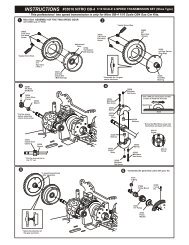
ULTRA <strong>LX</strong>2 ELECTRIC POWEREDEXPLODED VIEW30540367403068636741303613674036743367423036136742306583674036850367003674036790400383038036700400393015130102306553015141010306893001030082B-B304033602030130368503686136690A-A40199300103065730403 3617034027 30341340533617130160405284052740536361714052030240405284052730656C-C4055021
3056040642306623066230665-(14T)374103066236100 (86.5mm)3066138280(3x36mm)30401304113066230653E-E3067530401306613066236100 (90mm)30201304114103330676E-E3076930773307693066230777306633091130761306203091130662301103076930777307613062022
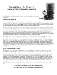
SETTING GUIDEFRONT CAMBER ANGLE SETTINGREAR CAMBER ANGLE SETTINGPositive Negative+ -- +Positive Negative+ -- +TurnbuckleTurnbucklePlace the model car on flat surface. Raise the chassis to its maximum clearancebefore the wheels leave the ground.Adjust the length of the front and rear upper arms so that the wheels are vertical to theground.Adjust the camber angle by turning the turnbuckle rod on the upper arms clockwise or counter-clockwise.(We suggest to use zero degree for the front and 1.5 degree negative for the rear.)FRONT TOE-IN AND TOE-OUT SETTINGNEUTRAL POSITIONTOE-INTOE-OUTTOE-OUTDifferent shock positions will result in firmer or softer response of thesuspension system.Install the shock in an inward angle will cause softer rebound. Softer or firmersuspension system will lead to different steering response.Adjust the shock angle positions according to track conditions.FRONT SHOCK ANGLE SETTINGSoft1 2 3FirmSteering RodREAR SHOCK ANGLE SETTING123SoftFirm front suspension, less steering.Soft front suspension, more steering.Soft1 2 3FirmFirmAdjust the length of front steering rod tochange the toe angle.Making the tie rod longer will make fronttires toed in.Response will be slower and may over steer.Making the tie rod shorter will make fronttires toed out.Response will be quicker and may under steer.12SoftFirm rear suspension, over steering.Soft rear suspension, under steering.Firm
34302 ULTRA <strong>LX</strong><strong>2e</strong> PARTS LISTOFNA DESCRIPTIONS RETAIL OFNA DESCRIPTIONS RETAIL16015 HI FORCE WING, 1/8 WHITE 15.95 36020 FRONT UPPER ARMS, 2 PCS. 5.9530010 GEARBOX, ULTRA SERIES 14.95 36053 BEARING, 8x16mm, PAIR 12.9530082 CAP JOINTS, 6mm, 2 PCS. 9.95 36055 PIN, 2.5x17mm, HEX HUBS, 4PCS 3.9530102 BODY MOUNT POSTS, 2 PCS. 0.95 36055 PIN, 2.5x17mm, HEX HUBS, 4PCS 3.9530110 SPUR GEAR,(NYLON) ULTRA 7.95 36081 REAR UP-RIGHT (8mm BEARING) PR 12.9530120 LARGE BEVEL GEAR,44T 10.95 36082 REAR AXLES, 8mm PAIR 10.9530121 BEVEL MOUNTING HARDWARE,MISC 1.95 36100 CENTER DOGBONES,SET 86.5,90mm 16.9530130 PINION GEAR,14T ULTRA 14.95 36170 ARM PINS, 3mm 4PCS <strong>LX</strong>1 7.9530160 FRONT PLATE, ARM PIN HOLDERS 4.95 36171 ARM PIN 4x74.1mm <strong>LX</strong>1 & X2T 5.9530201 CENTER, DIFF MOUNT, NEW TYPE 13.95 36640 ARM SHAFT, 4mm, SHORT, 2PCS 9.9530240 FRONT BUMPER, ULTRA CHASSIS 7.95 36700 STEERING BALL END, 7mm, 8PCS. 6.9530270 WING STAY,REAR,PLASTIC 13.95 36741 SPRING, SERVO SAVER NEW HARD 3.9530341 BALL END WITH COLLAR, 6mm 3.95 36742 BUSHING, SERVO SAVER 1.9530351 REAR ARM HOLDER 3PCS 3.95 36743 E-CLIP, 6MM SERVO SAVER 2.9530361 SERVO SAVER SHAFT 5.95 36760 FRONT PLATE JOINT 9.9530380 SERVO SAVER POSTS, 2 PCS. 4.95 36790 4x46MMTURNBUCKLES,4PCS. 10.9530401 STEERING ENDS, PLASTIC 6 PCS. 2.95 36850 7mm BALL, 6 PCS. 3.9530403 6mm BALL, STEEL (NO COLLAR) 4.95 36861 5x40mm TURNBUCKLES, 2 PCS BLK 6.9530411 6mm BALLS w/COLLAR,STEERING 6P 4.95 37410 BODY CLIPS, 10 PCS. SMALL JL10 3.9530620 BEARING KIT, 7x19mm, 6 PCS. 29.95 38280 TURNBUCKLES, 3X36MM 2PCS 5.9530630 BEARING KIT, 6x13mm 12PCS. 59.95 40038 BALLS, 7MM 4PCS. 9.9530649 SHOCK TOWER REAR <strong>LX</strong>1 H.C. 11.95 40039 TAPPER CONE WASHERS,3MM 3.9530653 CENTER TOP PLATE <strong>LX</strong>1 H.C. 6.95 40053 SHOCK BODY REAR,THREADED,2PCS 59.9530656 WHEEL HUB, <strong>LX</strong>1, PICCO 9.5 H.C. 11.95 40054 SHOCK SHAFTS,3.5m FR 13/16mm 7.9530657 LOWER ARM,FRONT, <strong>LX</strong>1 13.95 40055 SHOCK SHAFTS,3.5m RR 13/16mm 7.9530658 SERVO SAVER CONNECTOR H.C. <strong>LX</strong>1 6.95 40058 SHOCK BOOTS,SILICON 9.9530661 SERVO HORN HEAVY DUTY BLACK 4.95 40060 SHOCK PISTON LOCKNUT,2.5mm,4PC 4.9530662 BATTERY CASE,RX BOX <strong>LX</strong>-1e 19.95 40065 BALL ENDS, PLASTIC, REAR UPPER 4.9530663 BATTERY VELCRO STRAPS <strong>LX</strong>-1e 9.95 40113 O-RING P-10 FOR X1-CR,9.5 SHCK 1.9530665 PINION 14T 5MM SHAFT 12.95 40199 BALL END,STEERING,PLASTIC,6mm 7.9530673 FRONT ARM HOLDER,H.C. <strong>LX</strong>-1 12.95 40520 KNUCKLE ARM, L & R <strong>LX</strong>-2 19.9530674 SERVO SAVER PLASTIC SET <strong>LX</strong>-1 7.95 40527 KNUCKLE ARM BUSHING <strong>LX</strong>-2 4.9530675 MOTOR MOUNT,CNC, <strong>LX</strong>-1e 29.95 40528 KING PIN SCREW <strong>LX</strong>-2,X1X,NEXX8 1.9530676 CHASSIS H.C. <strong>LX</strong>-1e 89.95 40536 FRONT C HUB <strong>LX</strong>-2,X1X,X2,NEXX8 11.9530686 CENTER BRACE <strong>LX</strong>-2 PLASTIC 9.95 40550 WHEEL NUT 17mm <strong>LX</strong>-2 4.9530751 CASE, DIFF (K), FRONT or REAR 9.95 40642 ANTENNA , FIXING NUT 2.9530761 CASE, DIFF CASE (K), CENTER 9.95 40643 PLASTIC SHOCK PARTS,13/16mm<strong>LX</strong>2 9.9530769 DIFF GEAR,SILVER BEVEL,SET 4mm 14.95 41003 SHOCK BODY FRONT 16MM PAIR 29.9530773 CROSS PIN AXLES, 4mm STEEL 3.95 41004 SHOCK BODY REAR 16MM PAIR 29.9530776 WASHER, 4x10x0.2mm 4PCS. 1.95 41005 SHOCK CAP 16MM 4PCS. 22.9530777 SEAL, O-RING DIFF CASE 3.95 41006 SHOCK SPRING ADJ. 16MM 4PCS. 14.9530779 MISC. PARTS, ULTRA DIFF 9.95 41007 O-RING 19x1.5MM 16MM 4PCS. 4.9530780 PINS, 2X12.8mm FOR DIF 2PCS 3.95 41008 PLASTIC SHOCK PARTS 16MM SET 12.9530901 CAP JOINT W/SHAFT F/R DIFF 11.95 41009 CAP SCREWS 3X28MM 4PCS. 2.9530911 CAP JOINT W/SHAFT, BRAKE 11.95 41010 SHOCK BALL END POST LONG 4PCS 11.9531143 BODY, CLEAR ULTRA <strong>LX</strong><strong>2e</strong> 39.95 41011 SHOCK PISTON 16MM 8PCS. 10.9531159 BODY CLIPS, CHROME 4.95 41012 REPAIR KIT FOR 16MM SHOCK 9.9534014 BRACE, FRONT CHASSIC,ULTRACOMP 3.95 41013 PRESSURE TOP ORANGE 16MM 4PCS. 7.9534027 ANTI-ROLL BAR KIT, U.COMP,<strong>LX</strong>1 3.95 41022 SPRING .58 REAR 16MM WHITE 9.9534054 SHAFT, REAR DOG BONE 93mm PR. 15.95 41033 STONE GUARDS X2T 15.9534055 PINS, LOWER REAR ARMS 3x42.6mm 15.95 80025 TIRES, TRIAD 1/8 BUGGY W/FOAM 24.9534063 FRONT & REAR LOWER ARMS 13.95 86056 17mm TrueLITES DISH, WHT 6PACK 19.95
34302 ULTRA <strong>LX</strong><strong>2e</strong> OPTION PARTSOFNA DESCRIPTIONS RETAIL10231 DIFF OIL,SILICON 1000 WT 8.9510232 DIFF OIL,SILICON 3000 WT 8.9510233 DIFF OIL,SILICON 5000 WT 8.9510234 DIFF OIL,SILICON 7000 WT 8.9510235 DIFF OIL,SILICON 10,000 WT 9.9510236 DIFF OIL,SILICON 30,000 WT 9.9510237 DIFF OIL,SILICON 50,000 WT 9.9510238 DIFF OIL,SILICON 120,000 WT 9.9510239 CA TIRE GLUE,Rubber to Plastic 5.9510772 SERVO HORN,CNC,23T AIRTRONICS 10.9510773 SERVO HORN,CNC,DBL ARM,23T AIR 11.9510774 SERVO HORN,CNC,24T HITEC 10.9510775 SERVO HORN,CNC,DBL ARM 24T HIT 11.9510776 SERVO HORN,CNC,25T FUTABA 10.9510777 SERVO HORN,CNC,DBL ARM 25T FUT 11.9510994 SERRATED LOK NUT,17mm 1/8TH 4P 15.9516016 HI FORCE WING, 1/8 YELLOW 15.9516017 HI FORCE WING, 1/8 RED 15.9516018 HI FORCE WING, 1/8 BLACK 15.9516019 HI FORCE WING, 1/8 ORANGE 15.9530664 PINION 13T 5MM SHAFT 12.9530666 PINION 15T 5MM SHAFT 12.9530667 PINION 16T 5MM SHAFT 12.9530668 PINION 17T 5MM SHAFT 12.9530774 CROSS PIN AXLES, 4mm ALUM 6PCS 9.9533991 PCR REAR SHOCK TOWER ULTRA 24.9533995 PCR STEERING LINK PLATE ULTRA 14.9533996 PCR UPPER PLATE, FRONT DIFF UL 15.9533997 PCR CENTER DIFF. TOP PLATE ULT 15.9541014 SPRING 16MM SUPER SOFT YEL SET 17.9541016 SPRING 16MM BUGGY SILVER SET 17.9541017 SPRING 16MM HARD GRAY SET 17.9541018 SPRING 16MM TRUGGY BLUE SET 17.9541020 SHOCK BALL END POST L.W. LONG 14.9541021 SPRING .52 REAR 16MM YELLOW 9.9541023 SPRING .59 REAR 16MM BLUE 9.9541024 SPRING .60 REAR 16MM SILVER 9.9541025 SPRING .64 REAR 16MM GRAY 9.9541026 SPRING .66 FRONT 16MM YELLOW 9.9541028 SPRING .71 FRONT 16MM BLUE 9.9541029 SPRING .74 FRONT 16MM SILVER 9.9541030 SPRING .88 FRONT 16MM GRAY 9.9541116 CNC ALUM. BALLS SET HARDCOATED 24.9540570 STEERING KNUCKLE CNC H.C. 99.9586057 17mm TrueLITES DISH, YEL 6PACK 19.9586058 17mm TrueLITES DISH, ORG 6PACK 19.95
OWNER’S REGISTRATION CARDOFNA Racing congratulates you on your purchase of our fine OFNA Product. With proper maintenance and handlingthis kit will provide many hours of enjoyment.The registration card should be filled out and mailed to OFNA Racing within 10 days of purchase date.In the event that the kit is incomplete or component parts are broken due to error in manufacturer, contact yourdealer from which you purchased the kit for replacement part or call OFNA at (949) 586-2910 for your nearest dealerlocation. Other items such as radio and engine other covered by individual warranties.IMPORTANT!Please print or type, filling in the information listed below and mail immediatelyMAIL TO:OFNA RACING7 VANDERBILTIRVINE, CA. 92618TEL: (949) 586-2910REGISTRATION CARDWrite in Your Model Name and Part NumberRACER’S NAME TEL:( )ADDRESSCITY STATE ZIPDEALER’S NAME TEL: ( )ADDRESSCITY STATE ZIPOFNA7 VanderbiltIrvine, Ca. 92618