Self Assembly in Space Using Behaviour Based Intelligent ...
Self Assembly in Space Using Behaviour Based Intelligent ...
Self Assembly in Space Using Behaviour Based Intelligent ...

Create successful ePaper yourself
Turn your PDF publications into a flip-book with our unique Google optimized e-Paper software.
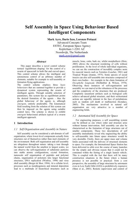
<strong>Self</strong> <strong>Assembly</strong> <strong>in</strong> <strong>Space</strong> Us<strong>in</strong>g <strong>Behaviour</strong> <strong>Based</strong><br />
<strong>Intelligent</strong> Components<br />
Abstract<br />
This paper describes a novel control scheme<br />
termed ‘equilibrium shap<strong>in</strong>g’ for the control of a<br />
swarm of spacecraft <strong>in</strong> both flat and curved space.<br />
This control scheme allows the <strong>in</strong>telligent and<br />
autonomous control of an arbitrary number of<br />
elements, suitable for example to self-assembly or<br />
formation fly<strong>in</strong>g applications.<br />
The control scheme employs three basis<br />
behaviours that are summed together to provide a<br />
dynamical system represent<strong>in</strong>g the swarm of<br />
<strong>in</strong>telligent agents. Through suitable selection of<br />
parameters, this system has as equilibrium po<strong>in</strong>ts<br />
the desired formation of the agents – thus the<br />
global behaviour of the agents is, although<br />
emergent, entirely predictable. The k<strong>in</strong>ematical<br />
field result<strong>in</strong>g from the solution of this system can<br />
then be imposed on the agents us<strong>in</strong>g suitable<br />
control laws. The scheme is shown to exhibit<br />
emergent behavioural artifacts typical of a swarm<br />
<strong>in</strong>telligent approach.<br />
1 Introduction<br />
1.1 <strong>Self</strong> Organisation and <strong>Assembly</strong> <strong>in</strong> Nature<br />
<strong>Self</strong> assembly can be considered a sub-doma<strong>in</strong> of self<br />
organisation, where lower-level components actually form<br />
structures out of themselves rather than <strong>in</strong>ert elements of<br />
the environment. Both self organisation and self assembly<br />
are ubiquitous throughout nature: tak<strong>in</strong>g a tour through<br />
the natural world from the smallest to largest scales, we<br />
can observe the self-organisation of subatomic particles<br />
<strong>in</strong>to stable atomic configurations, crystal formation,<br />
nanoscale self organisation of peptides and polymer<br />
cha<strong>in</strong>s, organisation of polymers <strong>in</strong>to larger functional<br />
structures, DNA replication (W<strong>in</strong>free, 1998) and virus<br />
shell assembly (Berger & Shor, 1994). At a cellular level,<br />
processes such as morphogenesis and m<strong>in</strong>eral deposition<br />
lead to a multitude of hiearchical structures such as<br />
Mark Ayre, Dario Izzo, Lorenzo Pettazzi<br />
Advanced Concepts Team<br />
ESTEC, European <strong>Space</strong> Agency<br />
Keplerlaan 1-2201 AZ<br />
Noordwijk, The Netherlands<br />
mark.ayre@gmail.com<br />
muscle, bone, cut<strong>in</strong>, bark etc, whilst morphallaxis (Hotz,<br />
2003) allows the structural reorder<strong>in</strong>g of cells without<br />
proliferation. At the level of whole <strong>in</strong>dividual organisms,<br />
we can see the construction of <strong>in</strong>credibly complex nests<br />
by eusocial <strong>in</strong>sects such as Termites (Luscher, 1961) and<br />
Tropical Wasps (Jeanne, 1975). Some species of social<br />
<strong>in</strong>sects can also self-assemble <strong>in</strong>to structures composed of<br />
their own bodies – for example <strong>in</strong> the cha<strong>in</strong> formation of<br />
Oecophylla long<strong>in</strong>oda (Holldobler & Wilson, 1978).<br />
Observ<strong>in</strong>g these <strong>in</strong>stances of self-organisation and<br />
assembly we can marvel at the robustness of the processes<br />
and the complexity of the structures that are produced.<br />
Completely unsentient artifacts such as biological cells<br />
achieve advanced global structure, and their orchestrated<br />
actions are superbly tolerant <strong>in</strong> the face of pertubations<br />
such as random cell death or malfunction (Kondacs,<br />
2003). The mechanisms <strong>in</strong>volved <strong>in</strong> natural self<br />
organisation are very attractive to a number of<br />
eng<strong>in</strong>eer<strong>in</strong>g fields.<br />
1.2 Automated <strong>Self</strong> <strong>Assembly</strong> for <strong>Space</strong><br />
For eng<strong>in</strong>eer<strong>in</strong>g purposes, a self assembl<strong>in</strong>g system<br />
can be def<strong>in</strong>ed as one where order and structure arise<br />
without human <strong>in</strong>tervention. <strong>Self</strong> assembly can also be<br />
characterised as the formation of large structures out of<br />
smaller components. These two descriptions of self<br />
assembly immediately reveal why eng<strong>in</strong>eer<strong>in</strong>g the ability<br />
to self-assemble <strong>in</strong>to future space structures would be<br />
very desirable. Firstly, there are upper mass and volume<br />
limits associated with the delivery of structural elements<br />
to space. For example, the International <strong>Space</strong> Station has<br />
been delivered to orbit over the course of many launches<br />
for the simple and obvious reason that it could not be<br />
conta<strong>in</strong>ed with<strong>in</strong> the fair<strong>in</strong>g of a s<strong>in</strong>gle launch vehicle.<br />
This is coupled with the fact that there will be many<br />
construction situations <strong>in</strong> the future where a human<br />
presence is not possible or practical: from a cost<br />
perspective, the assembly of large structures by astronauts<br />
even <strong>in</strong> Low Earth Orbit (LEO) is prohibitively expensive<br />
(Shen et al., 2003). Remote supervision and control of
assembly could be possible from the ground for LEO and<br />
near Earth <strong>in</strong>stances, but obviously further afield would<br />
also be impractical due to typically long communication<br />
delays.<br />
There are a number of mission concepts that will<br />
require automated assembly. The development of<br />
automated on-orbit assembly has been identified as a key<br />
requirement by the AURORA program (ESA’s<br />
exploration program). Advanced mission concepts be<strong>in</strong>g<br />
developed also rely upon the use of swarms of satellites -<br />
examples are the APIES and ANTS architectures (EADS,<br />
2004; Curtis et al., 2000). Under the gossamer spacecraft<br />
<strong>in</strong>itiative NASA has identified several new mission<br />
concepts, <strong>in</strong>clud<strong>in</strong>g very large aperture telescopes, large<br />
deployable and <strong>in</strong>flatable antennas, solar sails and large<br />
solar power collection and transmission systems. One<br />
example of this array of concepts is described <strong>in</strong> the<br />
ULTIMA studies (Zeiders, 1999), which have shown that<br />
a very attractive configuration for a very large space<br />
telescope is the three-mirror Gregorian design, shown <strong>in</strong><br />
figure 1.<br />
Figure 1 - The ULTIMA telescope configuration, image adapted<br />
from (Zeiders, 1999)<br />
The most ambitious group of structures that require <strong>in</strong>situ<br />
assembly of a number of separate components <strong>in</strong><br />
space are a number of SPS concepts such as those<br />
described <strong>in</strong> (Carr<strong>in</strong>gton, 2002). The concepts can be<br />
divided <strong>in</strong>to three primary classes, all of which are<br />
conceived of as be<strong>in</strong>g not only extremely massive and<br />
composed of literally thousands of components, but also<br />
placed at geostationary orbit far from the Earth: Figure 2<br />
shows an Integrated Symmetrical Concentrator (ISC)<br />
configuration (<strong>in</strong>com<strong>in</strong>g sunlight is collected <strong>in</strong> two large<br />
clamshells located on the ends of a mast, reflected on<br />
photovoltaic arrays located midway along the mast) with<br />
a lower reference mass of 18,000 MT.<br />
Figure 2 - ISC SPS array concept<br />
1.2.1 Systems Concepts for Automated <strong>Assembly</strong><br />
At a systems eng<strong>in</strong>eer<strong>in</strong>g level, the work done to date<br />
<strong>in</strong> realis<strong>in</strong>g automated assembly <strong>in</strong> space can be best<br />
represented by the SOLAR (<strong>Self</strong> <strong>Assembly</strong> for <strong>Space</strong><br />
Structures) project – this is based around the FIMERS<br />
concept described <strong>in</strong> (Shen et al., 2003), a system for self<br />
assembly of a space structure us<strong>in</strong>g <strong>Intelligent</strong><br />
Reconfigurable Components (IRCs), and a number of<br />
free-fly<strong>in</strong>g FIbre-rope Matchmaker Robots (FIMERs).<br />
All the IRCs are envisaged to be equipped with<br />
GPS/Gallileo receivers and wireless communication, an<br />
on-board computer that will control the <strong>in</strong>formation<br />
gather<strong>in</strong>g process<strong>in</strong>g and communications, canonical<br />
connectors to dock with other components and FIMER<br />
units, a position and orientation sensory system, an onboard<br />
controller for topology discovery, action plann<strong>in</strong>g,<br />
communication with FIMERS and other IRCs and<br />
monitor<strong>in</strong>g the progress of assembly, and auxiliary<br />
connections for fluid-gas pipes and electric connections<br />
so the structure can operate as a unified whole when fully<br />
assembled.<br />
Figure 3 – FIMER robot with two free fly<strong>in</strong>g heads, adapted<br />
from (Shen et al., 2003)<br />
The assembly of the IRCs is conceived as be<strong>in</strong>g<br />
mediated by one or more FIMER robots (figure 3). Each<br />
FIMER robot consists of a pair of robot ‘heads’ attached<br />
by a th<strong>in</strong> fibre that can be reeled <strong>in</strong> or out by the heads.<br />
Each head can fly autonomously and (de)dock with any<br />
IRC or other FIMER robots. Each head is equipped with a<br />
rotational/translational thruster system, a motor to manage<br />
reel<strong>in</strong>g of the fibre, GPS/Gallileo, wireless<br />
communications, a robotic manipulator arm, and a<br />
reconfigurable connector. The self-assembly process is
orchestrated by the Digital Hormone Model (DHM)<br />
developed for the CONRO reconfigurable robot system<br />
(Castano et al., 2002). Summarised simply, IRCs signal<br />
that they wish to dock with each other, and then call a<br />
FIMER for help. The FIMER heads attach one to each<br />
IRC and provides dock<strong>in</strong>g guidance through reel<strong>in</strong>g them<br />
together. The canonical connectors will use <strong>in</strong>fra-red to<br />
provide guidance signals for alignment <strong>in</strong> the dock<strong>in</strong>g<br />
process, as used <strong>in</strong> the CONRO system (Rubenste<strong>in</strong> et al.,<br />
2004). The mechanics of pull<strong>in</strong>g two IRCs together us<strong>in</strong>g<br />
the Fibre allow simplified control, naturally avoid<strong>in</strong>g<br />
undesirable rotation. At this f<strong>in</strong>al stage, the manipulator<br />
arms on each head will be used to provide f<strong>in</strong>e-gra<strong>in</strong><br />
control of the dock<strong>in</strong>g process. The connectors can detect<br />
their state and gather<strong>in</strong>g this <strong>in</strong>formation allows the<br />
current topology of the structure to be determ<strong>in</strong>ed. The<br />
IRCs then negotiate to decide on the next sequence of<br />
actions to take. The sequence of IRC assembly is<br />
embedded <strong>in</strong> the IRCs themselves. For a homogeneous<br />
system of IRCs, each IRC and it’s connectors do not<br />
require unique identification and sequenc<strong>in</strong>g is not<br />
required. In the case of a heterogeneous set of IRCs,<br />
unique identifiers are used for each connector (for a semihomogeneous<br />
set of IRCs, type-identifiers for generic<br />
components is sufficient).<br />
2 The Equilibrium Shap<strong>in</strong>g Approach<br />
2.1 Work to Date<br />
We are <strong>in</strong>terested here <strong>in</strong> spacecraft which have to<br />
accomplish proximity operations and have to reach, with<br />
a group of other satellites, a very tight formation, or<br />
<strong>in</strong>deed dock with those other spacecraft. A fundamental<br />
component of spacecraft swarm operations therefore<br />
<strong>in</strong>volves position and velocity control. As such, the<br />
lessons learned <strong>in</strong> terrestrial robotics research would<br />
appear to highly relevant, <strong>in</strong> particular research <strong>in</strong>to<br />
terrestrial robot path plann<strong>in</strong>g. From path plann<strong>in</strong>g<br />
approaches, the artificial potential method has to date<br />
been considered as the ma<strong>in</strong> tool that would allow a group<br />
of spacecraft to perform as required. Work us<strong>in</strong>g artificial<br />
potential fields def<strong>in</strong>ed <strong>in</strong> the space around the agent(s)<br />
has been performed through from terrestrial plath<br />
plann<strong>in</strong>g (Khatib, 1986) to spacecraft proximity and<br />
rendezvous (McInnes, 1995) and self-assembly <strong>in</strong> space<br />
(McQuade, 1997).<br />
The artificial potential method is supposed to create <strong>in</strong><br />
the space around the spacecraft (or the ‘agent’ <strong>in</strong> general)<br />
a potential field that will drive the agent far from any<br />
obstacle and towards any desired target. This method is<br />
suitable to be used both for a s<strong>in</strong>gle spacecraft and for a<br />
swarm of satellites and is capable of tackl<strong>in</strong>g the problem<br />
of the guidance of a vehicle <strong>in</strong> a time-vary<strong>in</strong>g<br />
environment. However, when comb<strong>in</strong><strong>in</strong>g multiple<br />
behaviours through the superposition of multiple potential<br />
fields, it is impossible to guarantee avoidance of<br />
undesired local m<strong>in</strong>ima.<br />
Examples of other approaches <strong>in</strong>clude work by (Ren<br />
& Beard, 2004) who <strong>in</strong>troduce the Virtual Structure<br />
method <strong>in</strong> order to design a decentralized formation<br />
scheme for spacecraft formation fly<strong>in</strong>g, whilst (Campbell,<br />
2003) applies some results from optimal control theory <strong>in</strong><br />
order to design an off-board computed procedure for the<br />
design of a formation reconfiguration method.<br />
In general all these methods have been used to design<br />
systems that have only one target configuration as a f<strong>in</strong>al<br />
objective. Therefore there is a general requirement for a<br />
method able to tackle the multi-target problem for a<br />
swarm of homogeneous agents. In such an algorithm the<br />
f<strong>in</strong>al position occupied by each agent <strong>in</strong> the target<br />
configuration should be chosen <strong>in</strong> an autonomous way<br />
between all the of possible ones accord<strong>in</strong>g to the <strong>in</strong>itial<br />
conditions imposed. Each satellite belong<strong>in</strong>g to the swarm<br />
will be then able to autonomously decide what its f<strong>in</strong>al<br />
position <strong>in</strong> the target configuration will be, exchang<strong>in</strong>g a<br />
m<strong>in</strong>imum amount of <strong>in</strong>formation with the other swarm<br />
components. This k<strong>in</strong>d of procedure can drive a selfassembly<br />
process of homogeneous agents <strong>in</strong> space and it<br />
clearly scales well with the <strong>in</strong>creas<strong>in</strong>g of the number of<br />
satellites belong<strong>in</strong>g to the swarm due to the lack of<br />
explicit global coord<strong>in</strong>ation.<br />
2.2 The Control Scheme<br />
In this section an algorithm able to lead an arbitrary<br />
number of homogeneous spacecraft towards a f<strong>in</strong>al<br />
formation by autonomously decid<strong>in</strong>g which agent will get<br />
to each position of the f<strong>in</strong>al configuration is presented.<br />
Such a method draws <strong>in</strong>spiration from behavioural<br />
robotics, and a model recently developed by (Gazi, 2003;<br />
Gazi & Pass<strong>in</strong>o, 2002), <strong>in</strong> which a k<strong>in</strong>ematical field is<br />
proposed that can lead a swarm of agents to reach a stable<br />
configuration. The result<strong>in</strong>g procedure is made up of two<br />
different steps:<br />
• A desired k<strong>in</strong>ematical field is imposed <strong>in</strong> the space<br />
around the agents belong<strong>in</strong>g to the swarm. This<br />
k<strong>in</strong>ematical field is time dependent and it assigns<br />
for each configuration, i.e. each position of each<br />
spacecraft, the desired velocity vector of each<br />
agent as a sum of different weighted contributions.<br />
• An appropriate feedback signal is def<strong>in</strong>ed to<br />
enforce the real dynamics of each spacecraft<br />
towards the desired one.<br />
In this way it is possible to keep the desired<br />
k<strong>in</strong>ematical field design separate from the control<br />
feedback design, which is arbitrary - this control scheme<br />
has been tested us<strong>in</strong>g four different steer<strong>in</strong>g laws. The<br />
velocity field used <strong>in</strong> (Gazi & Pass<strong>in</strong>o, 2002) is given by<br />
the sum of two different contributions, both of which are<br />
functions of the distance between two agents i and j. The<br />
first contribution <strong>in</strong>troduces a l<strong>in</strong>ear global attraction<br />
effect whereas the second one <strong>in</strong>troduces a local<br />
exponential repulsive effect, def<strong>in</strong>ed by:<br />
V<br />
d i<br />
⎡ ⎛ − xij.<br />
xij<br />
⎞⎤<br />
= −∑<br />
x ⎢c<br />
− b ⎜<br />
⎟<br />
j ij i i exp ⎥<br />
⎣ ⎝ k ⎠⎦<br />
(1)
Where xj is the distance between the agents, and c anb are<br />
coefficients determ<strong>in</strong>ed by the formation geometry. This<br />
approach allows a f<strong>in</strong>al desired formation to be reached<br />
only if the required distance between a generic i-j couple<br />
of spacecraft at the end of the simulation is pre-assigned.<br />
Thus the result<strong>in</strong>g system doesn't have the general<br />
capability of decid<strong>in</strong>g autonomously where each agent<br />
should go. In order to <strong>in</strong>crease the fault tolerance and the<br />
degree of parallelism of the system, the position of each<br />
swarm component <strong>in</strong> the desired f<strong>in</strong>al structure should<br />
not to be pre-assigned; this constra<strong>in</strong>t becomes a<br />
particularly important feature for swarms composed of<br />
very large numbers of elements, where exploitation of<br />
parallelism between homogeneous elements would be<br />
very desirable. In that way the f<strong>in</strong>al formation reached<br />
would be autonomously decided by the agents accord<strong>in</strong>g<br />
to the <strong>in</strong>formation that each of them can obta<strong>in</strong> by the use<br />
of sensors and would not be imposed at the beg<strong>in</strong>n<strong>in</strong>g of<br />
the manouevre.<br />
The f<strong>in</strong>al configuration can be reached <strong>in</strong> such an<br />
autonomous manner accord<strong>in</strong>g to a particular def<strong>in</strong>ition of<br />
the desired k<strong>in</strong>ematical field given from the equilibrium<br />
shap<strong>in</strong>g approach developed here. This technique consists<br />
<strong>in</strong> build<strong>in</strong>g a dynamical system that has as equilibrium<br />
po<strong>in</strong>ts all the possible configurations suitable for the f<strong>in</strong>al<br />
purpose, i.e. all the agents permutations <strong>in</strong> the f<strong>in</strong>al<br />
desired configuration.<br />
As example let us consider a situation <strong>in</strong> which a<br />
swarm of two satellites has to reach a f<strong>in</strong>al configuration<br />
made up of the two geometric positions given by:<br />
x [ 1 0 0]<br />
r , = [ −1<br />
0 0]<br />
1 =<br />
x r (2)<br />
2<br />
If the agents are identical two f<strong>in</strong>al formations will be<br />
valid, one <strong>in</strong> which agent 1 is <strong>in</strong> x1 r and agent 2 <strong>in</strong> 2 xr and<br />
one <strong>in</strong> which the f<strong>in</strong>al positions are <strong>in</strong>verted. We def<strong>in</strong>e a<br />
desired k<strong>in</strong>ematical field accord<strong>in</strong>g to the relation:<br />
r r r<br />
&r r r<br />
( ) ⇒ ( ) = 0 x f x f x (3)<br />
= e<br />
<strong>in</strong> which the xe r vector represents all the possible f<strong>in</strong>al<br />
formations achievable (<strong>in</strong> the example, both the f<strong>in</strong>al<br />
configurations <strong>in</strong> which Agent1 1 xr ⇒ and Agent2 x2 r<br />
⇒ and<br />
<strong>in</strong> which Agent1 2 xr ⇒ Agent2 1 xr ⇒ ). The desired velocity<br />
field used to obta<strong>in</strong> this effect can be written as a<br />
superposition of different contributions.<br />
Tak<strong>in</strong>g <strong>in</strong>spiration from (Brooks, 1991), three<br />
behavioural primitives required for the task of assum<strong>in</strong>g a<br />
formation <strong>in</strong> space (<strong>in</strong>clud<strong>in</strong>g assembly) have been<br />
def<strong>in</strong>ed to allow the swarm of satellites to function:<br />
Gather, Avoid and Dock. Note that this model does not<br />
take <strong>in</strong>to account control of the attitude of the agents,<br />
although this is possible, and work is currently underway<br />
to extend the repertoire of behaviours to <strong>in</strong>clude attitude<br />
control. The govern<strong>in</strong>g expressions of each basis<br />
behaviour along with some brief comments are presented<br />
below. Each contribution to the i-th agent desired velocity<br />
field establishes a relation with an agent if it has the j<br />
subscript, whereas it refers to a desired f<strong>in</strong>al position <strong>in</strong><br />
the formation (hereafter a s<strong>in</strong>k) if it has the t subscript:<br />
j<br />
(i) Gather behaviour This basis behaviour <strong>in</strong>troduces<br />
N different global attractors towards the s<strong>in</strong>ks of the<br />
desired formation. Therefore each agent has to know at<br />
each time where is the position of each po<strong>in</strong>t of the f<strong>in</strong>al<br />
formation to be achieved. The expression for this k<strong>in</strong>d of<br />
behaviour is def<strong>in</strong>ed as:<br />
r<br />
f<br />
it j<br />
gather<br />
r<br />
= −c<br />
x<br />
(4)<br />
j it j<br />
where xt j<br />
r is the distance between the i-th agent and the jth<br />
s<strong>in</strong>k ( t ). This behaviour can be written for each s<strong>in</strong>k<br />
j<br />
and for each agent and is l<strong>in</strong>ear with the distance between<br />
them. Summ<strong>in</strong>g up for one agent the contribution of each<br />
s<strong>in</strong>k it is easy to understand that all these contributions are<br />
equivalent to a s<strong>in</strong>gle global attractor po<strong>in</strong>t<strong>in</strong>g towards the<br />
center of the desired formation (figure 4).<br />
9<br />
8<br />
7<br />
6<br />
5<br />
4<br />
3<br />
2<br />
1<br />
0<br />
6<br />
4<br />
2<br />
0<br />
y<br />
−2<br />
−4<br />
−6<br />
sqrt(x 2 +y 2 )<br />
Figure 4 – The gather behaviour global attractor<br />
(ii) Avoid behaviour This basis behaviour establishes<br />
a relationship between two different agents that are <strong>in</strong><br />
proximity with each other. In such a case a repulsive<br />
contribution will assign to the desired velocity field a<br />
direction that will lead both the two agents away from<br />
each other. The expression that describes the assigned<br />
velocity for this k<strong>in</strong>d of behaviour is given below:<br />
r<br />
r x<br />
ij r r −<br />
f ( x ) = −x<br />
[ b exp(<br />
avoid<br />
ij<br />
ij<br />
k1<br />
ij<br />
)]<br />
In this relation ij<br />
x r is the distance between the two agents<br />
that are proximate and 1<br />
k is a parameter that describe the<br />
sphere of <strong>in</strong>fluence of this contribution, i.e. at what<br />
distance this behaviour would have a non-negligible<br />
effect. In order to ma<strong>in</strong>ta<strong>in</strong> the symmetry between all the<br />
agents the b parameters of the avoid behaviour all have<br />
the same numerical value (figure 5).<br />
−6<br />
−4<br />
−2<br />
x<br />
0<br />
2<br />
4<br />
6<br />
(5)
2.5<br />
2<br />
1.5<br />
1<br />
0.5<br />
0<br />
3<br />
2<br />
1<br />
0<br />
y<br />
−1<br />
−2<br />
sqrt(x 2 +y 2 ) exp(−(x 2 +y 2 ))<br />
−3<br />
−3<br />
Figure 5 – The avoid behaviour<br />
(iii) Dock behaviour This last basis behaviour<br />
expresses the local attraction of each agent towards each<br />
s<strong>in</strong>k. The component of the desired velocity field due to<br />
this behaviour has a non-negligible value only if the agent<br />
is <strong>in</strong> the vic<strong>in</strong>ity of the s<strong>in</strong>k. The parameter d determ<strong>in</strong>es<br />
the radius of the sphere of <strong>in</strong>fluence of the dock<br />
behaviour. The expression for this basis behaviour is:<br />
−2<br />
r<br />
r x<br />
ij r r − it j<br />
fdock<br />
( xit<br />
) = −x<br />
[ d exp( )]<br />
(6)<br />
j it j it j k<br />
<strong>in</strong> which aga<strong>in</strong><br />
−1<br />
2<br />
x<br />
0<br />
xit j<br />
r is the distance between the i-th agent<br />
and the j-th s<strong>in</strong>k t and k determ<strong>in</strong>es the radius of the<br />
j<br />
2<br />
sphere of <strong>in</strong>fluence of this behaviour. The values of the<br />
weight<strong>in</strong>g parameters can be different for any s<strong>in</strong>k (figure<br />
6).<br />
0<br />
−0.5<br />
−1<br />
−1.5<br />
−2<br />
−2.5<br />
3<br />
2<br />
1<br />
0<br />
y<br />
−1<br />
−2<br />
− sqrt(x 2 +y 2 ) exp(−(x 2 +y 2 ))<br />
−3<br />
−3<br />
Figure 6 – The dock behaviour<br />
Hav<strong>in</strong>g def<strong>in</strong>ed behavioural primitives for each<br />
member of the spacecraft swarm, we def<strong>in</strong>e the velocity<br />
field for each configuration of spacecraft simply by<br />
summ<strong>in</strong>g the contribution from each of the basis<br />
behaviours:<br />
r r r r<br />
ij<br />
it j it j<br />
v f + ( f + f ) , i = 1...<br />
N (7)<br />
i<br />
= ∑ ∑<br />
avoid<br />
j tj<br />
gather<br />
This strategy leads to build a dynamical system which can<br />
be sketched <strong>in</strong> the simple form:<br />
−2<br />
dock<br />
−1<br />
x<br />
0<br />
1<br />
1<br />
2<br />
2<br />
3<br />
3<br />
r<br />
x&r<br />
r<br />
= f ( x;<br />
λ)<br />
(8)<br />
The result<strong>in</strong>g dynamical system is obta<strong>in</strong>ed as a function<br />
of some parameters λ = [ cit , d b]<br />
j it , that can be evaluated <strong>in</strong><br />
j<br />
order to impose that all the f<strong>in</strong>al desired configurations<br />
are equilibrium po<strong>in</strong>ts. If e xr is the f<strong>in</strong>al target<br />
configuration to be achieved the relation that has to be<br />
fulfilled <strong>in</strong> order to impose the existence of such<br />
equilibria can be written <strong>in</strong> the compact form:<br />
r<br />
x&r<br />
r<br />
= f ( x ; λ)<br />
= 0<br />
(9)<br />
e<br />
this is the equilibrium shap<strong>in</strong>g formula, written below as<br />
a function of the distance between two different s<strong>in</strong>ks<br />
each of them occupied by an agent x r<br />
:<br />
e tit<br />
j<br />
r<br />
r r<br />
⎡ − xt<br />
x<br />
x x<br />
it<br />
⋅<br />
j tit<br />
j r r<br />
− tit<br />
⋅<br />
j tit<br />
⎤ j r<br />
∑ bexp( ) c ( x x ) d exp( ) x 0<br />
j ⎢<br />
− it − j tit<br />
⋅ j tit<br />
− j it<br />
⎥<br />
j<br />
tit<br />
= j<br />
⎢⎣<br />
k1<br />
k2<br />
⎥⎦<br />
i = 1.....<br />
N.<br />
r (10)<br />
This equation is a l<strong>in</strong>ear system made up of 3N scalar<br />
equations <strong>in</strong> 2N unknowns where the unknowns are the<br />
weight<strong>in</strong>g parameters λ . If a regular formation, or a<br />
planar formation are the target configurations, the number<br />
of <strong>in</strong>dependent scalar relations becomes ≤ 2N<br />
and the<br />
solution of the equilibrium shap<strong>in</strong>g formula can be found.<br />
Note that this evaluation theoretically only needs to be<br />
evaluated once at the beg<strong>in</strong>n<strong>in</strong>g of the maneouvre; thus <strong>in</strong><br />
pr<strong>in</strong>ciple the agents will not require updat<strong>in</strong>g of global<br />
knowledge dur<strong>in</strong>g the maneouvre (although <strong>in</strong> practice<br />
this may not be practical).<br />
This system <strong>in</strong> theory can be designed for each agent and<br />
can be thus considered as the "subjective" view of the i-th<br />
spacecraft. In this way for a system of N satellites it is<br />
possible to write N equilibrium shap<strong>in</strong>g formulas each of<br />
them represent<strong>in</strong>g the subjective k<strong>in</strong>ematical field of each<br />
agent. In figures 7, 8, 9, and 10 some examples of swarms<br />
of N agents reach<strong>in</strong>g regular formations are presented.<br />
The l<strong>in</strong>es displayed <strong>in</strong> these figures are the desired<br />
trajectories that each agent has to follow <strong>in</strong> order to reach<br />
the f<strong>in</strong>al desired configuration and as such represent the<br />
solution of the path plann<strong>in</strong>g problem given by the<br />
velocity field.<br />
x (m)<br />
y (m)<br />
z (m)<br />
5<br />
0<br />
−5<br />
−10<br />
−10<br />
−5<br />
0<br />
5<br />
10<br />
15 −5<br />
0<br />
5<br />
10<br />
15
Figure 7 – Trajectory plot of four spacecraft adopt<strong>in</strong>g a<br />
formation<br />
5<br />
0<br />
−5<br />
−10<br />
−15<br />
−20<br />
−25<br />
−30<br />
−30<br />
−20<br />
−10<br />
0<br />
10<br />
20<br />
30<br />
Figure 8 – Trajectory plot of six spacecraft assum<strong>in</strong>g a regular<br />
hexagonal formation<br />
z(m)<br />
10<br />
5<br />
0<br />
−5<br />
−10<br />
10<br />
y(m)<br />
0<br />
−10<br />
−15<br />
−10<br />
−5<br />
x(m)<br />
Figure 9 – Trajectory plot of eight spacecraft adopt<strong>in</strong>g a regular<br />
cube formation<br />
z (m)<br />
12<br />
10<br />
8<br />
6<br />
4<br />
2<br />
0<br />
−2<br />
−4<br />
−6<br />
−8<br />
−10<br />
−5<br />
x (m)<br />
0<br />
5<br />
−20<br />
0<br />
−10<br />
5<br />
0<br />
10<br />
10<br />
20<br />
15<br />
0<br />
−5<br />
10 −10<br />
y (m)<br />
Figure 10 - Trajectory plot of twelve spacecraft adopt<strong>in</strong>g a<br />
regular formation<br />
Dur<strong>in</strong>g the simulations emergent behaviours may be<br />
observed due to the <strong>in</strong>teraction between the basis<br />
behaviours. These behaviours <strong>in</strong>clude wait<strong>in</strong>g for other<br />
agents to adopt their position, and coord<strong>in</strong>ated avoidance<br />
between agents.<br />
2.2.1 Modification for a Gravitational Field<br />
In the absence of a gravitational field, the velocity<br />
field designed <strong>in</strong> the previous section allows the<br />
spacecraft to reach the f<strong>in</strong>al formation follow<strong>in</strong>g<br />
trajectories that are straight l<strong>in</strong>es <strong>in</strong> long parts of the<br />
simulation (i.e when only the gather behaviour has a nonnegligible<br />
value). In field-free space this is of course<br />
appropriate and efficient: however, <strong>in</strong> field-space, the<br />
30<br />
5<br />
desired velocity field should be modified to take <strong>in</strong>to<br />
account and exploit the natural trajectories that exist<br />
between two po<strong>in</strong>ts on different orbits. The desired<br />
velocity that accomplishes this will here be found by<br />
substitut<strong>in</strong>g the l<strong>in</strong>ear gather behaviour def<strong>in</strong>ed by<br />
equation 4 with a new one. The start<strong>in</strong>g po<strong>in</strong>t for the<br />
design of the new gather behaviour is the well known<br />
system of Hill’s Equations:<br />
2<br />
⎧&x<br />
&−<br />
2ωy&<br />
− 3ω<br />
= 0<br />
⎪<br />
⎨ &y<br />
& + 2ωx&<br />
= 0<br />
⎪<br />
2<br />
⎩<br />
&z<br />
&+<br />
ω z = 0<br />
(11)<br />
These equations allow as their solution the follow<strong>in</strong>g<br />
relation:<br />
⎡ρ<br />
⎤ ⎡A(<br />
τ ) B(<br />
τ ) ⎤⎡ρ<br />
0⎤<br />
⎢ ⎥ = ⎢ ⎥⎢<br />
⎥<br />
⎣ & ρ⎦<br />
⎣C(<br />
τ ) D(<br />
τ ) ⎦⎣<br />
& ρ0⎦<br />
(12)<br />
With ⎡ρ<br />
⎤ be<strong>in</strong>g the non dimensional state space vector,<br />
⎢ ⎥<br />
⎣ & ρ⎦<br />
τ the non dimensional time and A, B, C, and D have<br />
well known forms (see McQuade, 1997). Equation 12 can<br />
now be used <strong>in</strong> order to def<strong>in</strong>e a new gather behaviour<br />
that could allow each agent to exploit the gravity field <strong>in</strong><br />
order to reach the f<strong>in</strong>al desired configuration. If one wants<br />
to impose that a satellite will reach a certa<strong>in</strong> po<strong>in</strong>t ρ d <strong>in</strong><br />
the relative space <strong>in</strong> a certa<strong>in</strong> timeτ d , the follow<strong>in</strong>g<br />
relation has to be valid:<br />
ρ = ρ(<br />
τ ) = A(<br />
τ ) ρ + B(<br />
τ ) & ρ<br />
(13)<br />
d<br />
d<br />
d<br />
0<br />
This relation assigns for each position <strong>in</strong> space ρ 0 and<br />
each desired time τ d a desired velocity vector:<br />
r<br />
−1<br />
v = & ρ = B ( ρ − A(<br />
ˆ τ −τ<br />
) ρ)<br />
d<br />
d<br />
d<br />
d<br />
0<br />
(14)<br />
<strong>in</strong> which τˆ d is the time at which at the beg<strong>in</strong>n<strong>in</strong>g of the<br />
simulation the agent is supposed to reach the position ρ d .<br />
In order to track the natural trajectory the result<strong>in</strong>g<br />
desired velocity vector depends explicitly on the time.<br />
This contribution can be added to those obta<strong>in</strong>ed by<br />
equation 5 and equation 6 and <strong>in</strong> order to build the f<strong>in</strong>al<br />
desired k<strong>in</strong>ematical field that the swarm has to follow.<br />
S<strong>in</strong>ce at the end of the assembly procedure each<br />
spacecraft will probably operate <strong>in</strong> a condition <strong>in</strong> which it<br />
is close to the other swarm components it is not possible<br />
to allow the spacecraft to have high velocities <strong>in</strong> that<br />
situation. Furthermore equation 16 becomes s<strong>in</strong>gular as<br />
long as t approaches the τˆ d value. For both these reasons<br />
the agents are not permitted to follow the natural<br />
trajectories until the end of the formation acquisition. To<br />
implement this we divide the desired k<strong>in</strong>ematical field
<strong>in</strong>to two different sections: (i) far from the desired f<strong>in</strong>al<br />
configuration, <strong>in</strong> which the gather behaviour takes <strong>in</strong>to<br />
account the gravitational force and (ii) close to the desired<br />
f<strong>in</strong>al formation, <strong>in</strong> which space can be l<strong>in</strong>earised and<br />
considered flat. The geometrical shape of the edge of<br />
these two different zones of the space can be easily set as<br />
a sphere, with a radius that can be decided by the system<br />
designer. Figure 11 shows an example of the ballistic (i.e.<br />
outer section) trajectories followed by an assembl<strong>in</strong>g<br />
group of six spacecraft.<br />
z(m)<br />
100<br />
0<br />
−100<br />
−200<br />
−300<br />
−400<br />
−500<br />
−600<br />
−700<br />
−800<br />
−1000<br />
−500<br />
0<br />
x(m)<br />
500<br />
1000<br />
1000<br />
500<br />
0<br />
−500<br />
−1000<br />
y(m)<br />
Figure 11 – The ballistic phase trajectories of an assembl<strong>in</strong>g<br />
group of six spacecraft<br />
∆ v(m/sec)<br />
1.4<br />
1.2<br />
1<br />
0.8<br />
0.6<br />
0.4<br />
0.2<br />
0<br />
1 2 3 4 5 6<br />
<strong>Space</strong>craft<br />
separated k<strong>in</strong>ematical field<br />
flat k<strong>in</strong>ematical field<br />
Figure 12 – comparison of the delta V for each of six spacecraft<br />
assembl<strong>in</strong>g <strong>in</strong>to a regular formation <strong>in</strong> curved space, us<strong>in</strong>g flat<br />
and curved space gather behaviours<br />
By exploit<strong>in</strong>g the natural trajectories that exist <strong>in</strong> curved<br />
space, substantial delta V sav<strong>in</strong>gs are made, when<br />
compared with the flat space control scheme. Figure 12<br />
shows an example of the delta V sav<strong>in</strong>g when us<strong>in</strong>g the<br />
ballistic gather behaviour <strong>in</strong> curved space.<br />
2.2.2 Implementation<br />
This control scheme can be easily embedded <strong>in</strong>to<br />
algorithms that can allow assembly of large structures <strong>in</strong><br />
space under more constra<strong>in</strong>ed conditions (e.g.<br />
heterogeneous agents, sequentiality constra<strong>in</strong>ts etc.). Two<br />
architectures have been studied with<strong>in</strong> the context of this<br />
work: The first uses the TRS scheme developed by (Jones<br />
& Mataric, 2003) to control the assembly of an arbitrary<br />
structure with sequenc<strong>in</strong>g constra<strong>in</strong>ts, and the second<br />
scheme has been developed to allow assembly of a<br />
structure by ‘slave’ robots, analogous to the FIMER<br />
robots <strong>in</strong>troduced <strong>in</strong> section 1.2.1.<br />
3 Conclusions<br />
A novel scheme for autonomous control of a swarm of<br />
spacecraft for self-assembly or formation fly<strong>in</strong>g has been<br />
presented, both <strong>in</strong> flat and curved space environments. It<br />
has been shown to exhibit <strong>in</strong>telligent emergent<br />
coord<strong>in</strong>ation at a global level (avoid<strong>in</strong>g fellow agents,<br />
wait<strong>in</strong>g for fellow agents to dock before mov<strong>in</strong>g) under<br />
tests us<strong>in</strong>g a variety of steer<strong>in</strong>g laws, despite lack of<br />
explicit coord<strong>in</strong>ation between agents. It should not only<br />
allow maximum exploitation of parallelism <strong>in</strong> systems<br />
with large numbers of homogeneous agents, but is also<br />
easily embedded with<strong>in</strong> algorithms that can coord<strong>in</strong>ate the<br />
assembly process under more constra<strong>in</strong>ed conditions.<br />
Solution of the dynamic system controll<strong>in</strong>g the agents<br />
theoretically only needs to be solved once at the<br />
beg<strong>in</strong>n<strong>in</strong>g, potentially obviat<strong>in</strong>g the requirement for<br />
cont<strong>in</strong>uous global updat<strong>in</strong>g dur<strong>in</strong>g the course of the<br />
maneouvre. Additionally, there are N dynamical systems<br />
equations for N agents, and therefore the technique scales<br />
l<strong>in</strong>early.<br />
The control scheme has been implemented <strong>in</strong><br />
Matlab/SIMULINK, us<strong>in</strong>g the Virtual Reality Modell<strong>in</strong>g<br />
Language (VRML) Toolbox to allow visualisation of the<br />
assembly process – an example storyboard of the VRML<br />
output is shown <strong>in</strong> figure 13.<br />
Figure 13 – VRML storyboard of the assembly process of 7<br />
agents around a static ‘seed’ agent<br />
Further <strong>in</strong>formation about the project and resources<br />
(<strong>in</strong>clud<strong>in</strong>g videos of the assembly process) are available<br />
at:<br />
http://www.esa.<strong>in</strong>t/gsp/ACT/biomimetics/testcases_re<br />
search_SAA.htm.<br />
References<br />
Berger, B., Shor, P. W. (1994). On the mathematics of<br />
Virus Shell <strong>Assembly</strong>. MIT Technical Note.
Brooks, R. A. (1991). Intelligence Without Reason.<br />
Proceed<strong>in</strong>gs of the 12th International Jo<strong>in</strong>t<br />
Conference on Artificial Intelligence (IJCAI-91).<br />
Campbell, M. (2003). Plann<strong>in</strong>g Algorithm for Multiple<br />
Satellite Clusters. Journal of Guidance Control and<br />
Dynamics, Vol. 26, No. 5, pp.770-780.<br />
Carr<strong>in</strong>gton, C. (2002). <strong>Space</strong> Solar Power Concepts:<br />
Demonstrations to Pilot Plants. IAC-02-R.P12.<br />
Castano, A., Behar, A., Will, P (2002). The CONRO<br />
Modules for Reconfigurable Robots. IEEE<br />
Transactions on Mechatronics, Vol. 7(4), pp.403-409.<br />
Curtis, S., Mica, J., Nuth, J., Marr, G., Rilee, M., Bath,<br />
M. (2000). ANTS (Autonomous Nano-Technology<br />
Swarm): An Artificial Intelligence Approach to<br />
Asteroid Belt Resource Exploration. Proceed<strong>in</strong>gs of<br />
the 51 st International Astronautical Congress.<br />
EADS-Astrium (2004). The APIES Mission Feasibility<br />
Study. AO/1-3846/02/NL/JA, ESA.<br />
Gazi, V. (2003). Swarm Aggregations Us<strong>in</strong>g Artificial<br />
Potentials and Slid<strong>in</strong>g Mode Control. Proceed<strong>in</strong>gs of<br />
the 42 nd IEEE Conference on Decision and Control.<br />
Gazi, V., Pass<strong>in</strong>o, K. (2002). A Class of<br />
Attraction/Repulsion Functions for Stable Swarm<br />
Aggregations. Proceed<strong>in</strong>gs of the 41 st IEEE<br />
Conference on Decision and Control.<br />
Holldobler, B., Wilson, E. O. (1978). The Multiple<br />
Recruitment Systems of the African Weaver ant<br />
Oecophylla long<strong>in</strong>oda (Latreille). <strong>Behaviour</strong>al<br />
Ecology and Sociobiology, Vol. 3, pp.19-60.<br />
Hotz, P. E., (2003). Explor<strong>in</strong>g Regenerative<br />
Mechanisms Found <strong>in</strong> Flatworms by Artificial<br />
Evolutionary Techniques Us<strong>in</strong>g Genetic Regulatory<br />
Networks. Proceed<strong>in</strong>gs of the Congress of<br />
Evolutionary Computation, Canberra.<br />
Jeanne, R. L. (1975). The Adaptiveness of Social Wasp<br />
Nest Architecture. Quarterly Review of Biology, Vol.<br />
50, pp.267-287.<br />
Jones, C., Mataric, M. J. (2003). From local to global<br />
behaviour <strong>in</strong> <strong>in</strong>telligent self-assembly. Proceed<strong>in</strong>gs of<br />
the IEEE International Conference on Robotics and<br />
Automation.<br />
Khatib, O. (1986). Real-Time Obstacle Avoidance for<br />
Manipulators and Mobile Robots. The International<br />
Journal of Robotics Research, Vol. 5, No. 1, pp.90-98.<br />
Kondacs, A. (2003). Biologically Inspired <strong>Self</strong>-<br />
<strong>Assembly</strong> of Two-Dimensional Shapes Us<strong>in</strong>g Globalto-Local<br />
Compilation. 18 th International Jo<strong>in</strong>t<br />
Conference on Artificial Intelligence, Acapulco,<br />
Mexico.<br />
Luscher, M. (1961). Air-Conditioned Termite Nests.<br />
Scientific American, Vol. 205, pp.138-145.<br />
McInnes, C., R. (1995). Autonomous Rendezvous us<strong>in</strong>g<br />
Artificial Potential Functions. Journal of Guidance<br />
Control and Dynamics, Vol. 18, No. 2, pp.237-241.<br />
McQuade, F. (1997). Autonomous Control for On-Orbit<br />
<strong>Assembly</strong> us<strong>in</strong>g Artificial Potential Functions. PhD<br />
Thesis, Department of Aerospace Eng<strong>in</strong>eer<strong>in</strong>g,<br />
University of Glasgow.<br />
Ren, W., Beard, R. (2004). A Decentralised Scheme for<br />
<strong>Space</strong>craft Formation Fly<strong>in</strong>g via the Virtual Structure<br />
Approach. AIAA Journal of Guidance, Control and<br />
Dynamics, Vol. 27, No.1, pp.73-82.<br />
Rubenste<strong>in</strong>, M., Payne, K., Will, P., Shen, W. M.<br />
(2004). Dock<strong>in</strong>g Among Independent and Autonomous<br />
CONRO <strong>Self</strong>-Reconfigurable Robots. International<br />
Conference on Robotics and Automation, New<br />
Orleans, USA.<br />
Shen, W. M., Will, P., Khoshnevis, B. (2003). <strong>Self</strong>-<br />
<strong>Assembly</strong> <strong>in</strong> <strong>Space</strong> via <strong>Self</strong>-Reconfigurable Robots.<br />
International Conference on Robotics and<br />
Automation, Taiwan.<br />
W<strong>in</strong>free, E. (1998) Algorithmic self assembly of DNA.<br />
Doctoral Thesis.<br />
Zeiders, G. W. (1999). Innovative Design Concepts for<br />
Ultralightweight <strong>Space</strong> Telescopes. Ultra Lightweight<br />
<strong>Space</strong> optics Challenge Workshop.