P - Transmission
P - Transmission
P - Transmission
- No tags were found...
You also want an ePaper? Increase the reach of your titles
YUMPU automatically turns print PDFs into web optimized ePapers that Google loves.
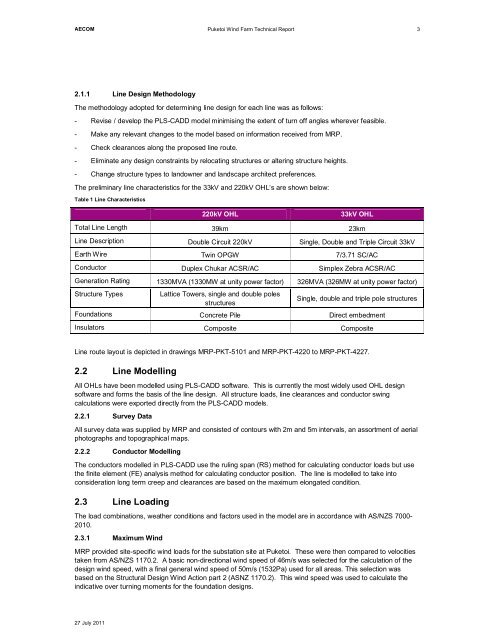
AECOMPuketoi Wind Farm Technical Report32.1.1 Line Design MethodologyThe methodology adopted for determining line design for each line was as follows:- Revise / develop the PLS-CADD model minimising the extent of turn off angles wherever feasible.- Make any relevant changes to the model based on information received from MRP.- Check clearances along the proposed line route.- Eliminate any design constraints by relocating structures or altering structure heights.- Change structure types to landowner and landscape architect preferences.The preliminary line characteristics for the 33kV and 220kV OHL’s are shown below:Table 1 Line Characteristics220kV OHL33kV OHLTotal Line Length 39km 23kmLine Description Double Circuit 220kV Single, Double and Triple Circuit 33kVEarth Wire Twin OPGW 7/3.71 SC/ACConductor Duplex Chukar ACSR/AC Simplex Zebra ACSR/ACGeneration Rating 1330MVA (1330MW at unity power factor) 326MVA (326MW at unity power factor)Structure TypesLattice Towers, single and double polesstructuresSingle, double and triple pole structuresFoundations Concrete Pile Direct embedmentInsulators Composite CompositeLine route layout is depicted in drawings MRP-PKT-5101 and MRP-PKT-4220 to MRP-PKT-4227.2.2 Line ModellingAll OHLs have been modelled using PLS-CADD software. This is currently the most widely used OHL designsoftware and forms the basis of the line design. All structure loads, line clearances and conductor swingcalculations were exported directly from the PLS-CADD models.2.2.1 Survey DataAll survey data was supplied by MRP and consisted of contours with 2m and 5m intervals, an assortment of aerialphotographs and topographical maps.2.2.2 Conductor ModellingThe conductors modelled in PLS-CADD use the ruling span (RS) method for calculating conductor loads but usethe finite element (FE) analysis method for calculating conductor position. The line is modelled to take intoconsideration long term creep and clearances are based on the maximum elongated condition.2.3 Line LoadingThe load combinations, weather conditions and factors used in the model are in accordance with AS/NZS 7000-2010.2.3.1 Maximum WindMRP provided site-specific wind loads for the substation site at Puketoi. These were then compared to velocitiestaken from AS/NZS 1170.2. A basic non-directional wind speed of 46m/s was selected for the calculation of thedesign wind speed, with a final general wind speed of 50m/s (1532Pa) used for all areas. This selection wasbased on the Structural Design Wind Action part 2 (ASNZ 1170.2). This wind speed was used to calculate theindicative over turning moments for the foundation designs.27 July 2011


