P - Transmission
P - Transmission
P - Transmission
- No tags were found...

You also want an ePaper? Increase the reach of your titles
YUMPU automatically turns print PDFs into web optimized ePapers that Google loves.
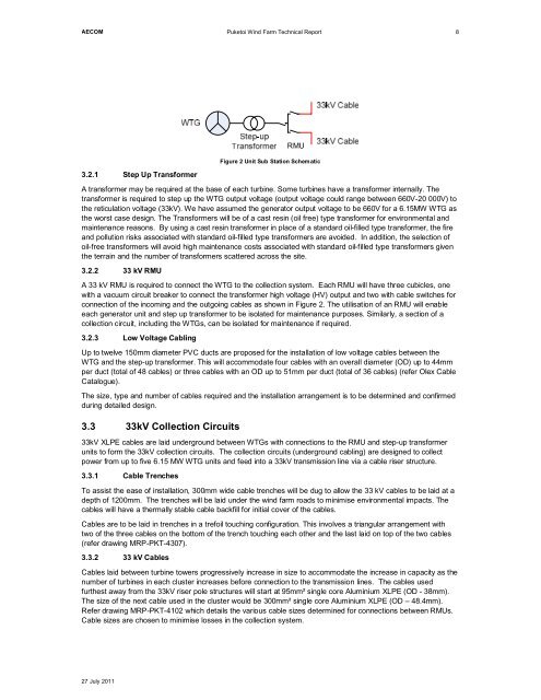
AECOMPuketoi Wind Farm Technical Report83.2.1 Step Up TransformerRMUFigure 2 Unit Sub Station SchematicA transformer may be required at the base of each turbine. Some turbines have a transformer internally. Thetransformer is required to step up the WTG output voltage (output voltage could range between 660V-20 000V) tothe reticulation voltage (33kV). We have assumed the generator output voltage to be 660V for a 6.15MW WTG asthe worst case design. The Transformers will be of a cast resin (oil free) type transformer for environmental andmaintenance reasons. By using a cast resin transformer in place of a standard oil-filled type transformer, the fireand pollution risks associated with standard oil-filled type transformers are avoided. In addition, the selection ofoil-free transformers will avoid high maintenance costs associated with standard oil-filled type transformers giventhe terrain and the number of transformers scattered across the site.3.2.2 33 kV RMUA 33 kV RMU is required to connect the WTG to the collection system. Each RMU will have three cubicles, onewith a vacuum circuit breaker to connect the transformer high voltage (HV) output and two with cable switches forconnection of the incoming and the outgoing cables as shown in Figure 2. The utilisation of an RMU will enableeach generator unit and step up transformer to be isolated for maintenance purposes. Similarly, a section of acollection circuit, including the WTGs, can be isolated for maintenance if required.3.2.3 Low Voltage CablingUp to twelve 150mm diameter PVC ducts are proposed for the installation of low voltage cables between theWTG and the step-up transformer. This will accommodate four cables with an overall diameter (OD) up to 44mmper duct (total of 48 cables) or three cables with an OD up to 51mm per duct (total of 36 cables) (refer Olex CableCatalogue).The size, type and number of cables required and the installation arrangement is to be determined and confirmedduring detailed design.3.3 33kV Collection Circuits33kV XLPE cables are laid underground between WTGs with connections to the RMU and step-up transformerunits to form the 33kV collection circuits. The collection circuits (underground cabling) are designed to collectpower from up to five 6.15 MW WTG units and feed into a 33kV transmission line via a cable riser structure.3.3.1 Cable TrenchesTo assist the ease of installation, 300mm wide cable trenches will be dug to allow the 33 kV cables to be laid at adepth of 1200mm. The trenches will be laid under the wind farm roads to minimise environmental impacts. Thecables will have a thermally stable cable backfill for initial cover of the cables.Cables are to be laid in trenches in a trefoil touching configuration. This involves a triangular arrangement withtwo of the three cables on the bottom of the trench touching each other and the last laid on top of the two cables(refer drawing MRP-PKT-4307).3.3.2 33 kV CablesCables laid between turbine towers progressively increase in size to accommodate the increase in capacity as thenumber of turbines in each cluster increases before connection to the transmission lines. The cables usedfurthest away from the 33kV riser pole structures will start at 95mm² single core Aluminium XLPE (OD - 38mm).The size of the next cable used in the cluster would be 300mm² single core Aluminium XLPE (OD – 48.4mm).Refer drawing MRP-PKT-4102 which details the various cable sizes determined for connections between RMUs.Cable sizes are chosen to minimise losses in the collection system.27 July 2011