GLOBE/ANGLE CAGE-GUIDED CONTROL VALVES - OME
GLOBE/ANGLE CAGE-GUIDED CONTROL VALVES - OME
GLOBE/ANGLE CAGE-GUIDED CONTROL VALVES - OME
- No tags were found...

You also want an ePaper? Increase the reach of your titles
YUMPU automatically turns print PDFs into web optimized ePapers that Google loves.
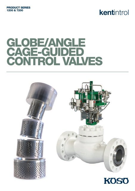
PRODUCT SERIES1200 & 7200kentintrol<strong>GLOBE</strong>/<strong>ANGLE</strong><strong>CAGE</strong>-<strong>GUIDED</strong><strong>CONTROL</strong> <strong>VALVES</strong>
06FIGURE 4. SELECTION OF TRIM ON CONTAMINATED SERVICESFIGURE 5. TRIM INCORPORATING SOLID TUNGSTENCARBIDE INSERT1004PRESSURE DROP (BAR)1015671 2 3 43210 0001 001 01 1 1 10NO. PART NAME STD MATERIAL% CONTAMINATION BY WEIGHT1 Base material2 Base material + stellite face3 Base material + full face4 Tungsten carbide or ceramicFigure 4 gives an indication of the trim material overlay/insertrequirements based on the operating pressure drop and the levelof contamination. Other factors that will influence the correctmaterial selection are flashing or the level of entrained gas thatwill come out of solution as the process pressure reduces.1 Upper guide 17/4 Ph st. st2 Lower guide 17/4 Ph st. st3 Lower guide Tungsten carbidecarbide insertincorporating seat4 Plug stem 17/4 Ph st. st5 Carbide plug head Tungsten carbide6 Upper plug retainer 17/4 Ph st. st7 Lower plug retainer 17/4 Ph st. stTUNGSTEN CARBIDE TRIM DESIGNFigure 5 illustrates a carbide trim design. This has beendeveloped over many years with essential design criteria,interferences etc, critical to the correct operation of the valve.There are also various grades of tungsten carbide which areselected around the specific design and depend on theprocess fluid being controlled.The carbide cage is retained within a metallic cartridge(‘brickstopper’) protecting it against impact from large debris.Figure 5 illustrates a standard control valve seat design.However, KKI also uses a patented seating design oncontaminated services. This design is known as an LCV trim,the name taken from the application it was first used on. TheLCV design keeps the throttling components away from thehigh-velocity erosive zones by directing the flow to specificsacrificial energy-dissipating elements. The trim can beprovided with or without a sacrificial plug nose.SEAT EXIT DIFFUSERIt is recommended practice to specify angle valve design onhigh-pressure drop flashing/contaminated services. However,if the installation requires a globe design then KKIrecommends the use of a seat exit diffuser.The diffuser is used to prevent the highvelocity fluid exiting the trim fromimpinging directly onto the bodywall. The diffuser handles theinitial impact of the processfluid and then breaks the fluidflow into small jets directedtowards the valve outlet.The diffuser is normallymanufactured from hardenedmaterials or stellite overlayedstainless steel to reduce the rate of erosion.
PRODUCT SERIES1200 & 720007MULTI-STAGE GUIDES, HFD, HFT & HFLThe multi-stage guides, HFD (High Friction Double), HFT (HighFriction Triple) are a design enhancement on the standard HFtrim. They are used in applications where noise or cavitationwould otherwise be a problem. If not properly controlled, highpressure drop liquid applications can severely damage thevalve. Figure 6 shows a cage that has suffered from severecavitation damage. It should be noted that this mechanism canoccur on relatively low pressure drops with the more conventionaltrims, for example contoured, ported trim designs.This significantly reduces the likelihood of cavitation, becausethe final stage of let down has a relatively small pressure dropand, with its low recovery characteristic, this minimises thepotential for cavitation. Figure 8 represents the differencebetween a single stage high-recovery trim, and a three-stagetrim with equal stage pressure drop, e.g. the HFL3 design.FIGURE 6. CAVITATION DAMAGEIn order to avoid the destructive effects of cavitation, it isnecessary to apportion the pressure drop across a number ofstages of let down. There are two different families of trimsthat can be applied to this problem, as well as the Series 50/57specialist anti-cavitation trim design and Vector (labyrinth). TheHFD (two stages) and HFT (three stages) apportion thepressure drop equally across either two or three stages of letdown. The stages are in the form of concentric sleeves, drilledwith radial holes within a number of grooves that form distinctflow galleries. These will be specified on the less severeapplications.The HFL design, illustrated in Figure 7, also incorporates anumber of concentric sleeves (two or more). Each sleeve has amultitude of grooves incorporating radial holes. The grooves ineach sleeve line up to create a torturous radial flow path (seeFigure 9). The trim uses the principle of controlled trim exitvelocity. The holes within the sleeves are completelymisaligned to produce a tortuous path through the trim.Energy is dissipated within the cage by the combined effect offlow splitting, flow impingement, and turning of the flow as itpasses through the sleeves. There is a large increase in flowarea between the stages of let down resulting in a reduction inpressure drop as the flow passes from one stage to the next.FIGURE 7. HFL-3 TRIM DESIGNFIGURE 8. STAGE PRESSURE DROPP1HFL-3 stagepressure dropStage 1P2PVP 1 VCHigh recoveryStage 2Stage 3CAVITATING FLOWVENA OUTLETValve inletValve outlet
08FIGURE 9. FLOW PATH THROUGH A LOW NOISE TRIM (HFL)Concentric sleeves fit over eachother to produce a ‘tortuous’path with no line of site andpressure drop control through100% of travel.Flow pathGAS SERVICE TRIM SELECTIONThe major factors to be considered in the selection of a valvetrim on a gas/vapour service are aerodynamic noise generation,vibration, and high fluid velocities. Each of these are interrelatedin that high velocities can lead to vibration and resultant noise,and will also generate aerodynamic noise. It is thereforenecessary to control the fluid velocity through the stages of letdown in the trim and also in the valve outlet and downstreampipework. Poor installation of pipework, such as bendsimmediately before and/or after the valve can also be a majorfactor in the valve functioning correctly.KKI undertook an extensive research programme during the1980s into aerodynamic noise generation within control valves.This resulted in the successful introduction of low-noise trimdesigns referred to as HFQ1 and HFQ2. These complementedthe already proven HFD and HFT trim designs that had beenpreviously used for low-noise applications. The trims work in asimilar principle to the liquid service designs, in that they splitthe flow up into a large number of radial jets, see Figure 9. Thepreferred flow direction is ‘under’ the plug, this enables theoptimum flow area increase as the flow passes through eachstage of the trim. The result is a very low trim exit velocity andvery high levels of noise attenuation.The flow geometry means that the process fluid enters thecage radially and passes through the subsequent sleeves in atortuous path resulting in high frictional and impingementlosses. Shock wave formation is controlled by jet impingementonto the sleeves, which has been shown to have a major(advantageous) bearing on the noise generation process. TheHFL trim as discussed on the previous page and depicted aboveincorporates the highest level of attenuation, and is specifiedon the most arduous dutiesSILENCERSIn solving the aerodynamic noise generation problem it must alsobe recognised that there is a need to control downstreamvelocities, otherwise high pipeline velocities can producesecondary noise which could be significantly higher than thatproduced by the valve trim. It is generally accepted that toachieve a low-noise solution, the downstream velocity shouldbe restricted to less than 0.3 times the fluid sonic velocity. Thiscoincides with the velocity at which compressibility effects startto become noticeable. In order to address this problem, KKIutilises downstream silencers in the form of a taper pipe fittedwith a number of baffle plates (circular plates with a number ofdrilled holes). These are used to produce a back-pressure to thevalve and are selected so that the velocity from the trim exit tothe valve outlet is less than 0.3 times sonic velocity (0.3 Mach).In selecting these devices it is necessary to ensure that the trimand silencer system operate effectively over the full range ofoperating conditions. This approach has effectively been used byKKI for more than 30 years. A large number of these units areinstalled in the oil and gas and power sectors.VARIABLE STAGE GUIDEThe variable stage guide is used on applications where multiplestages of pressure let down are required, but a high trimcapacity is desirable. The trim is therefore constructed withmultiple stages of pressure let down at lower travels, buttypically is a single stage trim at higher travels. This design issuitable for controlling high pressure drops at low flow ratesand a reduced pressure drop at normal or maximum flow rate.The number of stages of pressure let down and the actualtransition between the multiple and single guides is dependenton the process conditions, so each variable stage guide tendsto be designed specifically for the application.
PRODUCT SERIES1200 & 720009VECTOR TM SEVERESERVICE TRIMSKKI is now in the position to supply the KOSO Vector trims.These trims extend the capability of KKI to offer trim designsfor the most severe operating conditions now found in thevarious industries we serve. KKI is in the enviable position ofbeing able to supply the most appropriate design for thespecified application whether high pressure drop cavitating, highpressure drop flashing or high pressure drop gas applications.This proven trim design delivers accurate control, and long life,free from cavitation, erosion, vibration and noise problems.FIGURE 10. VECTOR D TRIM DESIGNThe design has evolved through many decades of experience insolving severe service applications where durability, reliability,repeatability and control precision are required. The advanceddesign velocity control trim prevents generation of noise and/orcavitation at the source. The typical applications for which theKOSO Vector trim has been applied also include compressorrecycle and turbine by-pass. KOSO Vector trim limits harmful flowvelocities by separating the flow into smaller individual channels,and staging the full pressure drop across multiple turns in the fluidpath. This is the basic principle of the HFL trim designs, however,on the Vector designs the allowed pressure drops are significantlylower, leading to much lower velocities that are well within anythreshold for erosion for the majority of trim materials.As well as the Vector D trim shown in Figure 10. KOSO has alsodeveloped Vector M trim, shown in Figure 11. This gives asmooth and continuous increasing flow along the entire strokelength. This eliminates the inherent stepped flow that occurs inmost stacked disc designs, see Figure 12.FIGURE 11. VECTOR M TRIM DESIGNFIGURE 12. FLOW CHARACTERISTIC COMPARISONBETWEEN D AND J VECTOR
10SELECTION GUIDELINESThe following tables are used during the selection process of the valve. Design Cvvalues are incorporated in globe/angle cage-guided valves technical data.Flanges are specified as a nominal size, the actual bore size varies with pressureclass. On higher rated flanges, the flange bore can be considerably less than thebody bore area. This could lead to the flange end connection restricting the capacityof the valve. In order to ensure this does not happen, the following tables referencethe end sizes available as a function of valve body size and pressure rating.TABLE 13. FLANGED END RESTRICTIONSVALVE BODY SIZEAVAILABLE END CONNECTION SIZEto ANSI ANSI ANSI ANSIin mm 600 900 1500 25001 25 1 1 1 11 1 /2 40 1 1 /2 1 1 /2, 2, 1 1 /2, 2, 3 2, 32 50 2 2, 3, 2, 3, 4 3, 43 80 3 3, 4, 3, 4, 6 4, 64 100 4 4, 6, 6, 8 6, 86 150 6 6, 8, 8, 10 8, 108 200 8 8, 10, 10, 12 12, 1410 250 10 10, 12, 12, 14 14, 1612 300 12 12, 14, 14, 16 18, 2014 350 14 16, 18, 16, 1816 400 16 18, 20, 20, 2418 450 1820 500 2024 600 24TABLE 14. BUTT WELD END RESTRICTIONSVALVE BODY SIZEAVAILABLE END CONNECTION SIZEto ANSI ANSI ANSI ANSIin mm 600 900 1500 25001 25 1 1 1 11 1 /2 40 1 1 /2, 2, 3 1 1 /2, 2, 3 1 1 /2, 2, 3 1 1 /2, 2, 3, 42 50 2, 3, 4 2, 3, 4, 2, 3, 4 2, 3, 4, 63 80 3, 4, 6 3, 4, 6 3, 4, 6 4, 6, 84 100 4, 6, 8 4, 6, 8 8, 10 6, 8, 106 150 6, 8, 10 6, 8, 10 8, 10, 12 8, 10, 128 200 8, 10, 12 8, 10, 12 10, 12, 14 12, 14, 1610 250 10, 12, 14 10, 12, 1412 300 12, 14, 16 12, 14, 1614 350 14, 16, 18 16, 18, 2016 400 16, 18, 20 20, 24
PRODUCT SERIES1200 & 720011TABLE 15. BONNET/PACKAGING OPTIONSBELOW -100 O C -100 O C TO -29 O C -29 O C TO -250 O C -250 O C TO -400 O C ABOVE 400 O CCOMPONENT (-150 O F) (-148 O F TO -4 O F) (-4 O F TO 482 O F) (482 O F TO 752 O F) (752 O F)BONNET CRYOGENIC NORMALISING STANDARD NORMALISING NORMALISINGPACKINGS PTFE CHEVRON PTFE CHEVRON PTFE CHEVRON GRAPHITE(*) GRAPHITE(*)NOTE: * Not suitable for oxidizing service. The Envirograph range of packings, Envirograph 4 to 6 area used for low emission requirements and a graphite based packing system.TABLE 16. PRESSURE DROP LIMITATIONSLIQUIDSGASES/VAPOURSMAX ∆ PMAX ∆ PTRIM DESIGN FLOW DIR. (BAR) (BAR)HF UNDER 10 75*OVER 50* 100HFD UNDER 20 150*OVER 95* 150HFT UNDER 30 180*OVER 125* 180HF4 OVER 185 -HF5 OVER 230 -HFQ1 UNDER - 150HFQ2 UNDER - 180HFL – 2 UNDER 80 150HFL – 3 UNDER 125 180HFL – 4 UNDER 140 210HFL – 5 UNDER 190 230NOTE: 1. Pressure drop limits do not apply to flashing applications.2. These apply on the basis that cavitation has been eliminated.3. In cases of wet/saturated vapours then pressure drops for liquids should be applied.4. On liquid applications, where final stage pressure drops are greater than 50bar, angle valves are recommended.5. VECTOR TM velocity control labyrinth multi-turn disk stack trim is available for high pressure drop applications.* These are the recommended flow directions for these trims.VECTOR FOR HIGH RANGEABILITY APPLICATIONSPACKING ARRANGEMENTS
12TABLE 17. STANDARD RANGEABILITY <strong>VALVES</strong>TRIM SIZE HF SINGLE STAGE MULTI-STAGE DESIGNREF - in STANDARD RANGEABILITY STANDARD RANGEABILITY1/4 TO 1/2 20: 1 15: 13/4 TO 1 30: 1 25: 111/2 TO 2 40: 1 35: 13 TO 6 50: 1 45: 18 TO 12 60: 1 55: 114 TO 24 70: 1 60: 1ABOVE 24 80: 1 70: 1NOTE: Rangeability is the relationship between the minimum controllable Cv and the design Cv of the trim.TABLE 24. SERIES 1200 & 7200 GAS VAPOUR VELOCITY LIMITSINLETOUTLETVALVE SIZE REQ. NOISE LEVEL dBA ft/s m/s ft/s m/s MACH NUMBERALL > 95 670 204 1150 350 0.65ALL < 95 670 204 1150 350 0.51/2" TO 2" < 85 670 204 1150 350 0.43" TO 24" < 85 670 204 1150 350 0.3NOTE: Use velocity limit as higher of linear velocity or Mach numbers.<strong>CONTROL</strong> <strong>VALVES</strong> USED ON VENTTO FLARE APPLICATIONS
PRODUCT SERIES1200 & 720013TABLE 18. STANDARD MATERIAL COMBINATIONSINDUSTRY TYPICAL DUTIES GUIDE PLUG STEM SEAT TEMPSECTORRANGEOIL Standard 316 st. st. + hard 316 st. st. 316 st. st. Integral with guide/ -40 O C to 250 O C& GAS combination/NACE chrome plated or or 17-4PH st. st. 316 st. st.17/4 PH St.St.Sea water/sour gas Duplex + hard Duplex Duplex Integral with guide/ -40 O C to 250 O Cchrome platedDuplex st. st.Sea water/sour gas Super Duplex + Super Duplex Super Duplex Integral with guide/ -40 O C to 250 O Chard chromeSuper Duplex st. st.platedHighly corrosive Monel K500 Monel 400 Monel K500 Integral with guide/ -40 O C to 250 O Chardened Monel K 500;Highly corrosive Hastelloy (B/C) + Hastelloy (B/C) Hastelloy (B/C) Integral with guide/ -40 O C to 250 O Chard chrome platedHastelloy (B/C)Highly corrosive Alloy 625 + hard Alloy 625 Alloy 625 Integral with guide/ -40 O C to 250 O Cchrome plated alloy 625Highly corrosive Titanium/titanium Titanium Titanium Integral with guide/ -40 O C to 250 O CnitridetitaniumLow temp Hard chrome plate Gr. 6 Stellite - - -100 O C to 250 O CCryogenic Gr. 6 Stellite Gr. 6 Stellite - - 1.75” (45mm)/secLiquids – pressure - Gr. 6 Stellite - Gr. 6 Stellite -drops 20 - 35bar(300 - 500psi)Liquids – pressure Gr. 6 Stellite Gr. 6 Stellite - Gr. 6 Stellite -drops 35bar(500psi)Liquids – pressure Tungsten carbide Tungsten carbide - Tungsten carbide -drops > 150bar insert insert insert(2175psi)Contaminated Tungsten carbide Tungsten carbide - Tungsten carbide -services insert insert insertPOWER Feadwater 420 St. St 420 St.St. Rc 35- 431 st. st. Integral with guide/ 64 stellited 316 st. st./ 316 st. st.+ stelliteNOTE: Materials listed above are suitable for most applications. Material variations are available on request. Tungsten carbide/ceramic are available for high duty process applications.TABLE 19. LEAKAGE CLASS OPTIONSPLUG DESIGN SEATING STYLE PISTON RING LEAKAGE CLASS TEMPERATURE RANGEUnbalanced Metal/metal None III, IV &V Cryogenic to 565 o CUnbalanced Metal/soft face None VI Cryogenic to 315 o CBalanced Metal/metal Graphite III 250 o C to 565 o CBalanced Metal/metal Carbon/PTFE IV & V Cryogenic to 265 o CBalanced Metal/metal Alloy 25 IV 265 o C to 565 o CPilot balanced Metal/metal Carbon V 265 o C to 565 o CBalanced Metal/soft face Carbon/PTFE VI* Cryogenic to 265 o CNOTE: For contaminated services a scraper will be incorporated within the plug seal. * This is a special design for valve sizes upto 10” (250mm)– the application must be reviewed by Applications before specifying.
14SERIES 12SERIES 72TABLE 20. SERIES 1200 & 7200 COMMON DIMENSIONS1/2” 1/4” 1” 1 1/2” 2” 3” 4” 6” 8” 10” 12” 14” 16” 18” 20” 24”15mm 20mm 25mm 40mm 50mm 80mm 100mm 150mm 200mm 250mm 300mm 350mm 400mm 450mm 500mm 600mmANSI 150 AND F 4 1 /4 7 1 /4 7 1 /4 8 3 /4 10 11 3 /4 13 7 /8 17 3 /4 21 3 /8 26 1 /2 29 35 40 45 3 /8 52 1 /2 58 1 /4PN10 & 16 184 184 184 222 254 298 352 451 543 673 737 889 1016 1153 1334 1480ANSI 300 F 7 1 /2 7 1 /2 7 3 /4 9 1 /4 10 1 /2 12 1 /2 14 1 /2 18 5 /8 2 3 /8 27 7 /3 30 1 /2 36 1 /2 41 5 /8 47 54 60PN 25 & 40 191 191 197 235 267 218 368 473 568 708 775 927 1057 1194 1372 1524ANSI 600 PN 100 F 8 8 1 /8 8 1 /4 9 7 /8 11 1 /4 13 1 /4 15 1 /2 20 24 29 5 /8 32 1 /4 38 1 /4 43 5 /8 49 1 /4 60 63203 203 210 251 286 3337 394 508 610 752 819 972 1108 1251 1524 1600TO ANSI 600 M 2 5 /8 3 1 /4 3 1 /2 4 3 /8 5 5 /8 8 8 3 /4 10 12 1 /2 13 15 3 /4 14 1 /4 19 1 /4 18 1 /467 82 89 318 143 203 222 254 318 330 400 362 489 464STANDARD BONNET L 5 3 /4 5 3 /4 5 3 /4 8 1 /8 7 3 /8 9 7 /8 11 13 1 /8 15 3 /4 17 7 /8 20 1 /2 24 1 /2 28 3 /8 28 1 /8 35 1 /2 34SERIES 12/72 TO 146 146 146 206 187 251 279 333 400 454 521 622 721 714 902 864ANSI 600NORMALISING L 8 3 /4 8 3 /4 8 3 /4 12 1 /8 12 3 /8 15 1 /8 16 5 /8 18 7 /8 21 3 /4 26 7 /8 30 1 /2 35 3 /2 29 7 /8 40 1 /6 42 5 /8 46 1 /2BONNET SERIES 222 222 222 308 314 384 422 479 552 683 775 908 1013 1020 1082 118012/72 TO ANSI 600STANDARD BONNETSERIES 12/72NORMALISINGBONNET SERIES 12/72LLVALVE STROKE 1 1 /8 1 1 /8 1 1 /8 1 1 /8 1 1 /2 2 1 /4 2 1 /4 3 1 /2 4 5 6 7 8 9 10 1228 28 28 28 38 57 57 89 102 127 152 178 203 229 254 305BONNET MOUNT DIA L 2 1 /8 2 1 /8 2 1 /8 2 1 /8 2 1 /8 2 13 /16 2 13 /16 3 9 /16 3 9 /16 3 9 /16 39/16 5 3 /4 5 3 /4 5 3 /4 5 3 /4 5 3 /4( TO ANSI 600) 54 54 54 54 54 71 71 90 90 90 90 146 146 146 146 146BONNET MOUNT DIA L 2 1 /8 2 1 /8 2 1 /8 2 1 /8 2 1 /8 21 3 /16 21 3 /16 3 9 /16 3 9 /16 5 3 /4 5 3 /4 5 3 /4 5 3 /4 5 3 /4 5 3 /4 5 3 /4ANSI 900/1500 54 54 54 54 54 71 71 90 90 146 146 146 146 146 146 146BONNET MOUNT DIA L 2 1 /8 2 1 /8 2 1 /8 2 13 /16 2 13 /16 2 13 /16 3 9 /16 3 9 /15 3 9 /16 5 3 /4 5 3 /4 5 3 /4 5 3 /4 5 3 /4 5 3 /4 5 3 /4ANSI 2500 54 54 54 71 71 71 90 90 90 146 146 146 146 146 146 146TABLE 21. SERIES 7200 DIMENSIONS1/2” 1/4” 1” 1 1/2” 2” 3” 4” 6” 8” 10” 12” 14” 16” 18” 20” 24”15mm 20mm 25mm 40mm 50mm 80mm 100mm 150mm 200mm 250mm 300mm 350mm 400mm 450mm 500mm 600mmANSI 150 AND F 4 3 /8 5 5 7 /8 61 5 /16 8 7 /8 10 11 /16 13 1 /4 14 1 /2 17 1 /2 20 22 11 /16 26 1 /4 29 1 /8PN10 & 16 111 127 148 352 225 271 337 368 889 508 576 667 740ANSI 300 F 4 5 /8 5 1 /4 6 1 /4 7 1 /4 9 5 /16 11 3 /16 13 15 /16 15 1 /4 18 1 /4 20 13 /16 23 1 /2 27 30PN 25 & 40 117 267 159 184 237 284 354 387 464 529 597 686 762ANSI 600 PN 100 F 4 5 /16 5 5 /8 6 5 /8 7 3 /4 10 12 14 15 /16 16 1 /8 19 1 /8 21 13 /16 24 5 /8 28 1 /2 31 1 /2125 163 168 197 254 305 376 410 486 5548 625 724 800
KOSO KENT INTROL LIMITEDARMYTAGE ROADBRIGHOUSEWEST YORKSHIREHD6 1QFUKTELEPHONE+44 (0)1484 710311FACSIMILE+44 (0)1484 407407EMAILinfo@kentintrol.comWEBSITEWWW.KENTINTROL.COMKoso Kent Introl Limited is part of the KOSO Group of companies.The Company’s policy is one of continuous development and the right isreserved to modify the specifications contained herein without notice.Copyright © July 2010All rights reserved Koso Kent Introl Limited