Mechanical Design of the LMDE.pdf - Heroicrelics
Mechanical Design of the LMDE.pdf - Heroicrelics
Mechanical Design of the LMDE.pdf - Heroicrelics
- No tags were found...

Create successful ePaper yourself
Turn your PDF publications into a flip-book with our unique Google optimized e-Paper software.
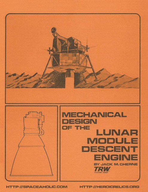
MECHANICALDESIGNDFTHE LUNARMODULEDESCENTENGINEBY .JACK M . CHERNETRW.n¥"M$ C_HTTP'I/SPACEAHOL.IC.COMHTTP://HERCICRELlCS.CRG
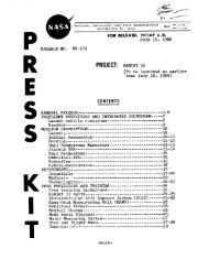
MECHANICAL DESIGN OF THELUNAR MODULE DESCENT ENGINEby Jack M. CherneManager, Engineering <strong>Design</strong> DepartmentPower Systems DivisionTRW SystemsRedondo Beach, California, U.S.A.IntroductionTo land astronauts on <strong>the</strong> moon, <strong>the</strong> Lunar Module must descend froma lunar orbit to a hovering position above <strong>the</strong> surface <strong>of</strong> <strong>the</strong> moon, select asite and descend to a s<strong>of</strong>t landing. TRW Systems has translated <strong>the</strong>se propulsionrequirements into <strong>the</strong> Lunar Module Descent Engine (<strong>LMDE</strong>).The <strong>LMDE</strong> is a pressure-fed, bipropellant, variable thrust, gimballing,chemical rocket engine with a maximum thrust <strong>of</strong> 9850 lbs, throttleabledown to approximately 1000 lbs . The throttling is obtained by means <strong>of</strong>dual , variable area, cavitating venturi flow control valves mechanicallylinked to a variable area injector. Ignition is hypergolic in <strong>the</strong> combustionchamber since <strong>the</strong> propellants are nitrogen tetroxide (N 0 ) and aZ 450-50 mixture <strong>of</strong> hydrazine (N H ) and unsymmetrical dimethylhydrazine (UDMH).Z 4Figure 1.Lunar Module DescentEngineThe time available for developingand qualifying <strong>the</strong> <strong>LMDE</strong> formanned flight was short. To assurethat unforeseen problems did notdevelop during <strong>the</strong> latter part <strong>of</strong> <strong>the</strong>development and qualification phase,it was important to plan an adequatecomponent test program early in <strong>the</strong>engine's development. This programincluded tests <strong>of</strong> details and subassembliesto locate weaknesses in <strong>the</strong>design. Upon correction <strong>of</strong> <strong>the</strong>sedeficiencies, <strong>the</strong> next level <strong>of</strong> assemblywas tested. Then, step by stepassurance was developed that <strong>the</strong> completeengine performed as required.Details <strong>of</strong> <strong>the</strong> mechanical design <strong>of</strong><strong>the</strong> <strong>LMDE</strong> (Figure 1) are describedlater in <strong>the</strong> paper. All aspects <strong>of</strong><strong>the</strong> design, including discussion <strong>of</strong><strong>the</strong> critical environments and <strong>the</strong>development problems anticipated, arepresented along with <strong>the</strong> componenttests used to find <strong>the</strong> solutions to<strong>the</strong>se problems.- 1 -
Engine DescriptionCOMffNSAT1NGSPItiNGFigure 2.The <strong>LMDE</strong> is a compact packageweighing 394 lbs and having overalldimensions <strong>of</strong> 90-1/2 inches by 59 inchesdiameter. Interface with <strong>the</strong> LunarModule vehicle is made at two trunnionsthrough <strong>the</strong> gimbal frame, providingcapability <strong>of</strong> gimballing 6° in bothlateral directions (Figure 2). Propellantsare supplied to <strong>the</strong> <strong>LMDE</strong>through two stainless steel propellantinlet lines with a simple bolted flangeinterface joint. The inlet linesaccommodate <strong>the</strong> 6° <strong>of</strong> gimbal motion bymeans <strong>of</strong> a pair <strong>of</strong> flexible bellowswelded in <strong>the</strong> lines at <strong>the</strong>ir intersectionwith <strong>the</strong> gimbal axes. Propellantsflow from <strong>the</strong> lines through<strong>the</strong> cavitating venturi flow controlvalves to <strong>the</strong> quad-redundant ball shut<strong>of</strong>fvalves. From <strong>the</strong> shut<strong>of</strong>f valve,<strong>the</strong> fuel enters <strong>the</strong> manifold <strong>of</strong> <strong>the</strong>head end. The major percentage <strong>of</strong><strong>the</strong> fuel is injected axially into <strong>the</strong>combustion chamber through <strong>the</strong> annularorifice <strong>of</strong> <strong>the</strong> variable area concentricinjector, while <strong>the</strong> remainder is distributedto <strong>the</strong> 36 ports <strong>of</strong> <strong>the</strong> barriercooling ring where it is injected along<strong>the</strong> wall <strong>of</strong> <strong>the</strong> chamber. The oxidizerenters <strong>the</strong> center <strong>of</strong> <strong>the</strong> injectorassembly, flows down and is directedinto <strong>the</strong> combustion chamber radiallythrough <strong>the</strong> variable area ports in ahorizontal disc composed <strong>of</strong> 36 jetswhich impinge on and ignite with <strong>the</strong>sheet <strong>of</strong> fuel.Figure 3.I flOW"'''LYE.!l!!!Thrust Control AssemblyThrust control is accomplishedby adjusting <strong>the</strong> propellant flow ratesand varying <strong>the</strong> area <strong>of</strong> <strong>the</strong> injectionports to maintain near uniform velocities.Electrical control signals from<strong>the</strong> Lunar Module are received by <strong>the</strong>electromechanical throttle actuatorwhich converts <strong>the</strong> signal to a linearposition <strong>of</strong> <strong>the</strong> actuator screw jack(Figure 3). Attached to <strong>the</strong> top <strong>of</strong><strong>the</strong> screw jack is a cross beam. Theright side <strong>of</strong> <strong>the</strong> cross beam is connecteddirectly to <strong>the</strong> oxidizer flowcontrol valve through a flexural element.The left side <strong>of</strong> <strong>the</strong> cross beam- 2 -
is connected to <strong>the</strong> fuel flow control valve through <strong>the</strong> mixture ratio trimlinkage, establishing <strong>the</strong> desired motion <strong>of</strong> <strong>the</strong> fuel flow control valve relativeto <strong>the</strong> motion <strong>of</strong> <strong>the</strong> oxidizer flow control valve. This produces <strong>the</strong>required mixture ratio <strong>of</strong> <strong>the</strong> propellants. This linkage permits adjustment<strong>of</strong> <strong>the</strong> mixture ratio during acceptance tests <strong>of</strong> <strong>the</strong> engine. Also attachedto <strong>the</strong> cross arm by means <strong>of</strong> two flexures is a walking beam, pivoted <strong>of</strong>f <strong>the</strong>manifold assembly, which translates motion from <strong>the</strong> throttle actuator assemblyto <strong>the</strong> injector assembly. Motion <strong>of</strong> <strong>the</strong> movable sleeve in <strong>the</strong> injectorsimultaneously changes <strong>the</strong> gap in <strong>the</strong> fuel orifice and <strong>the</strong> size <strong>of</strong> <strong>the</strong>ports in <strong>the</strong> oxidizer outlets.The manifold assembly which provides <strong>the</strong> mounting points for <strong>the</strong>throttle mechanism is <strong>the</strong> distribution network for <strong>the</strong> propellants and <strong>the</strong>end closure <strong>of</strong> <strong>the</strong> combustion chamber. A welded titanium shell which boltsto <strong>the</strong> manifold forms <strong>the</strong> structural element <strong>of</strong> <strong>the</strong> combustion chamber and<strong>the</strong> throat <strong>of</strong> <strong>the</strong> engine. The phenolic-fiberglass ablative liner provides<strong>the</strong> <strong>the</strong>rmal barrier between <strong>the</strong> burning propellants and <strong>the</strong> structural case.Attachments are provided in <strong>the</strong> throat area for <strong>the</strong> gimbal assembly. Thechamber and ablative liner extend to <strong>the</strong> 16:1 area ratio point where aflanged joint provides for attachment <strong>of</strong> <strong>the</strong> nozzle extension.The nozzle extension is a radiation-cooled, bell-shaped cone whichprovides for expansion <strong>of</strong> <strong>the</strong> gases from <strong>the</strong> 16:1 area ratio at <strong>the</strong> attachmentto <strong>the</strong> combustion chamber to <strong>the</strong> 47.5:1 area ratio exit.The total firing time requirement for <strong>the</strong> LM Descent Engine is1000 seconds. This is composed <strong>of</strong> 90 seconds <strong>of</strong> acceptance testing plus910 seconds <strong>of</strong> duty cycle. A nominal duty cycle is shown in Figure 4.Temperature <strong>of</strong> <strong>the</strong> titanium combustion chamber case does not exceed 800°Fduring duty cycle firing.Thermal requirements for <strong>the</strong> Lunar Module require that <strong>the</strong> externaltemperature around <strong>the</strong> engine above <strong>the</strong> nozzle extension remain below400°F during <strong>the</strong> duty cycle firing. This is accomplished by <strong>the</strong> use <strong>of</strong> acomposite stainless steel and fiberglass insulating blanket around <strong>the</strong>combustion chamber.12,OOOr-= __ ~'-""----"-------""----,,,,,,,---,ORBIT INJECTION I10,0008,000 .THRUSTL66,0004,0002..000'(I~;' :=;:!~ I ·1-1 ~"'M_ jt-- I ---+--1 ~I i IDESCENT ENGINE STARTSAND VEHICLE STABlUZATIONI+---' LANDi°O~~~-'~N\-~-~~~~~~-~~~~~~Figure 4.- 3 -
Engine GimbalThe gimbal assembly is a rectangular frame composed <strong>of</strong> four beamswith a modified I section machined out <strong>of</strong> 7075-T73 aluminum alloy. Theflanges <strong>of</strong> <strong>the</strong> beams are tapered in thickness and planform for minimumweight. A trunnion attaches to <strong>the</strong> center <strong>of</strong> each beam through a sphericalFabroid bearing. One pair <strong>of</strong> trunnions mounts to <strong>the</strong> engine thrust chamberand <strong>the</strong> o<strong>the</strong>r pair mounts to <strong>the</strong> Lunar Module support truss (Figure 5) .Figure 5.Thirteen load conditions were defined as applicable to <strong>the</strong> gimbalframe. These included pre-launch shock, launch and boost vibration, enginestart, lunar descent and lunar landing. Preliminary structural analysisindicated that seven <strong>of</strong> <strong>the</strong>se were critical. Thermal analyses provided amaximum temperature in <strong>the</strong> gimbal beams <strong>of</strong> 200°F at <strong>the</strong> end <strong>of</strong> <strong>the</strong> mission .Ultimate static and sinusoidal load factors <strong>of</strong> 1.5 were used. An ultimateload factor <strong>of</strong> 2.25 was applied to random vibration environments.Prior to <strong>the</strong> tests <strong>of</strong> <strong>the</strong> complete engine in <strong>the</strong> gimbal frame fordynamic environment, several component tests were conducted to ensure that<strong>the</strong>se components would survive <strong>the</strong>ir load and life requirements.After <strong>the</strong> selection <strong>of</strong> <strong>the</strong> configuration <strong>of</strong> <strong>the</strong> gimbal, two testprograms were initiated and completed successfully before <strong>the</strong> total systemtests were started. These were a static structural test to destruction <strong>of</strong>one side <strong>of</strong> <strong>the</strong> gimbal frame and a series <strong>of</strong> life cycle tests on individualgimbal bearings for shock, cyclic rotation and vibration.Since <strong>the</strong> aluminum gimbal frame was designed for m1n1mum weight ,<strong>the</strong> static test <strong>of</strong> <strong>the</strong> single side beam was used to substantiate <strong>the</strong> stressanalysis <strong>of</strong> <strong>the</strong> tapered flange members. Subjecting an individual Fabroidbearing to <strong>the</strong> cyclic rotations experienced during gimballing <strong>of</strong> <strong>the</strong> engine- 4 -
during lunar descent, in addition to <strong>the</strong> shock and vibration environment <strong>of</strong>launch and boost and engine firing, revealed <strong>the</strong> need to make some changesto <strong>the</strong> bearing design. Those changes were accomplished before tests <strong>of</strong> afull gimbal frame was scheduled to start.When a complete gimbal assembly was available for fur<strong>the</strong>r testing,an engine assembly still could not be used; <strong>the</strong>refore, it was planned touse an engine mass simulator. This unit simulated <strong>the</strong> mass properties in<strong>the</strong> Y and Z axes but not in <strong>the</strong> X axis (<strong>the</strong> centerline <strong>of</strong> <strong>the</strong> engine thrust) .The gimbal was first subjected to <strong>the</strong> environments <strong>of</strong> salt fog,sand and dust and a limit load test to several <strong>of</strong> <strong>the</strong> critical loads. Abreakaway torque test on <strong>the</strong> bearings while subjected to a thrust load <strong>of</strong>10 , 500 lbs was used as one criteria for acceptance <strong>of</strong> <strong>the</strong> gimbal after eachtest. Alignment <strong>of</strong> <strong>the</strong> thrust axis was ano<strong>the</strong>r criteria.Shock tests <strong>of</strong> <strong>the</strong> gimbal with <strong>the</strong> engine mass simulator wereconducted about all three axes . A shock impulse <strong>of</strong> 15 g peak with a6 millisecond rise time was applied three times along each axis. During<strong>the</strong> shock test <strong>the</strong> gimbal was rigidly attached to <strong>the</strong> shock test equipment.No unexpected responses were noted.Vibration tests <strong>of</strong> <strong>the</strong> gimbal frame were next performed. Forthis test <strong>the</strong> gimbal trunnions were mounted to a structure which simulated<strong>the</strong> influence coefficients <strong>of</strong> <strong>the</strong> Lunar Module support structure. SeeFigures 6 and 7. During <strong>the</strong> first sinusoidal vibration sweep along <strong>the</strong>Y axis an unexpected torsional mode was observed at 18 cps. Strain gageswere installed on <strong>the</strong> gimbal frame to measure bending stresses due to <strong>the</strong>torsion and <strong>the</strong> survey repeated . As a result <strong>of</strong> <strong>the</strong> data obtained, itbecame apparent that it was necessary to correctly simulate <strong>the</strong> moment <strong>of</strong>inertia <strong>of</strong> <strong>the</strong> engine mass simulator about <strong>the</strong> X axis. The first simulation<strong>of</strong> I was 34 , 000 lb-in 2 while <strong>the</strong> calculated engine inertia wasxx66,000 lb-in 2 . The change in inertia was made and <strong>the</strong> vibration test completed.These tests pointed out a minor structural weakness which wouldhave delayed <strong>the</strong> qualification tests if not discovered at this time. Thebolt which attached <strong>the</strong> bearing to <strong>the</strong> gimbal frame was restrained againstrotation by means <strong>of</strong> two cotter pins. These pins failed in shear permitting<strong>the</strong> bolt to rotate during vibration. Retention <strong>of</strong> <strong>the</strong> bolt waschanged to <strong>the</strong> heat treated, machined lock ring shown in Figure 8.This specimen was <strong>the</strong>n subjected to mechanical cycling <strong>of</strong> ± 6 0for 500 cycles about each <strong>of</strong> <strong>the</strong> rotational axes while subjected to10,500 lbs <strong>of</strong> thrust load.Upon completion <strong>of</strong> <strong>the</strong> mechanical cycling test, a static test toultimate loads was performed for <strong>the</strong> most critical load conditions. Thenload was applied until failure for <strong>the</strong> most critical condition with thrustapplied at 6 0 in both directions from center . Failure occurred at39,800 lbs which is 1.92 times <strong>the</strong> ultimate load taking account for gimballedangle, <strong>the</strong>rmal degradation and o<strong>the</strong>r structural loads. SeeFigure 9.- 5 -
Figure 6.Engine Mass SimulatorMounted in GimbalFrame on VibrationTest FixtureFigure 7.View <strong>of</strong> Simulation<strong>of</strong> Lunar ModuleSupport StructureFigure 8 .Redesigned Bearing BoltRetention on Gimbal Frame- 6 -
Figure 9.Gimbal Fr ame Static Test SpecimenStress levels in <strong>the</strong> gimbal frame which were higher than anticipatedduring analysis due to <strong>the</strong> unexpected torsional mode aroused concernover <strong>the</strong> fatigue str ength <strong>of</strong> <strong>the</strong> assembly. The subject test specimen wasexposed to eleven times as many sinusoidal vibration cycles in <strong>the</strong> frequencyrange <strong>of</strong> 5 to 100 cps as is required for qualification. In addition, <strong>the</strong>exposure to random vibr ation was more than six times that required forqualification. Since <strong>the</strong> specimen withstood almost twice <strong>the</strong> ultimateload after experiencing all <strong>of</strong> this dynamic environment , confidence in itsability to perform during a lunar mission was established.As a result <strong>of</strong> <strong>the</strong> knowledge gained during <strong>the</strong> early componenttests and <strong>the</strong> gimbal frame tests with <strong>the</strong> engine mass simulator inOctober 1965, <strong>the</strong> gimbal on <strong>the</strong> design verification test <strong>of</strong> <strong>the</strong> completeengine in April 1966 and on <strong>the</strong> vibration test <strong>of</strong> <strong>the</strong> qualification enginein October 1966 performed without incident .Combustion ChamberThe combustion chamber consists <strong>of</strong> an ablative-lined titaniumalloy case to <strong>the</strong> 16 : 1 area ratio . Fabrication <strong>of</strong> <strong>the</strong> 6Al-4V alloytitanium case is accomplished by machining <strong>the</strong> chamber portion and <strong>the</strong> exitcone portion from forgings and welding <strong>the</strong>m into one unit at <strong>the</strong> throatcenterline. Thickness <strong>of</strong> <strong>the</strong> shell is a uniform 0 . 035 inch except at <strong>the</strong>upper end where <strong>the</strong> head end bolts on, at <strong>the</strong> weld joint and at <strong>the</strong> lowerflange where <strong>the</strong> nozzle extension attaches. On ei<strong>the</strong>r side <strong>of</strong> <strong>the</strong> throata pair <strong>of</strong> flanges are provided integral with <strong>the</strong> case for attachment <strong>of</strong>Z-shaped aluminum rings . These rings form <strong>the</strong> structural members forattachment <strong>of</strong> <strong>the</strong> gimbal trunnions . See Figure 10.Since <strong>the</strong> titanium chamber is one piece, <strong>the</strong> ablative liner isfabricated in two segments and installed from ei<strong>the</strong>r end . A metal lockingelement positively locks both halves <strong>of</strong> <strong>the</strong> liner toge<strong>the</strong>r as <strong>the</strong>y are installed.This lock is redundant since <strong>the</strong> shape <strong>of</strong> <strong>the</strong> nozzle extension- 7 -
Figure 10.Combustion Chamber Assemblyis such that <strong>the</strong> ablative liner is retained in <strong>the</strong> exit cone during transportationand launch and boost. During engine firing, thrust loads force<strong>the</strong> exit cone liner against <strong>the</strong> case.The titanium head end assembly attaches to <strong>the</strong> combustion chamberwith thirty-six A-286 steel 1/4 inch bolts. This joint also permits <strong>the</strong>transfer <strong>of</strong> moments around <strong>the</strong> corner insuring a continuous pressure vessel.In order to keep <strong>the</strong> maximum operating temperatures <strong>of</strong> <strong>the</strong> titaniumcase in <strong>the</strong> vicinity <strong>of</strong> 800°F, <strong>the</strong> ablative liner was designed as acomposite material providing <strong>the</strong> maximum heat sink at minimum weight. Theselected configuration consists <strong>of</strong> a high density, erosion-resistant silicacloth/phenolic material surrounded by a lightweight needle-felted silicamat/phenolic insulation.Temperature <strong>of</strong> <strong>the</strong> area around <strong>the</strong> combustion chamber is maintainedbelow 400°F with <strong>the</strong> aid <strong>of</strong> a heat shield attached to <strong>the</strong> outside<strong>of</strong> <strong>the</strong> titanium case. The heat shield consists <strong>of</strong> two layers <strong>of</strong>0.0015 inch stainless steel foil separated by fiberglass wool.Structurally, <strong>the</strong> ablative liner is not required to be loadcarrying in <strong>the</strong> pressure vessel. The maximum internal pressure is 116 psiwith an ultimate load factor <strong>of</strong> 3.0. Figure 11 presents <strong>the</strong> variation <strong>of</strong>chamber pressure at full thrust and shell temperature with distance along<strong>the</strong> combustion chamber used for design analysis.To analyze <strong>the</strong> chamber shell and head end assembly for <strong>the</strong> structuralloads applied, it was necessary to utilize a TRW digital computerprogram developed to perform static and dynamic analysis <strong>of</strong> axisymmetricthin shells <strong>of</strong> revolution subjected to arbitrary loads. Static and dynamicresponse <strong>of</strong> complex multi-segment shell assemblies are calculated. Loads,- 8 -
including temperature effects, <strong>of</strong> arbitrary meridional and circumferentialvariation, are computed - <strong>the</strong> latter by expansion in a Fourier series <strong>of</strong>harmonics. Orthotropic material properties, variable stiffness in <strong>the</strong>meridional direction, discrete circumferential stiffeners, and all physicallypossible boundary conditions are included.~,ov~TEMPfRATURE AND PRESSURE120I:~I:2000V,/'00MIIU8TI0N~ V~ --'IIfO'T"" 7'0I1AMI!fft f'ftES8URf ~~ ~~8I£Ll. TBIf'fIIAllJIIf.\\ ' /f-,V-I~lOOil!J900M"/OOiti"- 1=4 1Z 18 20 Z4 Z8 3Z 36 '10 44ClIWI!BI LB«mI - INCHSFigure 11.The solution is based on Fltigge's shell equations, which arereduced to four second-order partial differential equations in terms <strong>of</strong><strong>the</strong> components <strong>of</strong> displacement and <strong>the</strong> meridional moment.Substantiation <strong>of</strong> <strong>the</strong> structural integrity <strong>of</strong> <strong>the</strong> combustionchamber and head end assembly was accomplished in several steps at variousstages <strong>of</strong> <strong>the</strong> program. Early in <strong>the</strong> program a room temperature bursttest <strong>of</strong> an 0.050 inch thick chamber was used to check on basic materialproperties <strong>of</strong> <strong>the</strong> fabricated unit. This did not develop any knowledge <strong>of</strong><strong>the</strong> complex stress distribution <strong>of</strong> <strong>the</strong> joint between <strong>the</strong> cylindrical caseand <strong>the</strong> head end assembly since a heavy weight closure on <strong>the</strong> chamber wasused. After <strong>the</strong> final selection <strong>of</strong> <strong>the</strong> ablative liner configuration wasmade and sufficient test data was accumulated to be sure <strong>of</strong> <strong>the</strong> temperaturedistribution in <strong>the</strong> titanium shell, it was decided that an appreciableamount <strong>of</strong> weight could be saved by reducing <strong>the</strong> case to 0.035 inch thick.Final pro<strong>of</strong> <strong>of</strong> <strong>the</strong> system was obtained by means <strong>of</strong> an elevatedtemperature burst test <strong>of</strong> a chamber and head end assembly, which weresealed at <strong>the</strong> throat and <strong>the</strong> interior volume <strong>of</strong> <strong>the</strong> unit reduced by fillingwith a metal plug. The exterior <strong>of</strong> <strong>the</strong> case was heated to 800°F withquartz lamps while pressure was applied to <strong>the</strong> interior <strong>of</strong> <strong>the</strong> assemblywith argon gas. The chamber withstood 427 psig, at which time straingages indicated that failure <strong>of</strong> <strong>the</strong> wall was imminent. The design requirement<strong>of</strong> 378 psig (three times maximum chamber pressure <strong>of</strong> 116 psig)was substantially exceeded.- 9 -
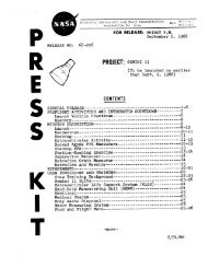
Nozzle ExtensionThe radiation cooled nozzle extension is attached to <strong>the</strong> combustionchamber case at <strong>the</strong> area ratio <strong>of</strong> 16:1 and extends to an exit arearatio <strong>of</strong> 47.5:1. Columbium alloy C-l03 was selected as <strong>the</strong> material for<strong>the</strong> nozzle extension because <strong>of</strong> its high temperature structural properties .An aluminide coating provides oxidation resistance and high emissivity .In addition to being able to survive <strong>the</strong> aerodynamic loads <strong>of</strong>firing and <strong>the</strong> vibration environment <strong>of</strong> launch and boost, a major designcriteria for <strong>the</strong> nozzle extension is that it be capable <strong>of</strong> collapsingwithout upsetting <strong>the</strong> Lunar Module should it strike a protrusion on <strong>the</strong>surface <strong>of</strong> <strong>the</strong> moon during landing.Figure 12.Aluminum Nozzle ExtensionCrushing Test SpecimenThe program <strong>of</strong>designing a nozzle extensionwhich would collapse 28 inchesat an impact velocity <strong>of</strong>10 ft/sec without absorbingan excessive amount <strong>of</strong> energystarted in 1963 with sometests <strong>of</strong> aluminum right circularcones . Figure 12 isrepresentative <strong>of</strong> one <strong>of</strong> <strong>the</strong>specimens . Variations <strong>of</strong>constant thickness, taper andcombinations <strong>of</strong> <strong>the</strong> two weretested. The test data ob tained provided assurance that<strong>the</strong> analytical methods werecorrect.Having confirmed <strong>the</strong>method <strong>of</strong> analysis, a nozzleextension was designed withHaynes 25 material as a choicesince <strong>the</strong> temperatures werepredicted to be well below <strong>the</strong>2400°F melting point <strong>of</strong> thatmaterial . Subsequent changesto <strong>the</strong> Lunar Module reduced<strong>the</strong> radiation cooling <strong>of</strong> <strong>the</strong>nozzle extension and <strong>the</strong>corresponding temperature pr<strong>of</strong>ileprediction exceeded2400°F. As a result Columbium alloy C-l03 was used on <strong>the</strong> new nozzle extensionsince that material, when coated with <strong>the</strong> aluminide coating, canwithstand temperatures up to 2700°F. The configuration consists <strong>of</strong> sheetwelded in segments, stepped down in thickness towards <strong>the</strong> exit plane. At<strong>the</strong> attachment plane to <strong>the</strong> combustion chamber, <strong>the</strong> thickness is 0 . 060 inchin order to have a stiff surface for <strong>the</strong> seal between components . Threeand one-half inches below that is a nine-inch segment 0.030 inch thick .The next l3-inch segment is 0.020 inch thick and <strong>the</strong> last 15 inches is0.010 inch thick. At <strong>the</strong> exit plane a titanium I-shaped ring is attached- 10 -
in order to provide stiffness during handling and launch and boost vibration.Figure 13 shows <strong>the</strong> temperatures measured during a high altitude test firing.2400f.----- 0.029V WALLDATA ARE MAXIMUM VALUES FROMTEST NO. HATS 060 • AEDC AD-lit -12TEMPERATURE.<strong>of</strong>200018001----- 0.017 ----iWALL1----0.010 --WALL1600~OL. ____" ____ ~ __ ~ ____ ~ ____" ____ ~ ____ ~~ m 24 m n H 40AREA RATIOFigure 13.Thicknesses shown in thischart are actual measurements<strong>of</strong> that specimen. One <strong>of</strong> <strong>the</strong>nozzle extensions which wasused on <strong>the</strong> qualification testengines is shown in Figure 14after <strong>the</strong> test was completed.Pro<strong>of</strong> that <strong>the</strong> nozzleextension would collapse asrequired without impartingforces large enough to upset<strong>the</strong> lunar vehicle during a10 ft per sec descent to <strong>the</strong>lunar surface was undertakenwith <strong>the</strong> aid <strong>of</strong> <strong>the</strong> testsetup shown in Figure 15.The columbium alloynozzle extension was attachedto a servo controlled hydrauliccylinder which provided energyFigure 14. <strong>LMDE</strong> Nozzle Extension necessary to collapse <strong>the</strong>nozzle extension exit flangeagainst <strong>the</strong> lower platform which was instrumented for measuring load. Surrounding<strong>the</strong> test specimen was a bank <strong>of</strong> quartz lamps which heated up <strong>the</strong>columbium to <strong>the</strong> temperature simulating <strong>the</strong> condition at lunar touchdown.The temperature gradient controlled during this test was 2l00°F at <strong>the</strong>- 11 -
Figure 15.Nozzle Extension in Crushing Test Fixture16:1 joint to l250°F at <strong>the</strong> exit plane . The 10 ft per sec impact velocitywas accomplished by compressing <strong>the</strong> nozzle extension 28 inches in less than1/2 second after several inches <strong>of</strong> free motion. Resultant loads andenergies recorded are shown in Figure 16 .10 15 20 25 30CRUS HIN G DISTANCE - INCHESFigure 16.- 12 -
Figure 17 shows <strong>the</strong> test specimen after <strong>the</strong> test. The tests performedearly in <strong>the</strong> program gave assurance that <strong>the</strong> analytical methods were correct ,<strong>the</strong>refore <strong>the</strong> risk taken by leaving <strong>the</strong> qualification crushing test tilllate in <strong>the</strong> program was small.Figure 17 .Columbium Nozzle ExtensionAfter Crushing TestThrottle Control LinkageWe have reviewed <strong>the</strong> structural design <strong>of</strong> <strong>the</strong> larger components<strong>of</strong> <strong>the</strong> <strong>LMDE</strong>. Now , we shall look at some <strong>of</strong> <strong>the</strong> small details which are <strong>of</strong>major importance in <strong>the</strong> function <strong>of</strong> this engine. The linkage between <strong>the</strong>throttle actuator, <strong>the</strong> flow control valves and <strong>the</strong> variable area injectordrive mechanism requires high precision. The ratio between <strong>the</strong> motion <strong>of</strong><strong>the</strong> flow control valves and <strong>the</strong> injector is 5:1. Total motion <strong>of</strong> <strong>the</strong>injector sleeve is 0.15 inch. A ten per cent increment in throttle settingis <strong>the</strong>refore a motion <strong>of</strong> only 0.003 inch. In order to maintain <strong>the</strong> positionrelationship between <strong>the</strong> injector sleeve and <strong>the</strong> flow control valves,looseness in <strong>the</strong> pivot bearings <strong>of</strong> <strong>the</strong> linkage had to be virtually eliminated.Ano<strong>the</strong>r constraint on <strong>the</strong> design was that <strong>the</strong> joints <strong>of</strong> <strong>the</strong>mechanism be capable <strong>of</strong> motion in a complete vacuum.Where possible, moving elements are connected by flexures. SeeFigure 3. Photographs <strong>of</strong> <strong>the</strong>se flexures are shown in Figure 18. Tensionand compression loads are transmitted through <strong>the</strong>se flexures while <strong>the</strong>ypermit relative rotation <strong>of</strong> <strong>the</strong> connected members. In order to insureagainst a structural failure <strong>of</strong> <strong>the</strong>se critical components, <strong>the</strong>y were designedwith redundant load paths . Ei<strong>the</strong>r side <strong>of</strong> <strong>the</strong> flexure is capable<strong>of</strong> full load and life should one side fail.- 13 -
(a)Cross BeamFlexure(b)Injector DriveFlexureFigure 18.ThrottleLinkageFlexuresIn those places where a flexural element was not practical, pivotbearings were used. The first concept was to use a non-metallic bearingfabricated <strong>of</strong> fiberglass and phenolic. Initial tests showed that <strong>the</strong> wearrate <strong>of</strong> <strong>the</strong> bearing and <strong>the</strong> compliance <strong>of</strong> <strong>the</strong> material exceeded <strong>the</strong> requirements.An all metal configuration was selected. The extremely simpledesign consists <strong>of</strong> a steel bushing with a steel pin - both coated withmolybdenum disulfide in an inorganic binder. This configuration also providesredundancy. The primary motion occurs between <strong>the</strong> pin and <strong>the</strong> innerdiameter <strong>of</strong> <strong>the</strong> bushing. Should this not function, <strong>the</strong> bushing wouldrotate in <strong>the</strong> bore <strong>of</strong> <strong>the</strong> link <strong>of</strong> <strong>the</strong> mechanism. To substantiate <strong>the</strong>reliability <strong>of</strong> <strong>the</strong> design, an assembly <strong>of</strong> <strong>the</strong> throttle linkage was subjectedto a cycling test in a vacuum chamber at 8 x 10- 10 Torr. Criteriafor success was completion <strong>of</strong> 10,000 cycles (33 mission duty cycles) withno significant change in load.Pro<strong>of</strong> that <strong>the</strong> complete assembly met <strong>the</strong> requirements for ruggedness,rigidity and repeatability was obtained in <strong>the</strong> deflection test shownin Figure 19. In this test motions <strong>of</strong> <strong>the</strong> two flow control valve pintles,- 14 -
Figure 19.Deflection Test <strong>of</strong>Throttle Linkagethrottle actuator and <strong>the</strong> injectorsleeve were observed and recordedunder <strong>the</strong> influence <strong>of</strong> variousfluid pressures and chamberpressures.Bellows AssembliesBoth <strong>the</strong> flow controlvalves and <strong>the</strong> injector driveassembly contain a moving elementused to control propellant flowrates while containing <strong>the</strong> propellantunder pressure . Bellows areused as dynamic seals, permittingdirect external actuation <strong>of</strong> internalmetering surfaces . The configurationselected to accomplishthis was a thin wall (0.006 to0.010 inch) stainless steel weldedbellows. Figure 20 shows <strong>the</strong>location <strong>of</strong> <strong>the</strong> bellows in <strong>the</strong>flow control valve. A similarapplication <strong>of</strong> bellows is used in<strong>the</strong> injector drive . In 1963 atest program to verify <strong>the</strong> str engthand life <strong>of</strong> <strong>the</strong>se bellows was instituted.Ten thousand cycles (33mission duty cycles) was selectedas a minimum life requirement . The original configuration did not survive<strong>the</strong> tests. Fatigue cracks occurred in <strong>the</strong> single ply convolution at <strong>the</strong>weld joints. The final configuration (Figure 21) a two-ply design with0 . 004 inch convolutions successfully passed all <strong>of</strong> <strong>the</strong> tests which consistedPINTLEBEARINGINLETDIFFUSERFLOW SPLITTERVENTURI THROATFigure 20.<strong>LMDE</strong> Flow Control Valve- 15 -
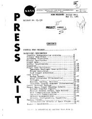
Figure 21.Figure 22.Section <strong>of</strong> Two-PlyBellowsComponent Test <strong>of</strong>Inlet Lines , FlowControl Valve andShut<strong>of</strong>f Valve<strong>of</strong> cycles <strong>of</strong> surge pressure, andextension and compression cyclesunder static pressure, followedby burst tests in excess <strong>of</strong> tentimes <strong>the</strong> design pressure.Here again, early testing<strong>of</strong> a component revealed a designdeficiency which was correctedwithout affecting <strong>the</strong> engine developmentschedule. The final configuration(two-ply bellows) hadan additional advantage <strong>of</strong> havinga lower spring rate than <strong>the</strong> singleply bellows originally proposed.Testing <strong>of</strong> <strong>the</strong> bellowscontinued when <strong>the</strong>y were combinedinto assemblies. A componentdesign verification test <strong>of</strong> <strong>the</strong>flow control valve included longterm exposure to propellants, shockand vibration tests representinglaunch aud boost and engine firing,and 33 mission duty cycles <strong>of</strong> pressurizationand actuation. Uponcompletion <strong>of</strong> <strong>the</strong>se exposures, <strong>the</strong>components were required to pass<strong>the</strong>ir acceptance criteria.Figure 22 shows <strong>the</strong> arrangementfor testing <strong>the</strong> flow control valve,shut<strong>of</strong>f valve and inlet line asa subassembly.Engine TestsAs <strong>the</strong> next step in <strong>the</strong>test program, an assembly <strong>of</strong> <strong>the</strong>head end - composed <strong>of</strong> injectormanifold, injector drive, ducting,shut<strong>of</strong>f valves, flow control valves,throttle actuator, and throttlelinkage - was subjected to <strong>the</strong> completequalification level <strong>of</strong> vibrationenvironment (Figure 23). Inorder to establish <strong>the</strong> margin <strong>of</strong>strength built into <strong>the</strong> head endassembly, upon completion <strong>of</strong> acceptancetests following <strong>the</strong> qualificationtests, it was tested to 125% <strong>of</strong><strong>the</strong> qual levels, <strong>the</strong>n again to 150%in an attempt to find out whenfailure would occur. Finallyfailure did occur at 175% <strong>of</strong>- 16 -
Figure 23.Figure 24.Vibration Test <strong>of</strong>Head End Assembly<strong>LMDE</strong> Installed in HighAltitude Test Standqualification vibration tests <strong>of</strong><strong>the</strong> complete engine.At this point, only <strong>the</strong>combustion chamber and nozzle extensionhad not been subjected to <strong>the</strong>launch and boost vibration environment.They had however receivedmany thousands <strong>of</strong> seconds <strong>of</strong>reactive firing during <strong>the</strong> developmenttests <strong>of</strong> <strong>the</strong> engine in <strong>the</strong>TRW Sea Level Vertical Engine TestStands (VETS) and High AltitudeTest Stand (HATS). As a lastmeasure before <strong>the</strong> start <strong>of</strong> <strong>the</strong>qualification series <strong>of</strong> tests, adevelopment engine was vibrationtested to <strong>the</strong> qualification environmentand <strong>the</strong>n successfullyfired in HATS for a full missionduty cycle. The engine shown inFigure 24 installed in <strong>the</strong> HATSfacility is awaiting final checkoutprior to mission duty cyclefiring. The support structureto which <strong>the</strong> engine is attachedmeasures thrust and six components<strong>of</strong> thrust to determinethrust alignment.Analysis and Test for Dynamic LoadsA linear spring-massanalogy for <strong>the</strong> LM Descent Enginewas developed as a design tool tocompute <strong>the</strong> dynamic loads on <strong>the</strong>engine structure . Initially,this analysis consisted <strong>of</strong> asingle mass, five degree-<strong>of</strong>freedomsystem. Two componentmasses were added to <strong>the</strong> initialanalysis, increasing <strong>the</strong> number <strong>of</strong>degrees <strong>of</strong> freedom to eleven.Hand computation <strong>of</strong> <strong>the</strong> dynamicloads became very time consumingso <strong>the</strong> response equations were programedfor <strong>the</strong> digital computer.The first vibration test<strong>of</strong> <strong>the</strong> gimbal, described earlier,indicated that a strong enginetorsional mode existed (enginerotation about <strong>the</strong> thrust axis).The corresponding rotationalcoordinate,e, had been leftx- 17 -
out <strong>of</strong> <strong>the</strong> first two analyses on <strong>the</strong> assumption that <strong>the</strong> torsional mode wouldnot be strongly excited. Based on this experience, a third and final springmassmodel was developed. The primary purpose <strong>of</strong> this analysis was to include<strong>the</strong> torsional coordinate. In addition, <strong>the</strong> gimbal was represented astwo support masses with a system <strong>of</strong> springs connecting <strong>the</strong>m to <strong>the</strong> main enginemass. Each side <strong>of</strong> <strong>the</strong> gimbal is connected to <strong>the</strong> Lunar Module with a fourmembertruss . Modeling <strong>the</strong> gimbal in <strong>the</strong> above manner facilitated representation<strong>of</strong> <strong>the</strong> support trusses as a system <strong>of</strong> springs .The final model is basically a three mass, twelve degree-<strong>of</strong>-freedomsystem (Figure 25) . The motion <strong>of</strong> <strong>the</strong> main engine mass is described by sixcoordinates, three displacements and three rotations, in a rectangularcoordinate system with <strong>the</strong> origin at <strong>the</strong> center <strong>of</strong> <strong>the</strong> gimbal. The twogimbal/support mass motions are described by three displacement coordinateseach.'3FINAL SPRING - MASS MODEL OF ENGINETHRUST ENDSUPPORT MASS, '"3"SUPPORT MASS , m 2HEAO ENDKG,,' K ' K - GIMBAL SPRINGSCy GzK, - GIMBAL TORSIONAL SPRINGK,,2' K y2' 1
Table 1 presents <strong>the</strong> qualification sinusoidal and random vibrationtest levels applied to <strong>the</strong> attachment interface on <strong>the</strong> gimbal frame.The configuration <strong>of</strong> <strong>the</strong> final engine vibration test specimen is shown inFigure 26. It was necessary to mount <strong>the</strong> engine upside- down in order tokeep <strong>the</strong> mass <strong>of</strong> <strong>the</strong> supporting fixture low, since <strong>the</strong> mass <strong>of</strong> <strong>the</strong> fixtureplus <strong>the</strong> engine approached <strong>the</strong> maximum limits <strong>of</strong> <strong>the</strong> shaker . The supportingstructure is <strong>the</strong> same as used for <strong>the</strong> gimbal test shown in Figures 6and 7.TABLE 1VIBRATION LEVELS FOR QUALIFICATIONTEST (LAUNCH AND BOOST)SINUSOIDAL VIBRATIONFlightEnvironmentFrequencyInput LevelSweep RateLaunch andBoost5-1616-1000.2 inches d.a.2.5 g vector3 oct/min upand downRANDOM VIBRATIONPhaseFrequency Band(cps)Power SpectralDensityTime perTest AxisLaunch 10-23 12 db/octave rise23-80 0.025 g2/cpsand 80-100 12 db/~ctave rise100-1000 0 . 06 g /cpsBoost 1000-12000 12 db/octave fall1200-2000 0.025 g2/cps5 minutes<strong>of</strong> randomvibrationTable 2 presents a comparison <strong>of</strong> <strong>the</strong> calculated and measured frequenciesand loads. It is seen that <strong>the</strong> final ma<strong>the</strong>matical model permitsaccurate estimation <strong>of</strong> <strong>the</strong> dynamic characteristics <strong>of</strong> <strong>the</strong> engine.The analytical model has been used primarily to determine <strong>the</strong>effects <strong>of</strong> design changes . For example, following vibration <strong>of</strong> <strong>the</strong> gimbalwith a mass simulated engine during design verification testing, <strong>the</strong> stiffnesses<strong>of</strong> <strong>the</strong> support trusses that mount <strong>the</strong> engine in <strong>the</strong> Lunar Modulewere decreased to save weight. The ma<strong>the</strong>matical model was used to determine<strong>the</strong> effects <strong>of</strong> <strong>the</strong> s<strong>of</strong>ter mounting system on engine dynamic response. O<strong>the</strong>rsimilar analyses include <strong>the</strong> effects <strong>of</strong> changing <strong>the</strong> gimbal actuator stiffness,effects <strong>of</strong> changing <strong>the</strong> engine c . g . location, and an evaluation <strong>of</strong> <strong>the</strong>vibration test fixture.In addition, <strong>the</strong> dynamic loads on <strong>the</strong> gimbal nozzle extension andthrottle control system have been computed for use in associated stressanalyses <strong>of</strong> <strong>the</strong>se components. The loads computed for <strong>the</strong> throttle control- 19 -
Figure 26.Vibration Test <strong>of</strong> <strong>LMDE</strong>system, verified by <strong>the</strong> results <strong>of</strong> <strong>the</strong> engine mass simulator vibration testresults, allowed simplification <strong>of</strong> <strong>the</strong> structure mounting <strong>the</strong> throttlecontrol system on <strong>the</strong> engine.TABLE 2COMPARISON OF ANALYTICAL WITH TESTDYNAMIC RESPONSE OF ENGINEANALYSISMODALFREQUENCIES(cps)(All Axes)11.212.627.533.137.9QUAL LEVELTEST RESONANTFREQUENCIES(cps)AxisX Y ZMAXIMUM GIMBAL LOADSLOAD TEST ANALYSIS11.4 11.6Mx12.7 12.728170 in-lbs 31330 in-lbs28.4 29.2 1:'y 5580 lbs 5220 lbs30.8 34.1 34.3 Px 7105 lbs 7520 lbs39.0 38.7 Pz 6723 lbs 6275 lbs- 20 -
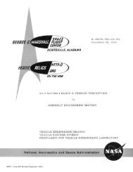
SummaryThus at <strong>the</strong> start <strong>of</strong> <strong>the</strong> engine qualification test series, everycomponent <strong>of</strong> <strong>the</strong> TRW Lunar Module Descent Engine had been subjected to tests -step by step - first as a unit, <strong>the</strong>n in its next assembly, <strong>the</strong>n as a majorsubassembly, and again as a complete engine. Simultaneous with all <strong>of</strong> <strong>the</strong>mechanical and structural testing described, reactive testing was being performedin <strong>the</strong> TRW facilities at San Juan Capistrano and at <strong>the</strong> USAF ArnoldEngineering Development Center at Tullahoma, Tennessee, and at NASA's 1Mvehicle test facility at White Sands, New Mexico. Table 3 presents <strong>the</strong>detail <strong>of</strong> this test experience to 1 July 1967.TABLE 3<strong>LMDE</strong> REACTIVE TEST SUMMARYNo. <strong>of</strong>NewBuildsNo. <strong>of</strong>StartsFiringDuration(seconds)Injector Tests1,80070,374Throttling Head EndAssemblies on WaterCooled CombustionChambers2894161,666Ablative EnginesSea Level (E = 2:1)21675,368High Altitude (E = 47 . 5:1)3524226,549Total Test Experience3,050163,957The successful completion <strong>of</strong> qualification <strong>of</strong> <strong>the</strong> TRW <strong>LMDE</strong> demonstratesthat, in order to develop light weight and reliable high performancerocket engines in a short time span, it is necessary to substantiate all <strong>of</strong><strong>the</strong> component design concepts early in <strong>the</strong> program. A carefully designedcomponent development test program verifies <strong>the</strong> assumptions made duringdesign analysis and provides assurance that tests <strong>of</strong> <strong>the</strong> complete systemwill proceed without unexpected difficulty. The engine shown in Figure 28being prepared for shipment to Grumman Aircraft Engineering Corporation,- 21 -
designers and builders <strong>of</strong> <strong>the</strong> Lunar Module, is one <strong>of</strong> several being testedas part <strong>of</strong> <strong>the</strong> complete propulsion system and space vehicle in order toassure success for <strong>the</strong> first Lunar Module flight later this year.Figure 27.<strong>LMDE</strong> Being Prepared for Shipment to <strong>the</strong>Grumman Aircraft Engineering Corporation- 22 -