Mechanical Design of the LMDE.pdf - Heroicrelics
Mechanical Design of the LMDE.pdf - Heroicrelics
Mechanical Design of the LMDE.pdf - Heroicrelics
- No tags were found...

You also want an ePaper? Increase the reach of your titles
YUMPU automatically turns print PDFs into web optimized ePapers that Google loves.
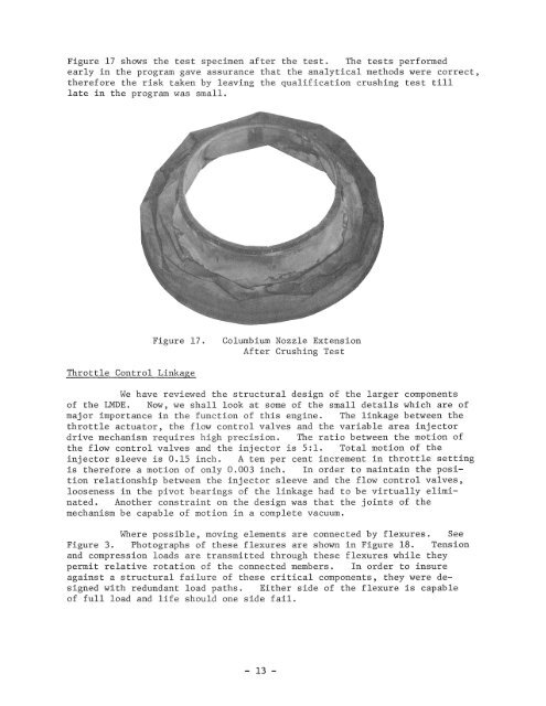
Figure 17 shows <strong>the</strong> test specimen after <strong>the</strong> test. The tests performedearly in <strong>the</strong> program gave assurance that <strong>the</strong> analytical methods were correct ,<strong>the</strong>refore <strong>the</strong> risk taken by leaving <strong>the</strong> qualification crushing test tilllate in <strong>the</strong> program was small.Figure 17 .Columbium Nozzle ExtensionAfter Crushing TestThrottle Control LinkageWe have reviewed <strong>the</strong> structural design <strong>of</strong> <strong>the</strong> larger components<strong>of</strong> <strong>the</strong> <strong>LMDE</strong>. Now , we shall look at some <strong>of</strong> <strong>the</strong> small details which are <strong>of</strong>major importance in <strong>the</strong> function <strong>of</strong> this engine. The linkage between <strong>the</strong>throttle actuator, <strong>the</strong> flow control valves and <strong>the</strong> variable area injectordrive mechanism requires high precision. The ratio between <strong>the</strong> motion <strong>of</strong><strong>the</strong> flow control valves and <strong>the</strong> injector is 5:1. Total motion <strong>of</strong> <strong>the</strong>injector sleeve is 0.15 inch. A ten per cent increment in throttle settingis <strong>the</strong>refore a motion <strong>of</strong> only 0.003 inch. In order to maintain <strong>the</strong> positionrelationship between <strong>the</strong> injector sleeve and <strong>the</strong> flow control valves,looseness in <strong>the</strong> pivot bearings <strong>of</strong> <strong>the</strong> linkage had to be virtually eliminated.Ano<strong>the</strong>r constraint on <strong>the</strong> design was that <strong>the</strong> joints <strong>of</strong> <strong>the</strong>mechanism be capable <strong>of</strong> motion in a complete vacuum.Where possible, moving elements are connected by flexures. SeeFigure 3. Photographs <strong>of</strong> <strong>the</strong>se flexures are shown in Figure 18. Tensionand compression loads are transmitted through <strong>the</strong>se flexures while <strong>the</strong>ypermit relative rotation <strong>of</strong> <strong>the</strong> connected members. In order to insureagainst a structural failure <strong>of</strong> <strong>the</strong>se critical components, <strong>the</strong>y were designedwith redundant load paths . Ei<strong>the</strong>r side <strong>of</strong> <strong>the</strong> flexure is capable<strong>of</strong> full load and life should one side fail.- 13 -