Mechanical Design of the LMDE.pdf - Heroicrelics
Mechanical Design of the LMDE.pdf - Heroicrelics
Mechanical Design of the LMDE.pdf - Heroicrelics
- No tags were found...

You also want an ePaper? Increase the reach of your titles
YUMPU automatically turns print PDFs into web optimized ePapers that Google loves.
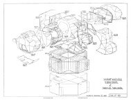
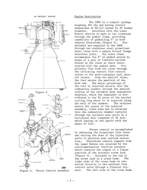
Engine DescriptionCOMffNSAT1NGSPItiNGFigure 2.The <strong>LMDE</strong> is a compact packageweighing 394 lbs and having overalldimensions <strong>of</strong> 90-1/2 inches by 59 inchesdiameter. Interface with <strong>the</strong> LunarModule vehicle is made at two trunnionsthrough <strong>the</strong> gimbal frame, providingcapability <strong>of</strong> gimballing 6° in bothlateral directions (Figure 2). Propellantsare supplied to <strong>the</strong> <strong>LMDE</strong>through two stainless steel propellantinlet lines with a simple bolted flangeinterface joint. The inlet linesaccommodate <strong>the</strong> 6° <strong>of</strong> gimbal motion bymeans <strong>of</strong> a pair <strong>of</strong> flexible bellowswelded in <strong>the</strong> lines at <strong>the</strong>ir intersectionwith <strong>the</strong> gimbal axes. Propellantsflow from <strong>the</strong> lines through<strong>the</strong> cavitating venturi flow controlvalves to <strong>the</strong> quad-redundant ball shut<strong>of</strong>fvalves. From <strong>the</strong> shut<strong>of</strong>f valve,<strong>the</strong> fuel enters <strong>the</strong> manifold <strong>of</strong> <strong>the</strong>head end. The major percentage <strong>of</strong><strong>the</strong> fuel is injected axially into <strong>the</strong>combustion chamber through <strong>the</strong> annularorifice <strong>of</strong> <strong>the</strong> variable area concentricinjector, while <strong>the</strong> remainder is distributedto <strong>the</strong> 36 ports <strong>of</strong> <strong>the</strong> barriercooling ring where it is injected along<strong>the</strong> wall <strong>of</strong> <strong>the</strong> chamber. The oxidizerenters <strong>the</strong> center <strong>of</strong> <strong>the</strong> injectorassembly, flows down and is directedinto <strong>the</strong> combustion chamber radiallythrough <strong>the</strong> variable area ports in ahorizontal disc composed <strong>of</strong> 36 jetswhich impinge on and ignite with <strong>the</strong>sheet <strong>of</strong> fuel.Figure 3.I flOW"'''LYE.!l!!!Thrust Control AssemblyThrust control is accomplishedby adjusting <strong>the</strong> propellant flow ratesand varying <strong>the</strong> area <strong>of</strong> <strong>the</strong> injectionports to maintain near uniform velocities.Electrical control signals from<strong>the</strong> Lunar Module are received by <strong>the</strong>electromechanical throttle actuatorwhich converts <strong>the</strong> signal to a linearposition <strong>of</strong> <strong>the</strong> actuator screw jack(Figure 3). Attached to <strong>the</strong> top <strong>of</strong><strong>the</strong> screw jack is a cross beam. Theright side <strong>of</strong> <strong>the</strong> cross beam is connecteddirectly to <strong>the</strong> oxidizer flowcontrol valve through a flexural element.The left side <strong>of</strong> <strong>the</strong> cross beam- 2 -