Mechanical Design of the LMDE.pdf - Heroicrelics
Mechanical Design of the LMDE.pdf - Heroicrelics
Mechanical Design of the LMDE.pdf - Heroicrelics
- No tags were found...

Create successful ePaper yourself
Turn your PDF publications into a flip-book with our unique Google optimized e-Paper software.
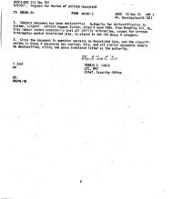
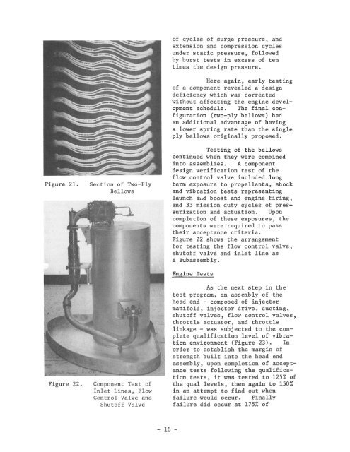
Figure 21.Figure 22.Section <strong>of</strong> Two-PlyBellowsComponent Test <strong>of</strong>Inlet Lines , FlowControl Valve andShut<strong>of</strong>f Valve<strong>of</strong> cycles <strong>of</strong> surge pressure, andextension and compression cyclesunder static pressure, followedby burst tests in excess <strong>of</strong> tentimes <strong>the</strong> design pressure.Here again, early testing<strong>of</strong> a component revealed a designdeficiency which was correctedwithout affecting <strong>the</strong> engine developmentschedule. The final configuration(two-ply bellows) hadan additional advantage <strong>of</strong> havinga lower spring rate than <strong>the</strong> singleply bellows originally proposed.Testing <strong>of</strong> <strong>the</strong> bellowscontinued when <strong>the</strong>y were combinedinto assemblies. A componentdesign verification test <strong>of</strong> <strong>the</strong>flow control valve included longterm exposure to propellants, shockand vibration tests representinglaunch aud boost and engine firing,and 33 mission duty cycles <strong>of</strong> pressurizationand actuation. Uponcompletion <strong>of</strong> <strong>the</strong>se exposures, <strong>the</strong>components were required to pass<strong>the</strong>ir acceptance criteria.Figure 22 shows <strong>the</strong> arrangementfor testing <strong>the</strong> flow control valve,shut<strong>of</strong>f valve and inlet line asa subassembly.Engine TestsAs <strong>the</strong> next step in <strong>the</strong>test program, an assembly <strong>of</strong> <strong>the</strong>head end - composed <strong>of</strong> injectormanifold, injector drive, ducting,shut<strong>of</strong>f valves, flow control valves,throttle actuator, and throttlelinkage - was subjected to <strong>the</strong> completequalification level <strong>of</strong> vibrationenvironment (Figure 23). Inorder to establish <strong>the</strong> margin <strong>of</strong>strength built into <strong>the</strong> head endassembly, upon completion <strong>of</strong> acceptancetests following <strong>the</strong> qualificationtests, it was tested to 125% <strong>of</strong><strong>the</strong> qual levels, <strong>the</strong>n again to 150%in an attempt to find out whenfailure would occur. Finallyfailure did occur at 175% <strong>of</strong>- 16 -