Mechanical Design of the LMDE.pdf - Heroicrelics
Mechanical Design of the LMDE.pdf - Heroicrelics
Mechanical Design of the LMDE.pdf - Heroicrelics
- No tags were found...

You also want an ePaper? Increase the reach of your titles
YUMPU automatically turns print PDFs into web optimized ePapers that Google loves.
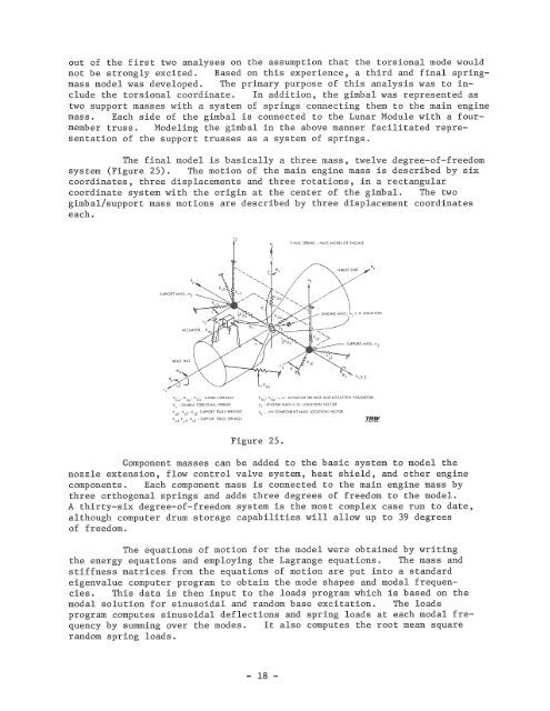
out <strong>of</strong> <strong>the</strong> first two analyses on <strong>the</strong> assumption that <strong>the</strong> torsional mode wouldnot be strongly excited. Based on this experience, a third and final springmassmodel was developed. The primary purpose <strong>of</strong> this analysis was to include<strong>the</strong> torsional coordinate. In addition, <strong>the</strong> gimbal was represented astwo support masses with a system <strong>of</strong> springs connecting <strong>the</strong>m to <strong>the</strong> main enginemass. Each side <strong>of</strong> <strong>the</strong> gimbal is connected to <strong>the</strong> Lunar Module with a fourmembertruss . Modeling <strong>the</strong> gimbal in <strong>the</strong> above manner facilitated representation<strong>of</strong> <strong>the</strong> support trusses as a system <strong>of</strong> springs .The final model is basically a three mass, twelve degree-<strong>of</strong>-freedomsystem (Figure 25) . The motion <strong>of</strong> <strong>the</strong> main engine mass is described by sixcoordinates, three displacements and three rotations, in a rectangularcoordinate system with <strong>the</strong> origin at <strong>the</strong> center <strong>of</strong> <strong>the</strong> gimbal. The twogimbal/support mass motions are described by three displacement coordinateseach.'3FINAL SPRING - MASS MODEL OF ENGINETHRUST ENDSUPPORT MASS, '"3"SUPPORT MASS , m 2HEAO ENDKG,,' K ' K - GIMBAL SPRINGSCy GzK, - GIMBAL TORSIONAL SPRINGK,,2' K y2' 1