Mechanical Design of the LMDE.pdf - Heroicrelics
Mechanical Design of the LMDE.pdf - Heroicrelics
Mechanical Design of the LMDE.pdf - Heroicrelics
- No tags were found...

You also want an ePaper? Increase the reach of your titles
YUMPU automatically turns print PDFs into web optimized ePapers that Google loves.
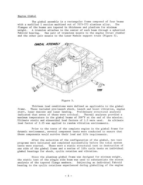
Engine GimbalThe gimbal assembly is a rectangular frame composed <strong>of</strong> four beamswith a modified I section machined out <strong>of</strong> 7075-T73 aluminum alloy. Theflanges <strong>of</strong> <strong>the</strong> beams are tapered in thickness and planform for minimumweight. A trunnion attaches to <strong>the</strong> center <strong>of</strong> each beam through a sphericalFabroid bearing. One pair <strong>of</strong> trunnions mounts to <strong>the</strong> engine thrust chamberand <strong>the</strong> o<strong>the</strong>r pair mounts to <strong>the</strong> Lunar Module support truss (Figure 5) .Figure 5.Thirteen load conditions were defined as applicable to <strong>the</strong> gimbalframe. These included pre-launch shock, launch and boost vibration, enginestart, lunar descent and lunar landing. Preliminary structural analysisindicated that seven <strong>of</strong> <strong>the</strong>se were critical. Thermal analyses provided amaximum temperature in <strong>the</strong> gimbal beams <strong>of</strong> 200°F at <strong>the</strong> end <strong>of</strong> <strong>the</strong> mission .Ultimate static and sinusoidal load factors <strong>of</strong> 1.5 were used. An ultimateload factor <strong>of</strong> 2.25 was applied to random vibration environments.Prior to <strong>the</strong> tests <strong>of</strong> <strong>the</strong> complete engine in <strong>the</strong> gimbal frame fordynamic environment, several component tests were conducted to ensure that<strong>the</strong>se components would survive <strong>the</strong>ir load and life requirements.After <strong>the</strong> selection <strong>of</strong> <strong>the</strong> configuration <strong>of</strong> <strong>the</strong> gimbal, two testprograms were initiated and completed successfully before <strong>the</strong> total systemtests were started. These were a static structural test to destruction <strong>of</strong>one side <strong>of</strong> <strong>the</strong> gimbal frame and a series <strong>of</strong> life cycle tests on individualgimbal bearings for shock, cyclic rotation and vibration.Since <strong>the</strong> aluminum gimbal frame was designed for m1n1mum weight ,<strong>the</strong> static test <strong>of</strong> <strong>the</strong> single side beam was used to substantiate <strong>the</strong> stressanalysis <strong>of</strong> <strong>the</strong> tapered flange members. Subjecting an individual Fabroidbearing to <strong>the</strong> cyclic rotations experienced during gimballing <strong>of</strong> <strong>the</strong> engine- 4 -