Mechanical Design of the LMDE.pdf - Heroicrelics
Mechanical Design of the LMDE.pdf - Heroicrelics
Mechanical Design of the LMDE.pdf - Heroicrelics
- No tags were found...

You also want an ePaper? Increase the reach of your titles
YUMPU automatically turns print PDFs into web optimized ePapers that Google loves.
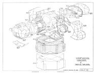
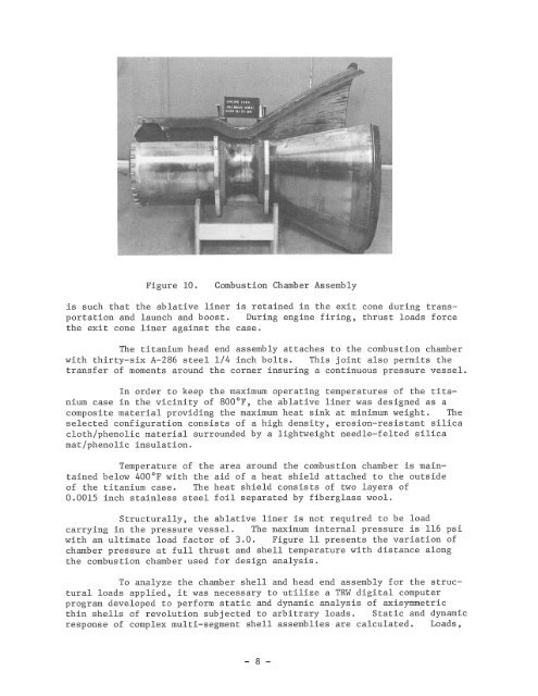
Figure 10.Combustion Chamber Assemblyis such that <strong>the</strong> ablative liner is retained in <strong>the</strong> exit cone during transportationand launch and boost. During engine firing, thrust loads force<strong>the</strong> exit cone liner against <strong>the</strong> case.The titanium head end assembly attaches to <strong>the</strong> combustion chamberwith thirty-six A-286 steel 1/4 inch bolts. This joint also permits <strong>the</strong>transfer <strong>of</strong> moments around <strong>the</strong> corner insuring a continuous pressure vessel.In order to keep <strong>the</strong> maximum operating temperatures <strong>of</strong> <strong>the</strong> titaniumcase in <strong>the</strong> vicinity <strong>of</strong> 800°F, <strong>the</strong> ablative liner was designed as acomposite material providing <strong>the</strong> maximum heat sink at minimum weight. Theselected configuration consists <strong>of</strong> a high density, erosion-resistant silicacloth/phenolic material surrounded by a lightweight needle-felted silicamat/phenolic insulation.Temperature <strong>of</strong> <strong>the</strong> area around <strong>the</strong> combustion chamber is maintainedbelow 400°F with <strong>the</strong> aid <strong>of</strong> a heat shield attached to <strong>the</strong> outside<strong>of</strong> <strong>the</strong> titanium case. The heat shield consists <strong>of</strong> two layers <strong>of</strong>0.0015 inch stainless steel foil separated by fiberglass wool.Structurally, <strong>the</strong> ablative liner is not required to be loadcarrying in <strong>the</strong> pressure vessel. The maximum internal pressure is 116 psiwith an ultimate load factor <strong>of</strong> 3.0. Figure 11 presents <strong>the</strong> variation <strong>of</strong>chamber pressure at full thrust and shell temperature with distance along<strong>the</strong> combustion chamber used for design analysis.To analyze <strong>the</strong> chamber shell and head end assembly for <strong>the</strong> structuralloads applied, it was necessary to utilize a TRW digital computerprogram developed to perform static and dynamic analysis <strong>of</strong> axisymmetricthin shells <strong>of</strong> revolution subjected to arbitrary loads. Static and dynamicresponse <strong>of</strong> complex multi-segment shell assemblies are calculated. Loads,- 8 -