
Create successful ePaper yourself
Turn your PDF publications into a flip-book with our unique Google optimized e-Paper software.
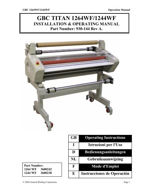
<strong>GBC</strong> <strong>1264WF</strong>/<strong>1244WF</strong>Operation ManualPRE-INSTALLATIONBefore a <strong>1264WF</strong>/<strong>1244WF</strong> Laminator can be installed,ensure the following requirements are met:1. Are doorways and hallways wide enough for thelaminator to be moved to the installation site?2. Is there ample room for the laminator? A work area must be established that allows foroperation in both the front and rear of thelaminator and provides space for efficientmaterial flow.3. Is the environment appropriate for the laminator? The laminator requires a clean, dust and vaporfree environment to operate properly. Avoid locating the laminator near sources of heator cold. Avoid locating the laminator in thedirect path of forced, heated or cooled air.CAUTION: Air flow can cause unevenheating / cooling of the rollers and result inpoor output quality.4. Have you contacted a certified electrician to wirethe receptacle and ensure that adequate power isbeing supplied, having the appropriate capacity,over current protection and safety lockoutsavailable?<strong>GBC</strong> 1264 WF/1244 WF Requires: 230V at 60Hz with 30 amps single phase. <strong>1264WF</strong>: Nema 6-30P 30A 230V Receptacle. <strong>1244WF</strong>: Nema 6-20P 20A 230V Receptacle.The machines are supplied with Male Plugs.INSTALLATION1. Shipping damage should be brought to the immediate attention of the delivering carrier.2. With assistance, carefully roll the laminator into position over flat and even surfaces.3. The laminator should be positioned to allow exiting film to flow freely to the floor or a work table. Accumulation oflaminate immediately behind the laminator as it exits the equipment may cause the film to wrap around the pull rollers,resulting in a “jammed” condition.4. Avoid locating the laminator near sources of heat or cold. Avoid locating the laminator in the direct path of forced,heated or cooled air.5. Once the laminator has been properly positioned, lock the castors in place. Locking the castors prevent the machinefrom rolling during set up, operation or servicing.6. Connect the attachment plug provided with the laminator to a suitably grounded outlet. Avoid connecting otherequipment to the same branch circuit to which the laminator is connected, as this may result in nuisance tripping ofcircuit breakers or blowing fuses.Note:Machine must be leveled to ensure best performance. Level the machine by lowering both the main and pull rolls.Lay a level on top of the main and pull rolls. Then, check level from main roll to pull roll on right and left side of theroll. Finally, check by placing the level diagonally across lower main to lower pull rolls.© 2006 General Binding Corporation Page 6
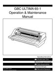
<strong>GBC</strong> <strong>1264WF</strong>/<strong>1244WF</strong>Operation ManualSection 1: Detailed SpecificationsSpecifications provide all of the technical data forthe Titan <strong>1244WF</strong> &<strong>1264WF</strong>Description:A high speed laminator for the graphic artsprofessional as well as for the manufacturerwho produces promotional pieces in-house. Anew elegant design, low power consumptionand first class safety and quality assurances.Features:Roller heating technologyIndependent control of each heaterThermal and cold lamination capabilitiesUnique vented cooling systemMounting capabilities to5/8 th in.-15mm.Easy to use control panel9 Programmable job settingsLCD temperature displays for each heat rollerRear out put slitter.Swing out shafts for ease of loading film.In-Line slitters.Accushield capable.Applications:Encapsulation-Promotional-materials, posters,counter cards, POP displays, calendars,instructional displays, phone & debit cards,blueprints, menus, maps, flipcharts, etc.© 2006 General Binding Corporation Page 7
<strong>GBC</strong> <strong>1264WF</strong>/<strong>1244WF</strong>Operation ManualHeater Wattage:1264 WF:<strong>1264WF</strong> CE:4500W / Heater3300W / Heater1244 WF:<strong>1244WF</strong> CE:3000 W / HeaterAmperage draw:1264 WF:Drive Motor=3.3 Amps.Fan Motor=0.5 Amps.Motors and Heater=25 Amps.<strong>1264WF</strong> CE:Drive Motor=3.3 Amps.Fan Motor=0.5 Amps.Motors and Heater=13 Amps.1244 WF:<strong>1244WF</strong> CE:Drive Motor=3.3 AmpsFan Motor=0.5 AmpsMotors and Heater=12AmpsD/C Voltage used:36 VDC Motor Voltage24 VDC Fan MotorA/C Voltage Used:230 VAC Recommended…(Not to exceed240VAC)© 2006 General Binding Corporation Page 10
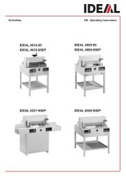
<strong>GBC</strong> <strong>1264WF</strong>/<strong>1244WF</strong>Operation ManualConnectors for 1264 WFConnectors for 1244 WFNEMA 6-20 PNEMA 6-30 PNEMA 6-30 RNEMA 6-20 R© 2006 General Binding Corporation Page 11
<strong>GBC</strong> <strong>1264WF</strong>/<strong>1244WF</strong>Operation ManualSection 5: DimensionsWeight:1264 WF:<strong>1264WF</strong> CE:Crated: 750 lbs. (340 kg.)Uncrated: 600 lbs. (272 kg.)1244 WF:<strong>1244WF</strong> CE:Crated: 350 lbs (159 kg.)Uncrated: 275 lbs (125 kg.)Dimensions:1264 WF:<strong>1264WF</strong> CE:1244 WF:<strong>1244WF</strong> CE:Crated: 58 in.(H) x 87 in. (W) x 40 in. (D)147 cm. (H) x 221 cm. (W) x 102 cm. (D)Uncrated: 49in(H) x 77.25 in.(W) x 25.5 in. (D)124 cm. (H) x196 cm. (W) x65cm. (D)Crated: 57 in.(H) x 68 in. (W) x 38 in. (D)145 cm. (H) x 173 cm. (W) x 97 cm. (D)Uncrated: 49in(H) x 77.25 in.(W) x 25.5 in. (D)124 cm. (H) x145 cm. (W) x65cm. (D)Nip Height:35.63 in (91cm.)© 2006 General Binding Corporation Page 12
<strong>GBC</strong> <strong>1264WF</strong>/<strong>1244WF</strong>Operation ManualSection 6: Know your LaminatorThis section is intended to aide the user in becoming more familiar with the 1244 WF & <strong>1264WF</strong> laminators. Refer back to this section if you have questions regarding references to certainparts of the laminator in this laminator.1.) Safety Shield 9.) Rewind Clutch Adjustment Knob2.) Control Panel 10.) Rewind Shaft & Rewind Tube3.) Feed Table 11.) Rear Slitter4.) Lower Film Shaft/Unwind Shaft 12.) Power Switch5.) Upper Film Shaft/Unwind Shaft 13.) Foot Pedal6.) Unwind Brake 14.) Power Cord7.) Pressure Plate 15.) Web Clutch8.) Emergency Stop/E-Stop 16.) Roller Lift Handle/Gap Adjustment Handle© 2006 General Binding Corporation Page 13
<strong>GBC</strong> <strong>1264WF</strong>/<strong>1244WF</strong>Operation Manual© 2006 General Binding Corporation Page 14
<strong>GBC</strong> <strong>1264WF</strong>/<strong>1244WF</strong>Operation Manual© 2006 General Binding Corporation Page 15
<strong>GBC</strong> <strong>1264WF</strong>/<strong>1244WF</strong>Know your Laminator Continued-1.) Safety Shield: The Safety Shield aids in preventing theoperators fingers from becomingpinched or burned in the heat rollers ofthe laminator. With the Safety Shieldraised or removed, the machine goesinto the safety mode that prevents therun button on the control panel fromstarting the rollers to turn. The footpedal must be used when the SafetyShield is raised or removed.2.) Control Panel: The Control Panel enables the operatorto control motor run/stop, motordirection, motor speed, cooling fans, toptemperature, bottom temperature, jobnumber selection, job programming andtemperature reading.3.) Feed Table: The Feed Table supports the productthat is to be laminated. It also preventsfull access to the roller nip (where theupper and lower roller meet) of thelaminator. Because of this, thelaminator has been designed not tooperate when the Feed Table isremoved. Re-install the Feed Tablebefore attempting to operate thelaminator.4.) Lower Film Shaft/Unwind Shaft: The Lower Film Shaft/Unwind Shaftholds the lower film and allows the enduser to apply tension to the web.5.) Upper Film Shaft/Unwind Shaft: The Upper Film Shaft/Unwind Shaftholds the Upper film and allows the enduser to apply tension to the web.6.) Unwind Brake: The Unwind Brakes are used to applytension to the web.7.) Pressure Plate: The Pressure Plate assists in keeping theleading edge and the trailing edge of theprint flat when fed into the laminator.Operation Manual8.) Emergency Stop/E-Stop: The Emergency/E-Stops are a safetyfeature that allows the operator to stopthe rollers from rotating by depressingthem as needed.9.) Rewind Clutch Knob: The rewinder is clutch driven. As youincrease the tension on the RewindClutch Knob, the amount of force isincreased and increases the rate/strengthof the rewinder.10.) Rewind Shaft: The Rewind Shaft is driven by a clutchsystem. The greater you increase theclutch; the amount of force is increasedand increases the rate/strength of therewinder.11.) Rear Slitter: The Rear slitter is intended to cut theweb output from the laminator andshould not be used for any otherpurpose.12.) Power Switch: The Main Power Switch turns thelaminator on and off. It supplies powerto the laminator.13.) Foot Pedal: The Foot Pedal allows the operator tostart and stop the machine without usingthe Main Control Panel.14.) Power Cord: The Power cord comes with the machineand requires certain plug configurations.Please see the Specs to determinecorrect outlet configuration.15.) Web Clutch: Use the Web clutch to control tensionbetween the main rolls and the pullrollers. This will assist the end user inensuring good output.16.) Roll Lift Handle/Gap Adjust. Handle: Use this Handle to select the propersettings depending on what applicationis to be used.© 2006 General Binding Corporation Page 16
<strong>GBC</strong> <strong>1264WF</strong>/<strong>1244WF</strong>Operation ManualSection 7: Display Control PanelStand-byPressing STAND-BY will cause thelaminator to go into the AUTO-OFF mode.The laminator will automatically go into thismode after sitting idle for an extendedamount of time. When in AUTO-OFF modethe laminator will no longer continue to heatthe main rollers to save power.Stand-byPressing MEMORY will cause the currentspeed and heat settings to be recorded in theJOB memory location shown on the display.JobsPressing the up or down arrows will causethe unit to cycle through stored jobs. Up to9 separate jobs can be stored. To save a job,select one of the nine jobs to overwrite.Then change the heat and speed settings asrequired for your application. Onceselected, press the memory button once.MeasurePress and hold the MEASURE key todisplay the current roller temperature.CoolingWhen the COOLING button is pressed thecooling fans will turn on or off. TheCOOLING button will illuminate greenwhen the fans are on. The fans blow freshair on the film web in between the heat andpull rollers.RunWhen the RUN is pressed the rollers willbegin turning. However, pressing run willnot cause the rollers to turn when any of thefollowing are true: the Emergency Stop isengaged, Safety Shield is raised or removedand/or the feed table is removed.© 2006 General Binding Corporation Page 17
<strong>GBC</strong> <strong>1264WF</strong>/<strong>1244WF</strong>Operation ManualDisplay Control Panel-ContinuedTop and Bottom TemperatureUse the up or down arrow keys to increaseor decrease the set temperature of the heatrollers. The temperature shown on thedisplay is the temperature at which the unitis attempting to attain. For example if theunit is set to 200*F even though the actualroller temperature may be higher or lower.To view the actual temperature pressMEASURE.StopThe STOP button ceases the forwardrotation of the rollers.ReversePressing the REVERSE button causes therollers to turn in the reverse direction. Therollers will only turn in reverse as long asthe REVERSE button is depressed.© 2006 General Binding Corporation Page 18
<strong>GBC</strong> <strong>1264WF</strong>/<strong>1244WF</strong>Operation ManualDisplay Control Panel-ContinuedThe Temperature displayed in the areareferred to as TOP TEMPERATURE andBOTTOM TEMPERATURE is the valuethat the laminator is attempting to attain.Pressing the MEASURE button willmomentarily display the actual rollertemperature.Fig. AThe current speed and job settings are givenon the right side of the display.The current state of the heat rollers is givenon the lower portion of the display. The unitwill always be in one of three states:AUTO-OFF, READY, or WAIT.Fig. BAuto-OffIn the AUTO-OFF state (also referred to asStandby) the unit will no longer continue toheat the main rollers. The unit will go intothis state after a period of inactivity or bypressing the STAND-BY key. Press theSTAND-BY key to bring the unit out ofAUTO-OFF mode. See Fig. AReadyThe READY icon will flash when the actualroller temperature is nearing but not quitemet the target temperature.The READY icon will be displayedcontinually when the actual rollertemperature is within +/- 15* F of the targettemperature entered by the operator. SeeFig. BFig. CWaitThe WAIT icon is displayed when theactual roller temperature is much higher orlower than the target temperature entered bythe user. See Fig. C© 2006 General Binding Corporation Page 19
<strong>GBC</strong> <strong>1264WF</strong>/<strong>1244WF</strong>Operation ManualSection 8: SafetyThe 1244Wf & 1264 WF have numerous safety features that will help keep the operator safefrom harm. But for these features to work correctly, the user must become familiar with each ofthe safety mechanisms as well as never override a safety feature.Emergency Stop/E-StopTwo Emergency Stops (Sometimes referredto as E-Stops) are located on the 1244 WF &1264 WF laminators. See the “Know yourLaminator” section for the locations.Pressing any one of the two EmergencyStops will immediately stop all rollermotion.To reset the Emergency Stop, simply rotatethe red top clockwise; this will cause the redtop to pop upward and allow the rollers toturn again.Safety ShieldThe Safety Shield aids in preventing theoperators fingers from becoming pinched orburned in the heat rollers of the laminator.With the Safety Shield raised or removed,the machine goes into the safety mode thatprevents the RUN button on the controlpanel from starting the rollers to turn. Thefoot pedal must be used when the SafetyShield is raised or removed. Use cautionwhen operating the unit with the shieldremoved.© 2006 General Binding Corporation Page 20
<strong>GBC</strong> <strong>1264WF</strong>/<strong>1244WF</strong>Operation ManualSafety Shield-ContinuedTo remove the Safety Shield, first raise theshield and locate the spring hinge pin on theright side of the shield. Pull the pin torelease the shield from the laminator asillustrated in the photo.Feed TableThe Feed Table supports the product to belaminated. It also prevents full access to theroller nip (where the upper and lower rollermeet) of the laminator. Because of this thelaminator has been designed not to operatewhen the Feed Table is removed. Re-installthe Feed Table before attempting to operatethe laminator.© 2006 General Binding Corporation Page 21
<strong>GBC</strong> <strong>1264WF</strong>/<strong>1244WF</strong>Operation ManualSection 9: How to GuideThis section discusses how to load film on the unwinds, how to center film, how to select andchange the nip, how to center film, how to select and change the nip, how to use the inline slittersand rear slitter.Loading FilmBegin by removing the hinge pin thatprevents the film shaft from swingingoutward.Swing the film shaft outward as is illustratedin the photo.© 2006 General Binding Corporation Page 22
<strong>GBC</strong> <strong>1264WF</strong>/<strong>1244WF</strong>Operation ManualLoading Film ContinuedThe core chucks need to be adjusted tomatch the width of the film that is going tobe loaded on the laminator. To do this, begin by removing the rubber o-rings.Then use the included hex tool to loosen thesetscrews in the core chucks. Note: Do notremove the setscrews; they only need tobe loosened.Make the necessary adjustments to the upperroll of laminate to center it to the MainRollers.Slide the Core Chucks into place and gentlytighten the setscrews to secure the CoreChuck. The rubber O-Rings can be replacedto keep the film from moving off center.Make the necessary adjustments to the lowerroll of laminate to match up with the upper.Lock the Core Chucks into position andreplace the O-Rings.© 2006 General Binding Corporation Page 23
<strong>GBC</strong> <strong>1264WF</strong>/<strong>1244WF</strong>Operation ManualSelect and Change the NipThe Roller Handle raises and lowers theMain Rollers and Pull Rollerssimultaneously. The Roller Handle Guide isnotched with preset nip heights. The RollerHandle is located on the right side of thelaminator.Keep hands and fingers clear of thelaminator roller nip when changing the gap.You can be crushed or burned.Never leave the rollers in the down positionwithout rotating. Prolonged contact in onearea can form flat spots on the rollers.To change the nip opening, pull the handleaway from the notch and move to thedesired setting and secure the handle in theappropriate notch.Lift the handle to the top position to openthe rollers.© 2006 General Binding Corporation Page 24
<strong>GBC</strong> <strong>1264WF</strong>/<strong>1244WF</strong>Operation ManualIn-Line SlittersThe In-Line Slitters allows the operator toslit the images as they pass through the MainRollers and into the Pull Rollers. Thetrimmed waste can then be attached to theRewinder Tubes and disposed of later.To engage the In-Line Slitters, simply pressthe lever down to expose the blade. Keephands and fingers away from the path of theIn-Line Slitters. The blade is extremelysharp and can cut you.To disengage the In-Line Slitter blade,simply push the blade lever up to return theblade to its original state.Rear Cut-Off BladeThe Rear Cut-Off Blade is intended to cutthe web output from the laminator andshould not be used for any other purposes.Stop the laminator before using the RearCut-Off Blade. Moving material candamage the Rear Cut-Off Blade.Keep hands and fingers away from the pathof the Rear Cut-Off Blade. The blade isvery sharp and can cut you.Slide the rear Cut-Off Blade about six inchesinto the web. Press and hold down the bladeengage lever. Slide the Rear Cut-Off Bladefrom one side to the opposite side thenrelease.© 2006 General Binding Corporation Page 25
<strong>GBC</strong> <strong>1264WF</strong>/<strong>1244WF</strong>Operation ManualSection 10: ApplicationsThe 1244 WF & 1264 WF can accommodate Poly-in or Poly-out films. Poly-out means theadhesive is on the outside of the roll. Each film requires a slightly different loading procedure.Refer to the Webbing diagrams at the end of this section.The shiny side of clear film must contact the heating components with the dull sides (adhesiveside) facing out. Use caution when loading Matte or Delustered film since both sides appeardull.The top and bottom rolls of laminating film must be of the same width and be presentsimultaneously.Film Loading & ThreadingThe top and bottom rolls of laminating film must be of thesame width and be present simultaneously. A Small amountof adhesive will “squeeze out” during Lamination.Hardened adhesive deposits can damage the heat rollers.Fig. 1A & BCAUTION:Adhesive will deposit on the rollers if:Only one roll is used.Different widths of rolls are loaded together.Either roll is loaded adhesive side against a heat roller.One or both rolls of film are allowed to run completelyoff its core.The adhesive side of the film is on the inner side of the web(Fig. 1A & B). The shiny side of clear film must contact theheat rollers. The dull side of the film contains the adhesive.Use extreme caution when loading delustered (matte) filmas both sides appear dull.Always change the top and bottom supply rolls at the sametime. Near the end of each roll of <strong>GBC</strong> laminating film is alabel stating “Warning-End of Roll”. The appearance ofthis label on either the top or bottom roll requires that newrolls of film be installed as soon as the item presently beinglaminated completely exits the rear of the laminator.Do not introduce any additional items into the laminatorwhen the warning label is visible.1Fig. 24To load a roll of film: (Fig.2)1. Pull the swing out shaft clevis pin up.2. Swing shaft outward.3. Slide the roll of film onto the film shaft ensuringAdhesive side is out.4. Push the film shaft back into the film shaft Supportsaddle.5. Push the clevis pin down.6. Center the roll of film.326=5© 2006 General Binding Corporation Page 26
<strong>GBC</strong> <strong>1264WF</strong>/<strong>1244WF</strong>Operation ManualWebbing Thermal Film Using Threading CardFig.3CAUTION: The laminator rollers will be hot andcan burn you. For pressure sensitive film (PSA),refer to the section titledTHERMALLAMINATEWEBBING: USING FILM THREADING CARD FORPSA FILM.1. Turn the Main Power ON /OFF to On.2. Set top and bottom temperature with regards to thefilm type used.3. Ensure no brake tension is applied to the film shafts.4. Pull the top roll film down under the upper idler barand allow to drape over the top heat roller (Fig. 3)5. Pull the lower film behind the lower idler bar, Lowerthe table Pull Film up towards the film draped over thetop heat roller and adhere the Lower Film to the upperFilm (Fig. 4).6. Pivot the table back to its feeding position whileensuring the threading card is on top of the feed table(Fig. 5).7. Use a threading card to push the two materials into theheat roller nip.8. Lower the main roller to initial contact with thethreading card.9. Ensure forward is selected for Motor direction andPress the Foot Switch10.From the rear of the machine, guide the web over thechill idler, if installed, and through the pull rollers.11.Once the web has entered the pull roller nip, lower thepull roller nip. Adjust unwind film tension; use as littletension as possible to get smooth output.12.Once the threading card has completely exited the pullrollers, press the stop button.13.Now refer to the section entitled STARTLAMINATING.THERMALLAMINATEFig. 4Fig. 5THERMALLAMINATETHERMALLAMINATETHERMALLAMINATE© 2006 General Binding Corporation Page 27
<strong>GBC</strong> <strong>1264WF</strong>/<strong>1244WF</strong>Operation ManualWebbing PSA Film/Mount Adhesive Using ThreadingCardThe laminator should be cool to the touch beforeProceeding.MountAdhesiveFig. 6REWIND TUBEFig. 7PSAFilmPSAFilm1. Turn the Power ON /OFF to On2. Load the rolls of film as illustrated in (Fig. 6). Ensureno brake tension is applied to the film shafts.3. Pull the top roll of film down under the idler bar andup to the upper front rewind tube.4. Place one piece of masking tape in the center of thefilm and secure to the rewind tube.5. Make two full wraps around the rewind tube, and thenscore the laminate without cutting the release liner.Pull the laminate down allowing it to drape over theupper roller (Fig. 6).6. Pull the mount adhesive up towards the film drapedover the upper heat roller (Fig.7).7. Stick the mount adhesive to the exposed adhesive ofthe upper role.8. Insert the table back to its feeding position whileensuring the threading card is on top of the feed table(Fig. 8).9. Use a threading card to push the two materials throughthe heat roller nip10.Lower the main heated roller to bring the main rollerinto initial contact with the threading card. Ensurefront is selected and press the foot switch.11.From the rear of the machine, guide the web over thechill idler, if installed, and through the pull rollers.Once the web has entered the pull roller nip, close thepull roller nip –12.Press the stop button when the threading card hascompletely exited the pull rollers and adjusts the filmweb tension using as little tension as possible.13.Now refer to the section titled STARTLAMINATING.CHILLED ROLLERHEAT ROLLERMountAdhesiveFig.8© 2006 General Binding Corporation Page 28
<strong>GBC</strong> <strong>1264WF</strong>/<strong>1244WF</strong>Operation ManualStart Laminating1. At this point you should have your laminator Webbedwith the appropriate material for your application.2. The feed table should be in the normal operatingposition.3. Close the main and Pull roll nips. Rollers should beclosed.4. Speed is set to 3 or less and front motor direction isselected.5. Press the start button.6. Set main roller pressure at desired setting forlaminating by turning the roll lift handle.CAUTION: If using PSA film, an air pocket may resultbetween the main rollers and pull rollers. Raise the pullrollers to allow the air Pocket to pass.Fig. 97. Make any necessary film brake tension adjustments,pull/main roller pressure, and clutch and/ or rewindbrake tension adjustments.8. Position the item to be laminated on the feed table.9. Align the leading edge of the item parallel to the heatroller nip (Fig. 9).10.With both hands and an outward force push the imageslower than the speed of the rollers into the nip of theheat rollers (Fig. 10).CAUTION: Avoid forcing the image into the mainroller nip as this action will cause the corners of theleading edge to buckle and create a wave.Fig. 10© 2006 General Binding Corporation Page 29
<strong>GBC</strong> <strong>1264WF</strong>/<strong>1244WF</strong>Operation ManualMethod for Tacking New Film to Existing Film(2)(1)The following describes a method for loading film wherebythe existing film present on the heat rollers may be used inplace of the threading card to draw the new film throughthe laminator. The adhesive of the existing film must betacky or liquefied. Leading edges of the new film will beoverlapped onto the tacky adhesive of the old film. Theexisting film and the new film will be pulled through thelaminator together.(2)CAUTION: Do not cut yourself.......a PSA film or mount adhesiveFig. 11CAUTION: Be careful not to cut any of the rollers!1. Cut (1) remaining top film web between the idler barand heat roller. Cut (2) the film web between the lowerfilm supply and the idler bar (Figure 11).CAUTION: Be careful not to cut any of the rollers!.......a PSA film or mount adhesiveFig.122. Remove the feed table down.3. Do not allow the adhesive side of the film to contactthe heat or pull rollers. Liquefied or tacky adhesivedeposited on heat rollers will require the rollers to becleaned per the section tilted.4. Replace both the top and bottom rolls of film with newrolls. Ensure the adhesive side is facing out.5. Pull the film around the idler bars, with the exceptionof PSA mounting adhesives without a release liner.6. Tack the new film to the existing film on the heatrollers. For PSA film, attach the release liner to therewind tube7. Use the footswitch to advance the film into the heatroller nip.8. Observe the film being pulled through the laminator toassure that the remaining existing film and the newfilms are advancing concurrently. Any separationbetween the films will require stopping the motorimmediately and the situation corrected.9. Press STOP once the newly threaded film hascompletely exited the pull rollers.© 2006 General Binding Corporation Page 30
<strong>GBC</strong> <strong>1264WF</strong>/<strong>1244WF</strong>Operation ManualTo Unweb the laminatorUnweb the laminator if you are changing film widths,cleaning the rollers or have finished using the machine forthe day.(2)CAUTION: Do not cut yourself(1)1. Using a slitter, cut (1) the output from the web (Fig.13).2. Cut (2) remaining top film web between the idler barand heat roller. PSA film cut the release liner too.3. Cut (3) the film web between the lower film sup plyand the idler bar (Fig. 13).CAUTION: Be careful not to cut any of the rollers!(3)(2).......a PSA film or mount adhesiveFig. 134. Remove the feed table.5. Gap the main rollers and pull rollers.6. Carefully grab hold of the web (top and bottom film),from the back operating position and pull towards you(Fig. 14).7. Do not allow the adhesive side of the film to contactthe heat or pull rollers.PULL WEBClearing a Film Jam (Wrap-up)Film jams (wrap -ups) may occur if the film is loadedbackwards or if the area at which film exits the equipmentis blocked. The film, when jammed, wraps around the heatrollers or pulls rollers during webbing if webbing, if aThread Card is not used.To clear a jam:Fig.141. Immediately stop the laminator by pressing STOP.2. Set motor direction to rear.3. Use the footswitch to reverse the web until the wrap upis clear.4. Raise the main roller and pull rollers.5. Manually guide the web from the main rollers and pullrollers.6. Once the film jam has been cleared, lower the mainroller and pull rollers.7. Refer to the section titled START LAMINATING.© 2006 General Binding Corporation Page 31
<strong>GBC</strong> <strong>1264WF</strong>/<strong>1244WF</strong>Operation ManualTips for Pre Coating BoardsTRAILOR BOARDFig. 15MOUNTADHESIVEBOARDSLEADER BOARD1. Load the laminator as illustrated in (Fig. 15). Removechill idler.2. The width of the roll should not exceed the width ofthe board by more than 1/2 in. (1.3 cm).3. Use a leader board to set the main roller and pull rollerpressure prior to webbing.4. Use a leader board to start the run and a trailer board tofinish the run.5. Using the pull rollers will allow you to leave gapsbetween boards.6. If not using the pull rollers, have the boards nearby tobutt end to end during feeding.Tips for Mounting Pre Coated BoardsRELEASE LINERPRE-COATED BOARDIMAGE1. Use a leader board to set the main roller pressure priorto mounting the image.2. Ensure the chill idler is removed and the rear slitter isto one side.3. Do not stop once you have started the mountingprocess through the machine. (Fig. 16)Note: This application can also be performed from therear operating position.Fig.16Tips for Single Sided laminationRELEASE LINER FROM PSA FILMIMAGEKRAFTPAPEROPTIONFig. 17MOUNTADHESIVEOUTPUT1. Load the laminator as illustrated in Fig. 17.2. Use Kraft paper for one-sided lamination When everthe items to be laminated are narrower than the filmyou are using.3. If not using Kraft paper, use a scrap piece to finish therun or you will have adhesive on your rollers.4. For high volume runs, use Kraft paper and the lowerrear rewind for roll to roll operation.5. Running the web over the chill idler may improve theFlatness of the output.6. A little heat, 125 degree F (52 degree C), may helpeliminate silvering effects associated with PSA films.© 2006 General Binding Corporation Page 32
<strong>GBC</strong> <strong>1264WF</strong>/<strong>1244WF</strong>Operation ManualTips for Creating a Decal1. Load the laminator as illustrated in Fig. 18.2. The over laminate may be PSA or thermal type.3. If using thermal type, pay attention to the Polyin/Poly-outrule.4. Run a test material prior to running the actual image toensure flat output.5. Use minimal brake tension to achieve quality output.6. Do not web the PSA mount adhesive around the lowerweb idler.RELEASE LINER FROM PSA FILMIMAGEMOUNTADHESIVETHERMALOR PSAFILMOUTPUTTips for mounting a Decal1. Use a leader board to set the pull roller pressure priorto mounting the image.2. The image should not exceed the width of the board bymore than 1 in. (2.54 cm) per side.3. Tack about 1 in. (2.54 cm) of the leading edge of thedecal to the leading edge of the board.4. When tacking the leading edge, start in the center andwork to the sides.5. Use a board that exceeds the size of the decal ifinexperienced in the mounting application.Fig. 18DECALRELEASE LINERBOARDNote: This application can also be performed from thefront operating position.Tips for Thermal Encapsulation1. Load the laminator as illustrated in Fig. 20 Poly-infilm is used for illustration purpose.2. Refer to section entitled FILM LOADING &THREADING for Poly-out film.3. Always use two rolls of film the same width.4. Use minimal brake tension to achieve flat output.5. Increase speed gradually to maintain the activatingtemperature required for the laminate you are using.6. Length and width of image, ink coverage and papertype may affect the temperature and speedrecommended in the SPEED/ TEMPERATUREGUIDE.IMAGEFig.19THERMALFILMOUTPUTTHERMALFILMFig. 20© 2006 General Binding Corporation Page 33
<strong>GBC</strong> <strong>1264WF</strong>/<strong>1244WF</strong>Operation ManualTips for ACCUSHIELDIMAGETHERMALFILMOPTIONALSEPERATOR BAR1. Load the laminator as illustrated in Fig.21.2. You must have the Separator bar option to accuratelyrun this material. See your Sales Rep for ordering theSeparator Bar.OUTPUT3. Set Top Temp to 265 o F* ( 129* C) and a speedsetting no greater than 4.4. Liner rewind tension will be greater than normaloperating standardKRAFTPAPER5. To prevent some adhesive adhering to the rollers, youmay choose to use a roll of craft paper for a Carrier.OPTIONFig. 21Use the blank space below and blank diagrams toNote your tips and web paths for your Specialapplications.TIPS FOR CUSTOM APPLICATION #1 (Fig. 22)1.2.3.4.Fig. 22CUSTOM WEB PATH #1TIPS FOR CUSTOM APPLICATION #2 (Fig. 23)1.2.3.4.5.CUSTOM WEB PATH #2Fig. 23© 2006 General Binding Corporation Page 34
<strong>GBC</strong> <strong>1264WF</strong>/<strong>1244WF</strong>Operation ManualSPEED / TEMPERATURE CONTROLThis is only a general reference guide. Different settings may be suitable as the warm up time, lamination time and materialschange.Factors that may affect the speed and temperature parameters;1. Image length2. Image width and ink coverage.3. Ink coverage4. Paper type5. Laminate thickness6. Operating environment7. Condition of the rollers8. Line voltage (effects heaters)9. Using cooling features.You may have to adjust temperature or speed depending on stock finish, thickness *Turn heat off when not in use.THE ART OF LAMINATIONBASIC RULESDo not attempt to laminate abrasive or metal Objects such as staples, paper clips and glitter, as they may damage theheat or pull rollers.Do not force items into the nip area of the heat rollers. An item that is not easily drawn into the laminator by the heatrollers is probably too thick to laminate.Wrinkles may result if an attempt is made to reposition an item once it has been grasped by the heat rollers.Do not stop the laminator before an item has completely exited the pull rollers. Even a momentary stop will cause amark (heat line) on the laminated item.Good, consistent lamination is a result of combining proper heat, tension and dwell time. Dwell time is controlled by the speed ofthe motor and is defined as the amount of time the material to be laminated is compressed between the heat rollers.As a general rule, thicker items and film need to run at slower speeds because they extract more heat from the rollers at a quickerrate. Setting the speed control at slower settings gives the laminator longer dwell time thus allowing proper lamination of thickitems. Thinner items, such as standard copier paper (20 lb. bond) and tissue paper, extract less heat from the rollers and can berun at faster speeds.FILM TENSIONProper film tension, known as brake tension, is the minimum amount required to eliminate wrinkles in the finished item. The filmshould be taut. A properly adjusted roll of film should not require excessive force to turn by hand.Film tension should be enough to introduce a minor amount of drag as the film unrolls. Insufficient tension causes wrinkles,while too much tension causes stretching (necking). Uneven tensions between the top and bottom rolls create curl. Too muchupper tension creates upward curl while too much bottom tension causes downward curl.Adjustment of the pull roller clutch may be necessary if after adjusting unwind and rewind brake tensions do not improve youroutput quality.© 2006 General Binding Corporation Page 35
<strong>GBC</strong> <strong>1264WF</strong>/<strong>1244WF</strong>Operation ManualHeat- A - - B -Fig. 24The “READY” indicator may extinguish if the speed is settoo fast for the material being laminated. Either lower thespeed setting or press STOP and wait until the “READY”indicator illuminates. Operation of the laminator for morethan thirty minutes at a time may necessitate a lower speedsetting. It is recommended that, during periods of long runs,the items being laminated are alternated between thick andthin. Do not combine thick and thin items at the same time,as this will result in a poor edge seal around the thinnermaterial. If you are unsure that the laminator is set at theproper speed for the item to be laminated, run a test piece(scrap) of the same or similar material through theLaminator. This procedure is recommended becauserotating the heat roller prior to lamination will more evenlydistribute the heat.Make speed adjustments if necessary.Output- A - - B -Fig. 25- A - - B -1. “D” waves in the image (Fig. 24 A&B).Check paper tension.Paper may be damp or not dry.2. “D” waves in the laminate (Fig. 24 A&B).Check main roller pressure.Check pull roller pressure.3. Straight waves in output (Fig. 25 A).Check operational settings for materials beingused.Check clutch tension.4. Indent waves in output after pull rollers. (Fig. 25 B)Insufficient cooling time.Output was handled prior to cooling.Use cooling feature if not on.Machine was stopped on print.5. Angled waves in the output. (Fig. 26 A&B)Main air Supply settingCheck main Roller Pressure.Check main roller pressure.Check pull roller pressure.Check for Paper Tension.Fig. 26© 2006 General Binding Corporation Page 36
<strong>GBC</strong> <strong>1264WF</strong>/<strong>1244WF</strong>Operation ManualMAINTENANCECaring For the <strong>GBC</strong> 2064WF Laminator<strong>GBC</strong> offers Cleaning kits as well as Extended Maintenance Agreements.Contact your local <strong>GBC</strong> Service Representative or your dealer/distributor for additional information. The only maintenance required by theoperator is to periodically clean the heat rollers and schedule semi annual maintenance checks. The following procedure will help keep the heatrollers free of adhesive that has been deposited along the edge of the laminating film. Proper alignment of the rolls of film reduces the amount of“squeeze out”.WARNING:Do not attempt to laminate adhesives marked “Flammable”.Do not laminate glitter and/ or metallic items. Damage to the rollers may result.WARNING:Do not apply any cleaning fluids or solvents to the rollers. Some solvents and fluids could ignite on heatedrollers.Never clean rollers with sharp or pointed objects.Hardened adhesive deposits on the rollers can cause damage to the rollers. Rotate the rollers at the lowest speedsetting on the control panel.CAUTION:THE FOLLOWING PROCEDURE IS PERFORMED WHILE THE LAMINATOR IS HOT. USE EXTREMECAUTION.1. Remove the film from the laminator following the Procedure outlined in steps 1 through 6 of the section entitled TO UNWEB THELAMINATOR.2. Preheat the laminator until the “READY” indicator illuminates.3. Tilt the feed table.4. Rub the top and bottom heat rollers with a 3M Scotch-Brite pad. DO NOT USE METAL SCOURING PADS!5. Use the footswitch to rotate the lower heat/ pull roller to an unclean portion. The upper heat/ pull rollers are free spinning. Continuethis process until the complete surfaces of both rollers are clean.6. Refer to the beginning of the section entitled OPERATING INSTRUCTIONS to web your laminator.NOTE:Do not use metal scouring pads to clean the rollers.© 2006 General Binding Corporation Page 37
<strong>GBC</strong> <strong>1264WF</strong>/<strong>1244WF</strong>Operation ManualTROUBLE SHOOTING GUIDESYMPTOM POSSIBLE CAUSE CORRECTIVE ACTIONThe control panel display does notilluminate when POWER ON/OFFis in the ON, marked “I”, positionLaminator not connected toelectrical supplyInsert attachment plug intoreceptacleBlown out fuse.Check fuses.Heat rollers do not turn when I Feed table not properly installed. Tilt feed table and properly replaceit.Press the RUN button. Pull E-Stop button Pull out on the E-STOP push button.Heat rollers only turn if I use the“Footswitch”.Laminated items exhibit curling.Adhesive deposited on heat rollers.Unsatisfactory adhesion of laminate.Photo eye is blocked.Tension between the top and bottomfilm. Roll is unequal.Tension on top or bottom roll of filmis too film is too loose.Bottom film roll may be improperlyloaded.Top and bottom film webs notalignedLaminate improperly loaded.Speed setting too fast for type ofmaterial being laminatedInsufficient heatLaminate improperly loadedHeat rollers require cleaning.Laminated item unsuitable foradhesion.Disengage the footswitch mode.Clear nip area.Adjust tension per section FILMTENSION.Adjust tension per section FILMTENSION.Make sure bottom roll of film isaround idler bar and that is thenormal operation position.Release heat and pull roller pressure,align the rolls of film.Adhesive (matte) side of laminatefilm may be against the heat rollers.Unweb and reload the film properly.Lower speed setting.Wait for “READY” indicator toappear in the control panel display.Adhesive side of film must be facingaway from the heat rollers.Bottom roll of film not threadedbehind the idle bar.Clean heat rollers per procedure insection CARING FOR THE <strong>GBC</strong>3064 WF LAMINATOR. Item maybe dirty or may have non poroussurface that is extremely difficult tolaminate.SERVICE AGREEMENT<strong>GBC</strong>’s Equipment Maintenance Agreement will insure the quality performance and long life built into your laminator.A service charge for travel time, labor and parts may be incurred for each out of warranty service call. <strong>GBC</strong>’s Equipment Maintenance AgreementDecreases these expenses and protects your valuable investment. <strong>GBC</strong> offers several types of agreements to suit your needs and budget. Tocontact<strong>GBC</strong> write to:<strong>GBC</strong> NATIONAL SERVICE IN CANADA: <strong>GBC</strong> NATIONAL SERVICEONE <strong>GBC</strong> PLAZA49 RAILSIDE ROADNORTHBROOK, IL 60062 U.S.A.DON MILLS, ONTARIOM3A 1B3General Binding CorporationOne <strong>GBC</strong> PlazaNorthbrook, IL 60062-4195®© 2006 General Binding Corporation Page 38
<strong>GBC</strong> <strong>1264WF</strong>/<strong>1244WF</strong>Operation Manual© 2006 General Binding Corporation Page 39