Fluid Mechanics, Heat Transfer, Thermodynamics Design Project ...
Fluid Mechanics, Heat Transfer, Thermodynamics Design Project ...
Fluid Mechanics, Heat Transfer, Thermodynamics Design Project ...

You also want an ePaper? Increase the reach of your titles
YUMPU automatically turns print PDFs into web optimized ePapers that Google loves.
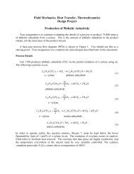
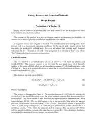
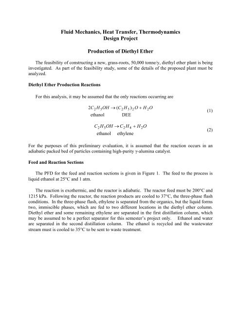
Figure 1: Unit 1200 – Diethyl Ether Production Process
3Process DetailsFeed StreamStream 1:ethanol liquid at 1 atm, 25°C – contains 70 mol% ethanol, 30 mol% waterEffluent StreamsStream 7:Stream 14:Stream 15:ethylene waste – it can be burned for credit at its LHVethylene waste – it can be burned for credit at its LHVdiethyl ether product – must have < 0.1 mol% ethyleneStream 18: Wastewater stream to treatment – must be at 35°CEquipment SummaryP-1201 A/B: Ethanol feed pumps – outlet pressure of at least 1260 kPaV-1201:E-1201:R-1201:E-1202:V-1202:E-1203:Feed drum – liquid level may vary but output remains constant – assume10 kPa pressure dropFeed preheater – reactor feed must be vapor at a minimum of 1215 kPa and200°C – assume 35 kPa pressure dropReactor – adiabatic – assume to have a pressure drop of 50 kPa – thefractional conversion of ethanol is 0.8 – the selectivity of the desired reactionto the undesired reaction is 80 moles DEE formed/mole ethylene formed –this must be simulated using a stoichiometric reactor, which only accepts onereaction – a single, overall reaction must be developed based on thestoichiometry, conversion, and selectivityProduct cooler – cools reactor outlet stream to 40°C – assume 35 kPa pressuredropThree-phase flash separator with outlet operating at a minimum of 1120 kPaand a minimum of 40°C, as long as multiple phases exists – produces anorganic-water-gas three-phase mixture that is assumed to separate easily intothree distinct streams – the VLL option must be chosen in thethermodynamics menu screen so the presence of two liquid phases iscalculated correctly<strong>Heat</strong>s column feed to 80°C – 35 kPa pressure drop
4T-1201:Distillation column – to produce diethyl ether product and ethanol for recycle– the component separator in Chemcad should be used – a perfect separatormay be assumed (which is physically impossible) for this semester only, i.e.,all diethyl ether and ethylene to the top and all ethanol and water to thebottom – the column operates at 175 kPa, with a top temperature of 46°C anda bottom temperature of 97°CIn a real distillation column, there can be feeds at different locations. Thiswill be discussed next semester. However, the component separator inChemcad only accepts one feed stream. Therefore, for this semester only,Streams 9 and 10 are to be mixed before entering the component separator.This would never occur in a realistic situation, because it makes no sense tomix streams that are already partially separated only to separate them again.While this is being done for the Chemcad simulation, the PFD should showthe more realistic physical situation.T-1202:E-1204:V-1203:Distillation column – to separate ethanol for recycle from wastewater – thecomponent separator in Chemcad should be used – 99.75% of the ethanol and9.4% of the water entering T-1202 return in the recycle stream – cannot gethigh-purity ethanol due to the azeotrope – the column operates at 170 kPawith a top temperature of 86°C and a bottom temperature of 115°CCools and partially condenses the diethyl ether product stream prior toentering V-1203, with an outlet temperature of 37°CFlash vessel allowing separation of volatile ethylene from the diethyl etherproduct streamE-1205: Cools wastewater stream to 35°CP-1202 A/B: Pumps recycle to 1260 kPaAssignmentThe first task is to obtain base-case stream flows for the process using Chemcad.The remainder of the assignment consists of five “mini-designs.”1. <strong>Fluid</strong> <strong>Mechanics</strong> (ChE 310) – Optimization of the Feed Pump and the Three-phaseFlash EffluentsPump P-1201 A/B should be sized. The optimum pipe size for Streams 6-10 should bedetermined. The objective function for the optimization is the Equivalent AnnualOperating Cost (EAOC in $/y) of the pipe in Streams 7-10 and of P-1201 A/B. TheEAOC is defined as:
5⎛ A ⎞EAOC = CAP⎜, i,n⎟+ annual operating costs for P -1201 A/B(3)⎝ P ⎠where CAP = the installed cost of P-1201 A/B and the pipe in Streams 6-10, and⎛⎜⎝( 1+)n( i)AP in ⎞ i i,, ⎟ =⎠n[ 1+ −1](4)where i = 0.15 (15% rate of return) and n = 10 (ten-year plant life).Raw-material costs or wastewater-treatment costs should not be included, so CAP onlyincludes the installed cost of pipes and pumps, and operating costs include the electricityto run the pump. The pump must supply all pressure needed prior to the distillationcolumn. It may be assumed that the pressure drop between the pump and V-1202 outletis fixed at 1260-1120 = 140 kPa. Stream 7 contains 500 m of equivalent pipe length, andthe destination pressure must be at least 1000 kPa. Stream 8 and 10 combined contain 30m of equivalent pipe length, an elevation increase of 20 m, and there is the pressure dropof 35 kPa in E-1203. Stream 9 contains 20 m of equivalent pipe length and an elevationincrease of 10 m.2. <strong>Heat</strong> <strong>Transfer</strong> (ChE 311) – <strong>Design</strong> of E-1205The heat exchanger, E-1205, must be designed in detail for the base case. Assume theinlet pressure of the process stream is the same as Stream 17. The outlet pressure mustbe specified based on the heat-exchanger design. The utility here is cooling wateravailable at 516 kPa and 30°C. The cooling water must be returned at no less than 308kPa and no hotter than 45°C. <strong>Design</strong> for no more than 35 kPa pressure drop on theprocess side. For the heat exchanger design, the following information should beprovided:• Diameter of shell• Thickness of shell wall• Number of tube and shell passes (where applicable)• Number of tubes per pass• Tube pitch and arrangement (triangular/square/..)• Number of shell-side baffles, if any, and their arrangement (spacing, pitch, type)• Tube diameter, tube-wall thickness, and length of tubes• Calculation of both shell- and tube-side film heat transfer coefficients• Calculation of overall heat transfer coefficient (it may be assumed that there is nofouling on either side of the exchanger)• Total heat-transfer area of the exchanger• Shell-side and tube-side pressure drops (calculated, not estimated)• Materials of construction for the shell and the tubes• Approximate cost of the exchanger
6• The EAOC of the heat exchanger. In Equation 3, CAP becomes the cost of the heatexchanger, and the annual operating cost is the utility cost.The maximum heat exchanger length is 6.1 m (20 ft.), and the shell diameter should bethe minimum required for the stated duty. A detailed sketch of the exchanger should beincluded along with a set of comprehensive calculations in an appendix to the minidesign.3. <strong>Thermodynamics</strong> (ChE 320) – Optimization of V-1203 and thermodynamic packageanalysisYou are to optimize the product flash, V-1203. The objective function for theoptimization should be the Equivalent Annual Operating Cost (EAOC, $/y) for thissection only, that is defined as:⎛ A ⎞EAOC = CAP⎜, i,n⎟+ AOC(5)⎝ P ⎠where CAP ($) is the capital investment for the equipment (includes any equipment thatare affected by your optimization), AOC ($/y) is the annual operating cost (includesutility costs for E-1204 as well as the reactant feed cost and product revenue).Optimization variables can include, but are not limited to the flash pressure andtemperature. The equipment and raw material costs, product value, and equipmentefficiencies are found in the Appendix.Additionally, the thermodynamics of the water-ethanol-ethylene-diethyl ether mixturethat enters the three-phase flash vessel, V-1202, must be modeled accurately.Inaccuracies in the thermodynamics of the vapor-liquid-liquid equilibrium of this mixturecan lead to inaccurate calculations of the phase separation and the overall cost of theplant. Justify your choice of thermodynamics package based on an examination of the T-xy diagrams of the pairs of components at a variety of possible operating pressures. Yourrecommendation must be based on more information than simply the Chemcad Wizard.4. Safety Analysis ReportWhen designing a chemical process, it is important to know the properties of thechemicals being consumed and produced in the process as well as the impact of anyextreme process conditions. The purpose of the safety analysis report is to makemanagement aware of risks to personnel due to extreme operating conditions as well asthe flammability and toxicity of all chemicals consumed or produced in the process. As aminimum, the SDS (safety data sheets) for all chemicals in the process should beprovided in an appendix, and a brief discussion of the major health and safety concernsfor each chemical should be given as a separate section of the report. This discussionshould include general concerns and concerns that are specific to the operating conditionsin this process. In addition, a brief discussion of possible safety hazards for each piece of
equipment in your process should be provided. Finally, an aspect of your process designthat addresses one of these safety concerns should be explained.5. Chemcad/Process ImprovementsA Chemcad simulation of the base case of the process shown in Figure 1 should beprovided. Process improvements that do not violate the laws of physics may be explored.An explanation of the rationale for such process improvements should be provided,including an economic analysis, if possible. For a process improvement involvingadditional equipment, use Equation 3, where CAP, is the cost of additional equipmentand “annual operating costs” are the savings realized (hence a negative number). This iscalled an “incremental” analysis, and the EAOC for a good process modification shouldbe negative, i.e., profitable.Other InformationIt should be assumed that a year equals 8000 hours. This is about 330 days, which allows forperiodic shutdown and maintenance.Suggested Plan of AttackThe safety analysis can begin as soon as the project is distributed. A good place to findMSDS sheets is http://siri.org. The Chemcad simulation can also be done immediately. Oncethe Chemcad simulation is done, the fluid mechanics optimization, the heat exchanger design,and the thermodynamics assignment can be completed.DeliverablesWritten ReportsEach team must deliver a report written using a word processor. Three identical copiesshould be submitted, one for each instructor, unless an electronic copy is requested by theinstructor after this document is distributed. The written project reports for all teams, regardlessof presentation date, are due by 11:00 a.m. Friday, November 30, 2012. Late projects willreceive a minimum of a one letter grade deduction.The report should be clear and concise. Guidelines are in the document entitled Written<strong>Design</strong> Reports. The report must contain a labeled process flow diagram (PFD) and a streamtable, each in the appropriate format (example will be provided). The preferred software forpreparing PFDs is Corel Draw. A PFD from Chemcad is unacceptable; however, it should beincluded in the appendix along with a Consolidated Chemcad Report for the base case. TheConsolidated Chemcad Report should contain stream compositions, but not stream properties.Figure 1 should be used as a template for your PFD. When presenting results for different cases,graphs are superior to tables. For the optimal case, the report appendix should contain details ofcalculations that are easy to follow. There should be separate appendices for each “minidesign.”These may be hand written if done neatly. Alternatively, Excel spreadsheets may beincluded, but these must be well documented with comments so that the reader can clearly7
follow your thought process and interpret the results. In either case, the calculations should beclear and all assumptions made should be explained and justified. Calculations that cannot beeasily followed and that are not explained will lose credit.Since this project involves “mini-designs,” it is suggested that the report be organized asfollows. There should be a general abstract, which summarizes the main results of the design,emphasizing what was found, not what was done. There should also be an introduction thatorients the reader to the all the mini-designs. Then, there should be a results section followed bya discussion section for each “mini-design.” A general conclusion and recommendation sectionshould follow. At a minimum, there should be one appendix for each of the “mini-designs,” withdetailed calculations that are clearly written and easy to follow.In order to evaluate each team member’s writing skills, the results and discussion sections foreach mini-design should be written by a different team member. The authorship of each of thesemini-reports should be clearly specified in the report. Although the individual written portionsof the reports must be authored by a single team member, it is the intent of the instructors thatteam members should help each other in writing different sections. To this end, it isrecommended that input be sought from your team members, including items such asproofreading and critiques.The reports will be evaluated as follows:• course-specific technical content – 50%• oral presentation – 20%• written report – 20%• technical quality of general sections (safety, simulation, etc.) – 10%For a more detailed set of evaluation criteria that we will use, see the following web site (designproject assessment, oral report assessment, written report assessment):http://www.che.cemr.wvu.edu/ugrad/outcomes/rubrics/index.phpEach report will be assessed separately by each of the three instructors. A historical accountof what each team did is neither required nor desired. Results and explanations should be thoseneeded to justify your choices, not a litany of everything that was tried. Each mini-report shouldbe limited to 4-5 double space pages plus figures and tables.Oral ReportsEach team will give an oral report in which the results of this project will be presented in aconcise manner. The oral report should be between 15-20 minutes, and each team member mustspeak. Each team member should speak only once. A 5-10 minute question-and-answer sessionwill follow, and all members must participate. Guidelines are in the document entitled OralReports. The oral presentations will be Monday, December 3, 2012, from 11:00 a.m. to 1:00p.m.; Tuesday, December 4, 2012, from 11:00 a.m. to 2:00 p.m.; and on Wednesday, December5, 2012, from 11:00 a.m. to 1:00 p.m. Attendance is required of all students during theirclassmates’ presentations (this means in the room, not in the hall or the computer room).Failure to attend any of the above-required sessions will result in a decrease of one-letter-8
grade (per occurrence) from your project grade in ChE 310, ChE 311, and ChE 320. Anyonefailing to present with his or her team is subject to a minimum one-letter-grade deductionfrom the project grade.<strong>Project</strong> ReviewThere will be a project review at 11:00 a.m. on Friday, December 7, 2012. Attendance isexpected.TeamsThis project will be completed in teams of 3 or 4. More details of team formation will bediscussed in class. There will also be peer evaluations of team members, one midway throughthe project and one after the project is submitted. These will be done on-line, and there will be awindow of time when the evaluation must be submitted. Anyone not completing either theinterim or the final peer evaluation will lose one full letter grade in the design grade for allthree classes for each evaluation not completed. The results of this evaluation may affectindividual team members’ grades, so that each team member may not receive the samegrade for the project.RevisionsAs with any open-ended problem; i.e., a problem with no single correct answer, the problemstatement above is deliberately vague. The possibility exists that, as the project proceeds,questions from the class will require revisions and/or clarifications. It is important to be awarethat these revisions/clarifications may be forthcoming.9
10Appendix 1Other Data<strong>Heat</strong> ExchangersFor heat exchangers that do not have to be designed in detail, the following approximationsmay be used for heat transfer coefficients to calculate the heat transfer area and heat exchangercost.situationh (W/m 2 °C)condensing steam 6000condensing organic 1000boiling water 7500boiling organic 2000flowing liquid 600flowing gas 60The equations for the log-mean-temperature-difference correction factor, F, for a 1-2, shelland-tubeheat exchanger are:For R ≠ 1and for R = 1where2 ⎡ 1−P ⎤R + 1ln⎢⎣1−RP⎥F =⎦⎡⎤⎢ ⎜⎛ (5)22 − P R + 1−R ⎟⎞⎥( )⎝+ 1R −1ln⎠⎢⎥⎢2− ⎜⎛ 2P R + 1+R ⎟⎞⎥⎣ ⎝+ 1⎠⎦P 2F =(6)⎡2− 2P+ P 2 ⎤( 1−P) ln⎢⎥⎣2− 2P− P 2 ⎦tout− tP =in(7)T − tininR =m&m&tubeshellCCp,tubep,shellT=tinout−T− toutin(8)
11the upper-case T is for the tube side and the lower-case t is for the shell side. It is understoodthat it does not matter which fluid is placed on which side, since the same value for F results foreither configuration.For a 2-4 shell-and-tube heat exchanger, the equations areFor R ≠ 1and for R = 12 ⎡ 1−P ⎤R + 1ln⎢⎣1−RP ⎥F =⎦(9)⎡22 − P − PR + 2 (1 − P)(1− PR)+ P R + 1⎤2( R −1)ln⎢⎥⎢2 ⎥⎣2− P − PR + 2 (1 − P)(1− PR)− P R + 1⎦P 2F =(10)⎡4(1− P)+ P 2 ⎤( − P) ln⎥⎦2 1⎢⎣4(1− P)− PFor a 3-6 shell-and-tube heat exchanger, the equations areFor R ≠ 1and for R = 1where22 ⎡ 1 − P * ⎤R + 1 ln⎢ ⎥⎣1− RP * ⎦F =⎡⎤⎢ ⎜⎛ (11)22 − P * R + 1 − R ⎟⎞⎥( )⎝+ 1⎠R − 1 ln⎢⎥⎢2− * ⎜⎛ 2P R + 1 + R ⎟⎞⎥⎣ ⎝+ 1⎠⎦P*2F =(12)⎡2− 2P*−P*2 ⎤( P*−1) ln⎢⎥⎣2− 2P* + P*2 ⎦
121 − RP1 −31 − PP*= (13)1 − RPR −31 − P
13Appendix 2Economic DataEquipment Costs (Purchased)Note: The numbers following the attribute are the minimum and maximum values for thatattribute. For a piece of equipment with a lower attribute value than the minimum, the minimumattribute value should be used to compute the cost. For a piece of equipment with a largerattribute value, extrapolation is possible, but inaccurate. To err on the side of caution, the pricefor multiple, identical, smaller pieces of equipment should be used.Pumps log (purchased cost) = 3.4 + 0.05log W + 0.15[ W ] 210 10 log10W = power (kW, 1, 300)assume 80% efficiency<strong>Heat</strong> Exchangers [ ] 2log10 (purchased cost) = 4.6 − 0.8log10A + 0.3 log10A = heat exchange area (m 2 , 20, 1000)add 25% to the purchased cost for finned tubesCompressors log (purchased cost) = 2.3 + 1.4log W − 0.1[ W ] 210 10 log10W = power (kW, 450, no limit)assume 65% efficiencyCompressor Drive log (purchased cost) = 2.5 + 1.4log W − 0.18[ W ] 210 10 log10W = power (kW, 75, 2600)all compressors require a drive in addition to the compressorTurbine log (purchased cost) = 2.5 + 1.45log W − 0.17[ W ] 210 10 log10W = power (kW, 100, 4000)assume 65% efficiencyFired <strong>Heat</strong>er [ ] 2log10 (purchased cost) = 3.0 + 0.66log10Q + 0.02 log10Q = duty (kW, 3000, 100,000)assume 80% thermal efficiencyassume can be designed to use any organic compound as a fuelVertical Vessel log (purchased cost) = 3.5 + 0.45log V + 0.11[ V ] 210 10 log10V = volume of vessel (m 3 , 0.3, 520)Horizontal Vessel log (purchased cost) = 3.5 + 0.38log V + 0.09[ V ] 210 10 log10V = volume of vessel (m 3 , 0.1, 628)AQ
14Storage Tanks log (purchased cost) = 4.85 − 0.397 log V + 0.145[ V ] 2Additional Cost Information10 10 log10V = volume of tank (m 3 , 90, 30000)Piping straight pipe: $/m = 5.0 (nominal pipe diameter, in)(1+(sch #)/20) 0.25sch = schedule number for pipeuse the same schedule number for fittings and valvesFittings (except valves) $/fitting = 50.0 (nominal pipe diameter, in)(1+(sch #)/20) 0.25Valvesfor gate (isolation) valves $100 (nominal pipe diameter, in) 0.8 (1+(sch #)/20) 0.25for control valve use $1000 (nominal pipe diameter, in) 0.8 (1+(sch #)/20) 0.25Utility CostsLow-Pressure Steam (618 kPa saturated)Medium-Pressure Steam (1135 kPa saturated)High-Pressure Steam (4237 kPa saturated)Natural Gas (446 kPa, 25°C)Fuel-gas/Off-gas CreditElectricityBoiler Feed Water (at 549 kPa, 90°C)$13.28/GJ$14.19/GJ$17.70/GJ$11.00/GJat LHV$0.06/kWh$2.45/1000 kgCooling Water$0.354/GJavailable at 516 kPa and 30°Creturn pressure ≥ 308 kPareturn temperature is no more than 15°C above the inlet temperatureRefrigerated Wateravailable at 516 kPa and 10°Creturn pressure ≥ 308 kPareturn temperature is no higher than 20°CDeionized Wateravailable at 5 bar and 30°CLow-temperature Refrigerant$4.43/GJ$1.00/1000 kg$7.89/GJ
15available at -20°CVery low-temperature Refrigerantavailable at -50°C$13.11/GJWastewater Treatment $56/1000 m 3Equipment Cost FactorsTotal Installed Cost = Purchased Cost (4 + material factor (MF) + pressure factor (PF))Pressure < 10 atm, PF = 0.0 does not apply to turbines, compressors, vessels,(absolute) 10 - 20 atm, PF = 0.6 packing, trays, or catalyst, since their cost20 - 40 atm, PF = 3.0 equations include pressure effects40 - 50 atm, PR = 5.050 - 100 atm, PF = 10100 - 200 atm, PF = 25Carbon Steel MF = 0.0Stainless Steel MF = 4.0Raw Material Costs/Product ValueRaw Material or Productethanoldiethyl etherprice1.15/kg1.70/kg