Fluid Mechanics, Heat Transfer, Thermodynamics Design Project
Fluid Mechanics, Heat Transfer, Thermodynamics Design Project
Fluid Mechanics, Heat Transfer, Thermodynamics Design Project

You also want an ePaper? Increase the reach of your titles
YUMPU automatically turns print PDFs into web optimized ePapers that Google loves.
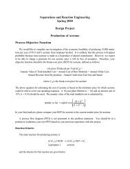
<strong>Fluid</strong> <strong>Mechanics</strong>, <strong>Heat</strong> <strong>Transfer</strong>, <strong>Thermodynamics</strong><strong>Design</strong> <strong>Project</strong>Production of AmmoniaYour assignment is to continue evaluating the details of a process to produce 50,000 tonne/yof ammonia from a syngas feed. This is the amount of ammonia in the product stream, not thetotal mass of the product stream.A base-case process flow diagram (PFD) is shown in Figure 1. You should use this as astarting point. Your assignment is to complete the mini-designs described later in this document.Chemical ReactionSyngas is available from a pipeline at 1000 kPa and 200°C. It is mixed with a recyclestream, compressed, and heated or cooled to 350°C to be fed to the reactor. The reactor operatesadiabatically. The reactor effluent is cooled, the pressure is reduced by a valve, resulting inpartial condensation, producing an ammonia-rich liquid stream. The ammonia liquid product isin Stream 10. Some of Stream 11 is recycled and some is purged.The reaction that occurs in the reactor is reversibleN + 3 = NH(1)2 H 2 2This is an equilibrium reaction, and the equilibrium constant over a wide range of temperatures isgiven by3K= 3.29 × 10⁻¹²exp⎡11,806⎤⎢⎣ T ⎥⎦(2)The units of K are atm -2 . In the reactor, there is a 10°C approach to equilibrium.Process DetailsFeed Stream and Effluent StreamsStream 1: syngas – at 200°C and 1000 kPa – contains 72 mol% H 2 , 24 mol% N 2 , and4 mol% CH 4Stream 10: ammonia product – 50,000 tonne/y – a year is 8000 hoursStream 12: purge used as fuel-gas to furnace – there is no credit for this stream
Base-Case Equipment InformationCompressors (C-601/C-602)These compress the feed to a sufficient pressure so that the reactor inlet is at 15,000 kPa.The compressor consists of two stages with identical compression ratios. The compressorsare adiabatic with a 65% efficiency.<strong>Heat</strong> Exchanger (E-601)This is an intercooler, cooling the feed stream to 50°C using cooling water. The pressuredrop is 35 kPa. Since compressors do not get along well with liquids, both the feed and exitof this heat exchanger must be 100% vapor.<strong>Heat</strong> Exchanger (E-602)This heat exchanger heats or cools the reactor feed to 350°C. The pressure drop is 35 kPa.Reactor (R-601)This is an adiabatic, packed bed reactor. The inlet pressure is 15,000 kPa. This reactorshould be simulated on Chemcad using the equilibrium reactor module. The pressure unitmust be specified as atm. The approach to equilibrium is 10°C, and the pressure drop is 50kPa.<strong>Heat</strong> Exchanger (E-603)This heat exchanger cools and partially condenses the reactor effluent. The base-caseeffluent temperature is 15°C, and refrigerated water is used. The pressure drop is 35 kPa.The subsequent valve reduces the pressure entering the flash to 1050 kPa.Vessel (V-601)This vessel separates the light gases from ammonia at the conditions of Stream 9. Thepressure drop across the vessel is 25 kPa, which allows an additional 25 kPa of pressure dropfor the recycle stream. This vessel should be simulated on Chemcad as a flash separator withmode zero. The vapor exits in the top stream, and the liquid exits in the bottom stream.Assume a 10-minute liquid residence time for sizing considerations. This means that theflowrate of the liquid stream exiting in Stream 10 is used to calculate a volume. Then, thisvolume is doubled to allow space for the vapor to disengage from the liquid. If you need todetermine the cost of this vessel, assume it is a vertical vessel. The subsequent recycle/purgeratio is 9/1 in the base case.
For E-601, which will be designed in detail, the approximate pressure drops may be used inthe calculations to determine optimal pipe diameter. However, in the detailed heat exchangerdesign, the pressure drops must be calculated using the appropriate relationships.In order to evaluate the amount and cost of piping required for the mini-design, it may beassumed that C-601, E-601, and C-602 are at grade (ground level). C-601 is located 3 m ofequivalent length from the mixing point for Streams 1 and 13 with the mixing point 1 m abovegrade. The suction line for each compressor is 0.5 m above grade, and the discharge line foreach compressor is 1.5 m above grade. The equivalent length of the pipe for Stream 2 is 3 m, theequivalent length of the pipe for Stream 3 is 4 m, the equivalent length of the pipe for Stream 4 is2 m, and the equivalent length of Stream 5 is 3 m. For this mini-design only, both E-601 and E-602 may be assumed to be horizontal, 1-2 exchangers, with the feed 1.5 m above grade and thedischarge 0.5 m above grade2. <strong>Heat</strong> <strong>Transfer</strong> – (ChE 311)<strong>Design</strong> of <strong>Heat</strong> Exchanger, E-601A detailed design of E-601 is required for base-case conditions. It should be assumed thatcooling water is available at the conditions specified in the Appendix of this problem statement.For this heat exchanger design, the following information should be provided:• Diameter of shell• Number of tube and shell passes• Number of tubes per pass• Tube pitch and arrangement (triangular/square/..)• Number of shell-side baffles, if any, and their arrangement (spacing, pitch, type)• Diameter, tube-wall thickness, shell-wall thickness, and length of tubes• Calculation of both shell- and tube-side film heat transfer coefficients• Calculation of overall heat transfer coefficient (you may assume that there is nofouling on either side of the exchanger)• <strong>Heat</strong> transfer area of the exchanger• Shell-side and tube-side pressure drops (calculated, not estimated)• Materials of construction• Approximate cost of the exchangerA detailed sketch of the exchanger should be included along with a set of comprehensivecalculations in an appendix to the mini-design.3. <strong>Thermodynamics</strong> – (ChE 320)You are to optimize the flash and recycle system, which includes Streams 8, 9, 11, 12, and 13along with C-601/602, E-601, and V-601. The objective function for the optimization should bethe Equivalent Annual Operating Cost (EAOC, $/y) for this section only, that is defined as:
⎛ A ⎞EAOC = CAP⎜, i,n⎟+ AOC(2)⎝ P ⎠where CAP ($) is the capital investment for the equipment (includes compressors, heatexchangers, vessel, etc.), AOC ($/y) is the annual operating cost (includes utility costs forcompressor as well as the reactant feed cost), and⎛⎜⎝( 1+)n( i)AP in ⎞ i i,, ⎟ =⎠n[ 1+ −1](3)where i = 0.15 (15% rate of return) and n = 10 (ten-year plant life). Optimization variables caninclude, but are not limited to the vessel pressure and temperature, and the recycle-to-purge ratio.The equipment and raw material costs, product value, and equipment efficiencies are found inthe Appendix.Additionally, the thermodynamics of the ammonia-nitrogen-hydrogen-methane mixture thatenters the flash vessel must be modeled accurately. Inaccuracies in the thermodynamics of thevapor-liquid equilibrium of this mixture can lead to inaccurate calculations of the phaseseparation and the overall cost of the plant. Justify your choice of thermodynamics packagebased on an examination of the T-xy diagrams of the pairs of components at a variety of possibleoperating pressures.4. Safety Analysis ReportWhen designing a chemical process, it is important to know the properties of the chemicalsbeing consumed and produced in the process as well as the impact of any extreme processconditions. There is significant documentation of safety practices in ammonia plants. Thepurpose of the safety analysis report is to make management aware of risks to personnel due toextreme operating conditions as well as the flammability and toxicity of all chemicals consumedor produced in the process. As a minimum, the MSDS (material and safety data sheets) for allthese chemicals should be provided in an appendix, and a brief discussion of the major concernsfor each chemical should be given as a separate section of the report. This discussion shouldinclude general concerns and concerns that are specific to the operating conditions in thisprocess. In addition, a brief discussion of possible safety hazards for each piece of equipment inyour process should be provided. Finally, a feature of your process design that addresses one ofthese concerns should be explained.5. Chemcad/Process ImprovementsA Chemcad simulation of the base case of the process shown in Figure 1 should be provided.Process improvements that do not violate the laws of physics may be suggested. An explanationof the rationale for such process improvements should be provided, including an economicanalysis, if possible. Since there is no reactor cost available at this time, it may be omitted fromany economic analysis. Since the reactor is effectively a constant, the optimum is not affected,but the EAOC is off by a constant value.
Other InformationIt should be assumed that a year equals 8000 hours. This is about 330 days, which allows forperiodic shutdown and maintenance.Suggested Plan of AttackThe safety analysis can begin as soon as the project is distributed. A good place to findMSDS sheets is http://siri.org. The Chemcad simulation can also be done immediately. Oncethe Chemcad simulation is done, the heat exchanger can be designed. The fluidmechanics/thermodynamics design and the thermodynamics design can be completed next. Thevapor-liquid equilibrium analysis should not be attempted until that material is covered inthermodynamics class.DeliverablesWritten ReportsEach group must deliver a report written using a word processor. Three identical copiesshould be submitted, one for each instructor. The written project reports for all groups,regardless of presentation date, are due by 11:00 a.m. Thursday, December 3, 2009. Late projectswill receive a minimum of a one letter grade deduction.The report should be clear and concise. For the correct formatting information, refer to thedocument entitled Written <strong>Design</strong> Reports. The report must contain a labeled process flowdiagram (PFD) and a stream table, each in the appropriate format. The preferred software forpreparing PFDs is Corel Draw. A PFD from Chemcad is unacceptable; however, it should beincluded in the appendix along with a Chemcad report for the base case. Figure 1 should be usedas a template for your PFD. When presenting results for different cases, graphs are superior totables. For the optimal case, the report appendix should contain details of calculations that areeasy to follow. There should be separate appendices for each “mini-project.” These may behand written if done neatly. Alternatively, Excel spreadsheets may be included, but these mustbe well documented so that the reader can interpret the results. Calculations that cannot be easilyfollowed and that are not explained will lose credit.Since this project involves “mini-designs,” it is suggested that the report be organized asfollows. There should be a general abstract, which summarizes the results of your work,emphasizing what you found, not what you did. There should also be an introduction, whichorients the reader to the problem. Then, there should be a results section followed by adiscussion section for each “mini-design.” General conclusion and recommendation sectionsshould follow. At a minimum, there should be one appendix for each of the “mini-designs” withdetailed calculations that are clearly written and easy to follow.In order to evaluate each group member’s writing skills, the results and discussion sectionsfor each mini-design should be written by a different group member. The authorship of each of
these mini-reports should be clearly specified in the report. Although the individual writtenportions of the reports must be authored by a single group member, it is the intent of theinstructors that group members should help each other in writing different sections. To this end,we recommend that you seek input, such as proofreading and critiques, from other members ofyour group.The reports will be evaluated as follows:• course-specific technical content – 50%• oral presentation – 20%• written report – 20%• technical quality of general sections (safety, simulation, etc.) – 10%For a more detailed set of evaluation criteria that we will use, see the following web site (designproject assessment, oral report assessment, written report assessment):http://www.che.cemr.wvu.edu/ugrad/outcomes/rubrics/index.phpEach report will be assessed separately by each of the three instructors. A historical accountof what each group did is neither required nor wanted. Results and explanations should be thoseneeded to justify your choices, not a litany of everything that was tried. Each mini-report shouldbe limited to 4-5 double space pages plus figures and tables.Oral ReportsEach group will give an oral report in which the results of this project will be presented in aconcise manner. The oral report should be between 15-20 minutes, and each group membermust speak. Each group member should speak only once. A 5-10 minute question-and-answersession will follow, and all members must participate. Refer to the document entitled OralReports for instructions. The oral presentations will be Thursday, December 3, 2008, from 11:00a.m. to 2:00 p.m. and on Friday, December 4, 2009, from 11:00 a.m. to 1:00 p.m. Attendance isrequired of all students during their classmates’ presentations (this means in the room, not in thehall or the computer room). Failure to attend any of the above-required sessions will result ina decrease of one-letter-grade (per occurrence) from your project grade in ChE 310, ChE 311,and ChE 320. Anyone failing to present with his or her group is subject to a minimum oneletter-gradededuction from the project grade.<strong>Project</strong> ReviewThere will be a project review at 11:00 a.m. on Friday, December 11, 2009. Attendance isexpected.TeamsThis project will be completed in teams of 3 or 4. More details of group formation and peerevaluation will be discussed in class.
RevisionsAs with any open-ended problem; i.e., a problem with no single correct answer, the problemstatement above is deliberately vague. The possibility exists that, as the project proceeds,questions from the class will require revisions and/or clarifications. It is important to be awarethat these revisions/clarifications may be forthcoming.
AppendixEconomic DataEquipment Costs (Purchased)Note: The numbers following the attribute are the minimum and maximum values for thatattribute. For a piece of equipment with a lower attribute value than the minimum, the minimumattribute value should be used to compute the cost. For a piece of equipment with a largerattribute value, extrapolation is possible, but inaccurate. To err on the side of caution, the pricefor multiple, identical, smaller pieces of equipment should be used.Pumps log (purchased cost) = 3.4 + 0.05log W + 0.15[ W ] 210 10 log10W = power (kW, 1, 300)assume 80% efficiency<strong>Heat</strong> Exchangers log (purchased cost) = 4.6 − 0.8log A + 0.3[ A] 210 10 log10A = heat exchange area (m 2 , 20, 1000)Compressors log (purchased cost) = 2.3 + 1.4log W − 0.1[ W ] 210 10 log10W = power (kW, 450, no limit)assume 65% efficiencyCompressor Drive log (purchased cost) = 2.5 + 1.4log W − 0.18[ W ] 210 10 log10W = power (kW, 75, 2600)Turbine log (purchased cost) = 2.5 + 1.45log W − 0.17[ W ] 210 10 log10W = power (kW, 100, 4000)assume 65% efficiencyFired <strong>Heat</strong>er log (purchased cost) = 3.0 + 0.66log Q + 0.02[ Q] 210 10 log10Q = duty (kW, 3000, 100,000)assume 80% thermal efficiencyassume can be designed to use any organic compound as a fuelVertical Vessel log (purchased cost) = 3.5 + 0.45log V + 0.11[ V ] 210 10 log10V = volume of vessel (m 3 , 0.3, 520)Horizontal Vessel log (purchased cost) = 3.5 + 0.38log V + 0.09[ V ] 210 10 log10V = volume of vessel (m 3 , 0.1, 628)Storage Tanks log (purchased cost) = 4.85 − 0.397log V + 0.145[ V ] 210 10 log10V = volume of tank (m 3 , 90, 30000)
Additional Cost InformationPiping straight pipe: $/m = 5.0 (nominal pipe diameter, in)(1+(sch #)/20) 0.25sch = schedule number for pipeuse the same schedule number for fittings and valvesFittings (except valves) $/fitting = 50.0 (nominal pipe diameter, in)(1+(sch #)/20) 0.25Valvesfor gate (isolation) valves $100 (nominal pipe diameter, in) 0.8 (1+(sch #)/20) 0.25for control valve use $1000 (nominal pipe diameter, in) 0.8 (1+(sch #)/20) 0.25Utility CostsLow-Pressure Steam (618 kPa saturated)Medium-Pressure Steam (1135 kPa saturated)High-Pressure Steam (4237 kPa saturated)Natural Gas (446 kPa, 25°C)Fuel Gas CreditElectricityBoiler Feed Water (at 549 kPa, 90°C)$13.28/GJ$14.19/GJ$17.70/GJ$11.00/GJnone, but there is no treatment cost$0.06/kWh$2.45/1000 kgCooling Water$0.354/GJavailable at 516 kPa and 30°Creturn pressure ≥ 308 kPareturn temperature is no more than 15°C above the inlet temperatureRefrigerated Wateravailable at 516 kPa and 10°Creturn pressure ≥ 308 kPareturn temperature is no higher than 20°CDeionized Wateravailable at 5 bar and 30°CWaste Treatment of Off-GasLow-temperature Refrigerantavailable at -20°C$4.43/GJ$1.00/1000 kgincinerated – zero cost$7.89/GJ
Very low-temperature Refrigerant $13.11/GJavailable at -50°CWastewater Treatment $56/1000 m 3Raw Material Costs/Product ValueRaw Material or Productsyngasammoniaprice$0.10/kg$500/tonneEquipment Cost FactorsTotal Installed Cost = Purchased Cost (4 + material factor (MF) + pressure factor (PF))Pressure < 10 atm, PF = 0.0 does not apply to turbines, compressors, vessels,(absolute) 10 - 20 atm, PF = 0.6 packing, trays, or catalyst, since their cost20 - 40 atm, PF = 3.0 equations include pressure effects40 - 50 atm, PR = 5.050 - 100 atm, PF = 10100 - 200 atm, PF = 25Carbon Steel MF = 0.0Stainless Steel MF = 4.0