Dynamic Characteristics of Check Valves - Val-Matic Valve and ...
Dynamic Characteristics of Check Valves - Val-Matic Valve and ...
Dynamic Characteristics of Check Valves - Val-Matic Valve and ...

Create successful ePaper yourself
Turn your PDF publications into a flip-book with our unique Google optimized e-Paper software.
®<strong>Dynamic</strong> <strong>Characteristics</strong><strong>of</strong> <strong>Check</strong> <strong><strong>Val</strong>ves</strong>VAL-MATIC VALVE AND MANUFACTURING CORP.905 RIVERSIDE DRIVE, ELMHURST, IL 60126TEL. (630) 941-7600 FAX. (630) 941-8042www.valmatic.comCopyright © 2008 <strong>Val</strong>-<strong>Matic</strong> <strong>Val</strong>ve <strong>and</strong> Manufacturing Corp.
FOREWORD<strong>Dynamic</strong> <strong>Characteristics</strong> <strong>of</strong> <strong>Check</strong> <strong><strong>Val</strong>ves</strong> was written to assist the design pr<strong>of</strong>essional in predictingslam in basic check valves without dashpots <strong>and</strong> other specialized hydraulic controls. It is notintended to provide all <strong>of</strong> the information necessary for selecting a check valve but rather to explainin engineering terms the cause <strong>of</strong> check valve slam <strong>and</strong> the inherent closing characteristics <strong>of</strong> variouscheck valves that contribute to this phenomenon.With this knowledge, the design pr<strong>of</strong>essional can predict before pump station start-up whetherserious check valve problems will occur. Other design issues such as head loss <strong>and</strong> cost are equallyimportant factors <strong>and</strong> should be considered in making the final valve selection.The test data presented <strong>of</strong>fers valuable information for predicting valve performance. It is based onindependent tests conducted at the Utah Water Research Laboratory <strong>and</strong> remains the property <strong>of</strong><strong>Val</strong>-<strong>Matic</strong> <strong>Val</strong>ve & Mfg. Corp. Any use <strong>of</strong> this information in other public disclosures requireswritten permission from <strong>Val</strong>-<strong>Matic</strong>.<strong>Val</strong>-<strong>Matic</strong> <strong>of</strong>fers no warranty or representation as to the accuracy or completeness <strong>of</strong> these graphs.Use <strong>of</strong> these graphs should be made under the direction <strong>of</strong> trained engineers or design pr<strong>of</strong>essionalsexercising independent judgment regarding the suggested use <strong>of</strong> the valves in fluid systems.1
DYNAMIC CHARACTERISTICS OF CHECK VALVESINTRODUCTIONWhen bringing a pump station on line for the first time, the design engineer has manyconcerns such as when the START button is pressed, will the pump produce the rated flow <strong>and</strong> whenthe STOP button is pressed, will the check valve slam. <strong>Check</strong> valve slam can range from a minornuisance to a building-shaking, neighborhood-disturbing crash. These types <strong>of</strong> problems can delayapproval <strong>of</strong> projects for months; therefore, check valve slam warrants careful study <strong>and</strong>underst<strong>and</strong>ing.<strong>Check</strong> valve characteristics have been extensively studied in Europe for many years. It hasonly been in recent years that check valve manufacturers in the United States have tested thedynamic characteristics <strong>of</strong> their valve designs <strong>and</strong> provided this data to design pr<strong>of</strong>essionals. <strong>Val</strong>-<strong>Matic</strong> has completed an exhaustive testing program on several types <strong>of</strong> basic check valves <strong>and</strong>published this data in the form <strong>of</strong> dynamic response curves. The term “basic” refers to a check valvewithout oil dashpots <strong>and</strong> other devices that significantly slow down the closure <strong>of</strong> the valve <strong>and</strong>intentionally allow reverse flow to pass through the check valve.A new methodology will be explained to generate check valve response data <strong>and</strong> predictcheck valve slam in any application. This is a tall order, but it is hoped that this methodology willbe a good starting point so that when it is combined with field experience over the coming years, aproven valve selection methodology can be adopted by the water <strong>and</strong> wastewater industries.CHECK VALVE SELECTIONThere are several technical papers, valve h<strong>and</strong>books, <strong>and</strong> s<strong>of</strong>tware design tools available toassist in check valve selection. The process is <strong>of</strong>ten difficult because selecting a check valve caninvolve many criteria such as non-slamming characteristics, headloss characteristics, operating costs,controllability, maintenance costs, <strong>and</strong> installation laying length. Most <strong>of</strong> these criteria however, arestraightforward <strong>and</strong> can be calculated for the various types <strong>of</strong> check valves available. Thismethodology will focus on non-slamming characteristics <strong>and</strong> matching them to various systems. Itis a fact that given a severe pumping application, all basic check valves will slam. It is also a factthat in some applications no check valve will slam. It is the unpredictability <strong>of</strong> the middle groundbetween these extremes that makes the task <strong>of</strong> selecting check valves difficult.<strong>Check</strong> valve slam occurs after pump stoppage when the system flow reverses back towardsthe pump before the check valve is fully closed. The reverse flow causes the check valve to closerapidly through the remaining portion <strong>of</strong> its travel. The reverse flow is then stopped instantaneouslyby the closed valve causing a sometimes loud water hammer in the pipe. The noise associated withthe slam is not the impact <strong>of</strong> the disc into the seat, but2
ather the rapid stretching <strong>of</strong> the pipe due to the water hammer. Surprisingly, a resilient-seatedcheck valve can make the same metallic slam sound as a metal-seated valve.To prevent check valve slam, a check valve must either close very rapidly before appreciablereverse flow occurs or very slowly once reverse-flow has developed (L<strong>and</strong>on, 32). In order to closerapidly, studies (Thorley, 180) indicate that:● the disc should have low inertia <strong>and</strong> friction,● the travel <strong>of</strong> the disc should be short, or● the motion should be assisted with springs.To close slowly, a check valve needs to be equipped with external devices such as oil dashpots <strong>and</strong>the pump must be capable <strong>of</strong> withst<strong>and</strong>ing some backspin. Dashpot devices have proven to beeffective, but are beyond the scope <strong>of</strong> this methodology. The answer to preventing check valve slamis not to find the fastest closing check valve <strong>and</strong> make it the “st<strong>and</strong>ard”. Instead, the non-slamcharacteristics <strong>of</strong> the check valve must be matched with the pumping system. Every check valve hasinherent advantages such as low cost, low headloss, or special flow characteristics. The best checkvalve is not necessarily the one with the least potential to slam.Probably the simplest pumping system is a water well application consisting <strong>of</strong> a singlepump operating at low pressure <strong>and</strong> sending water to a ground reservoir several thous<strong>and</strong> feetdistant. Because <strong>of</strong> the low operating pressure <strong>and</strong> high friction, after pump stoppage the flow willreverse or decelerate slowly. The rate at which the flow reverses, however, is important in gaugingwhether the check valve will slam. For a low head application with a long pipe length, there is lesspotential for rapid flow reversal <strong>and</strong> the simplest <strong>and</strong> lowest cost check valve may be used withoutslamming. On the other h<strong>and</strong>, a multiple-pump station sending water to a high head system with anearby elevated or pneumatic surge tank will experience an extremely rapid flow reversal <strong>and</strong> onlycertain check valves can be used without slamming.To select a non-slam check valve, the pump station designer must first analyze the pumpingsystem <strong>and</strong> calculate the deceleration <strong>of</strong> the liquid column after pump stoppage. In other words, ifthe flow rate is 12 ft/sec <strong>and</strong> calculations show that the flow will stop in 2 seconds, then the averagedeceleration is 12 ft/sec divided by 2 sec or 6.0 ft/sec 2 . Calculating the deceleration can be difficultbecause it is a function <strong>of</strong> many parameters such as pump inertia (provided by the pumpmanufacturer), length <strong>of</strong> the liquid column, friction losses in the piping system, <strong>and</strong> the static head orslope <strong>of</strong> the pipe. Engineers typically rely on a computer simulation <strong>of</strong> the system to computedeceleration.It is the responsibility <strong>of</strong> the valve manufacturer to provide the dynamic characteristics <strong>of</strong>their valves so that the engineer can predict the maximum reverse velocity that may occur. It issuggested that for each type <strong>of</strong> check valve, a response curve should be generated to show therelationship between the deceleration <strong>of</strong> the liquid column <strong>and</strong> the maximum reverse velocitythrough the check valve (Provoost, 278). The deceleration is expressed in terms <strong>of</strong> dv/dt or changein forward velocity divided by change in time or ft/sec 2 . The reverse velocity is developed fromtesting <strong>and</strong> is expressed in velocity terms or ft/sec.3
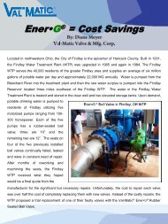
For example, dynamic test data for a dual-plate wafer check valve is shown in Figure 1. Thehorizontal axis represents the deceleration <strong>of</strong> the piping system expressed in feet per second squared.The vertical axis is the maximum reverse velocity through the check valve expressed in feet persecond. A single-pump, low-head system will have a deceleration <strong>of</strong> less than 20 ft/sec 2 . A highheadsystem <strong>of</strong> a multiple-pump system may have a deceleration as high as 40 ft/sec 2 . For thishigher deceleration, the dual plate check valve <strong>of</strong> Figure 1 will allow a reverse velocity to developequal to about 1.0 ft/sec. The reverse velocity can be converted directly into water hammer pressureusing the equation [AWWA, 51]:a vh =gWhere: h = pressure rise, ft <strong>of</strong> watera = wave velocity, ft/sec ≈ 3200 ft/sec (steel pipe)v = reverse velocity, ft/secg = 32.2 ft ft/sec 2The reverse flow <strong>of</strong> 1.0 ft/sec corresponds to a water hammer <strong>of</strong> 100 ft (43 psi). Fieldexperience shows that water hammers in the range <strong>of</strong> 50 to 100 ft (or reverse velocities <strong>of</strong> 0.5 to 1.0ft/sec) represent a mild slam <strong>and</strong> can be tolerated. Conversely, water hammers over 100 ft (orreverse velocities over 1.0 ft/sec) are extremely loud <strong>and</strong> should be avoided by either selecting adifferent check valve or modifying the check valve with heavier springs or hydraulic dashpots.<strong>Dynamic</strong> <strong>Characteristics</strong> <strong>of</strong> Dual Plate <strong>Check</strong> <strong><strong>Val</strong>ves</strong>Reverse Velocity, ft/sec2.01.81.61.41.21.00.80.60.40.20.00 10 20 30 40 50 60Deceleration, ft/sec 2Figure 1. <strong>Dynamic</strong> Test Data4
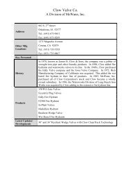
TEST METHODOLOGYTo develop dynamic characteristics for its check valves, <strong>Val</strong>-<strong>Matic</strong> contracted a series <strong>of</strong>valve flow tests at the Utah Water Research Laboratory in Logan, Utah. Several types <strong>of</strong> eight-inchcheck valves were water flow tested under dynamic conditions.The check valves were installed in a horizontal test piping run <strong>and</strong> subjected to differentinitial forward flows <strong>and</strong> varying rates <strong>of</strong> flow reversals. The lab is supplied with a natural supply <strong>of</strong>mountain run<strong>of</strong>f water from a reservoir through a 48 in. pipeline so velocities in the range <strong>of</strong> four totwenty feet per second were easily attained. The lab is also equipped with a certified weigh tanksystem to record flow rates. <strong>Val</strong>ve head loss was read using manometers <strong>and</strong> dynamic pressureswere recorded using transducers <strong>and</strong> a high-speed data recorder.<strong>Check</strong> <strong>Val</strong>vePres. TransducerMain <strong>Val</strong>veSecondary PumpFigure 2. <strong>Check</strong> <strong>Val</strong>ve Test LoopForward flow from the reservoir was established by opening the Main <strong>Val</strong>ve shown in Figure2. The supply flow at about 5 psig from the reservoir automatically opened the check valve fully<strong>and</strong> flow rates <strong>and</strong> headloss data were recorded. Next, a secondary pump was started to supplyadditional flow at a higher pressure <strong>of</strong> about 20 psig. Both flows merged downstream <strong>of</strong> the checkvalve <strong>and</strong> exited through the Main <strong>Val</strong>ve.To trigger a check valve slam, the Main <strong>Val</strong>ve was suddenly closed stopping the forwardflow <strong>and</strong> the secondary pump would rapidly produce reverse flow <strong>and</strong> valve slam. Different rates <strong>of</strong>deceleration were achieved by closing the Main <strong>Val</strong>ve at different rates.5
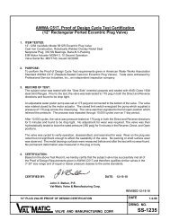
The pressure downstream <strong>of</strong> the valve was recorded <strong>and</strong> used to calculate the deceleration <strong>of</strong>the flow <strong>and</strong> the reverse velocity through the valve. A sample computer trace is shown in Fig. 3.PRESSUREDSLAM PRESSUREMAIN VALVECLOSUREBEACCHECK VALVE SLAMTIMEFigure 3. Sample Pressure RecordingThe sequence associated with Figure 3 above is as follows:A = reservoir pressureA-B = main valve is closed stopping forward flow, check valve starts to closeB = flow is stopped, check valve continues to closeB-C = reverse flow buildsC = valve disc strikes the seat causing slam <strong>and</strong> water hammerD = water hammer pressure resulting from sudden reverse flow stoppageE = secondary pump pressureAverage decelerations were calculated by dividing the initial velocity by the A-B time interval. Thereverse flow velocity was calculated based on the surge pressure measured between points C <strong>and</strong> D<strong>and</strong> the equation given on page 4.6
This test methodology has been applied by different researchers to many types <strong>of</strong> check valves.For example, Thorley (p. 23) tested <strong>and</strong> reported results for common ball check <strong>and</strong> swing checkvalves as shown in Figures 4 <strong>and</strong> 5. Provoost tested nozzle check valves in similar fashion as shownin Figure 6.Figure 4. Ball <strong>Check</strong> Figure 5. Swing <strong>Check</strong> Figure 6. Nozzle <strong>Check</strong>The test methodology was applied to five 8-inch flanged <strong>Val</strong>-<strong>Matic</strong> production check valves asshown in Figures 7 through 11 (Rahmeyer):Figure 7. <strong>Val</strong>-<strong>Matic</strong> Model 508Swing-Flex® <strong>Check</strong> <strong>Val</strong>ve (SFCV).The SFCV features a resilient hinged disc,angled seat, <strong>and</strong> short stroke.Figure 8. <strong>Val</strong>-<strong>Matic</strong> Model 9808 Tilted Disc ®<strong>Check</strong> <strong>Val</strong>ve (TDCV).This valve features an <strong>of</strong>fset butterfly type disc,angled seat, short stroke, <strong>and</strong> 140% port areafor the lowest possible headloss.7
Figure 9. Model 8808 Dual Disc®<strong>Check</strong> <strong>Val</strong>ve (DDCV).The DDCV features two half-circle discsthat pivot closed with the assistance <strong>of</strong> astrong torsion spring.Figure 10. Model 7208 Surgebuster ® Swing<strong>Check</strong> <strong>Val</strong>ve (SB).The Surgebuster ® (SB) features a resilient hingeddisc, angled seat, <strong>and</strong> short stroke, <strong>and</strong> a discaccelerator.Figure 11. Model 1808 Globe-StyleSilent <strong>Check</strong> <strong>Val</strong>ve (SCV).The SCV features a short linear strokewith a strong return spring.8
TEST RESULTSThe test results for these valves are presented in graph form in Figure 12 together withsimilar data for swing check <strong>and</strong> ball check valves (Thorley, 23) <strong>and</strong> nozzle check valves (Provoost,283). The results clearly indicate that the best non-slam check valves are the Nozzle <strong>Check</strong> <strong>Val</strong>ve,Dual Disc <strong>Check</strong> <strong>Val</strong>ve (DDCV), SurgeBuster, <strong>and</strong> the Silent <strong>Check</strong> <strong>Val</strong>ve (SCV) which all featurespring-assisted closure. The next best non-slam check valves are the Swing-Flex ® <strong>Check</strong> <strong>Val</strong>ve(SFCV) <strong>and</strong> Tilted Disc ® <strong>Check</strong> <strong>Val</strong>ve (TDCV), which feature an angled seat <strong>and</strong> short stroke.Finally, the valves with long strokes <strong>and</strong> no spring assist, the ball check <strong>and</strong> swing check, have thegreatest potential for slamming.Figure 12. <strong>Dynamic</strong> <strong>Characteristics</strong> <strong>of</strong> Various <strong>Check</strong> <strong><strong>Val</strong>ves</strong>The chart was divided into three ranges: NO SLAM, MILD SLAM, <strong>and</strong> SEVERE SLAM.These divisions are based on numerous field observations <strong>of</strong> valve slams <strong>and</strong> acceptable levels <strong>of</strong>noise <strong>and</strong> disturbance to the valve <strong>and</strong> pumping system. The designer can also convert the givenreverse velocity to a quantitative surge pressure using the equation on page 4 <strong>and</strong> make a separatedetermination <strong>of</strong> system impact.9
The designer uses Figure 12 by finding the system deceleration on the horizontal axis <strong>and</strong>then reading the reverse velocity for the various types <strong>of</strong> check valves. For example, given amultiple pump station with a calculated system deceleration is 30 ft/sec 2 , the following predictionscan be read from the graph:VALVE TYPE REVERSE VELOCITY TYPE OF SLAMSilent <strong>Check</strong> (SCV) .33 ft/sec noneSurgebuster Swing <strong>Check</strong> (SB) .44 ft/sec noneNozzle <strong>Check</strong> <strong>Val</strong>ve .60 ft/sec mildDual Disc <strong>Check</strong> (DDCV) .60 ft/sec mildTilted Disc <strong>Check</strong> (TDCV) .80 ft/sec mildSwing-Flex <strong>Check</strong> (SFCV) 1.8 ft/sec severeBall <strong>Check</strong> (BALL) >2.0 ft/sec severeSwing <strong>Check</strong> (SWING) >2.0 ft/sec severeThe designer can go on to calculate an estimated slam pressure on the basis that there isabout 100 ft <strong>of</strong> water hammer for every 1 ft/sec <strong>of</strong> reverse velocity. In the example above, theSurgebuster (SB) would produce a slam pressure <strong>of</strong> about 0.44 x 100 or a 44 ft (19 psi) pressuresurge, which would sound like a dull thud upon closure.However, the designer can still consider using one <strong>of</strong> the valves in the “mild” or “severe”slam ranges by possibly changing to a speed-controlled pump or modifying the valve to include astronger spring or an oil dashpot. At first glance, it may seem impractical to do so, but acharacteristic <strong>of</strong> one <strong>of</strong> the valves such as the low headloss <strong>of</strong> a Tilted Disc ® <strong>Check</strong> <strong>Val</strong>ve may beimportant for this application <strong>and</strong> an oil dashpot could be economically justified.Finally, it is important to note some limitations <strong>of</strong> using the dynamic characteristic datapresented in Figure 11. First, the test data is based on installation in a horizontal pipeline. Somevalves rely on gravity to accelerate disc closure such as the SWING, TDCV, <strong>and</strong> SFCV valves <strong>and</strong>when installed in a vertical pipe, may have a greater tendency to slam. Conversely, other valvessuch as the DDCV <strong>and</strong> the SCV will close faster in a vertical line due to gravity effects on their discs<strong>and</strong> have a lesser tendency to slam. Also, the dynamic characteristics <strong>of</strong> the valve are dependent onvalve size but no data is available at this time to predict the exact effect <strong>of</strong> size. Larger valves haveheavier discs <strong>and</strong> longer strokes <strong>and</strong> will likely produce somewhat higher reverse velocities thanpredicted from Figure 12. The manufacturer should be consulted for the potential impact <strong>of</strong>orientation <strong>and</strong> size on the performance <strong>of</strong> the selected valve.10
CONCLUSIONIt should be clear that dynamic characteristic data for check valves only <strong>of</strong>fers the designerthe tools necessary to evaluate the non-slam characteristics <strong>of</strong> various check valves. Thisinformation, combined with other readily available valve characteristics such as headloss, layinglength, waterway design for fluids containing solids, <strong>and</strong> cost will provide the designer with all <strong>of</strong>the tools necessary to make reliable valve selections.REFERENCES1. American Water Works Association, (1989). Steel Pipe Manual M11, 3rd edition, Denver, CO,51-56.2. Ballun, John V., (2007). A Methodology for Predicting <strong>Check</strong> <strong>Val</strong>ve Slam, Journal AWWA,March 2007, 60-65.3. Provoost, G.A., (1983). A critical analysis to determine dynamic characteristics <strong>of</strong> non-returnvalves, Proceedings <strong>of</strong> the 4th International Conference on Pressure Surges, Bath Engl<strong>and</strong>, 275-286.4. Rahmeyer, William, (1998). Reverse flow testing <strong>of</strong> eight-inch <strong>Val</strong>-<strong>Matic</strong> check valves, UtahState University Lab Report No. USU-609, <strong>Val</strong>-<strong>Matic</strong> <strong>Val</strong>ve Test Report No. 117, Elmhurst, IL,[CONFIDENTIAL].5. Thorley, A.R.D., (1991). Fluid Transients in Pipeline Systems, D&L George Ltd, Hadley Wood,Engl<strong>and</strong>, 22-23.6. Thorley, A.R.D. (1989), <strong>Check</strong> valve behavior under transient flow conditions: a state-<strong>of</strong>-the-artreview. Journal <strong>of</strong> Fluids Engineering 111, 178-183, Fairfield, NJ.11