CCPV-OM2 - Val-Matic Valve and Manufacturing Corp.
CCPV-OM2 - Val-Matic Valve and Manufacturing Corp.
CCPV-OM2 - Val-Matic Valve and Manufacturing Corp.

Create successful ePaper yourself
Turn your PDF publications into a flip-book with our unique Google optimized e-Paper software.
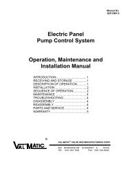
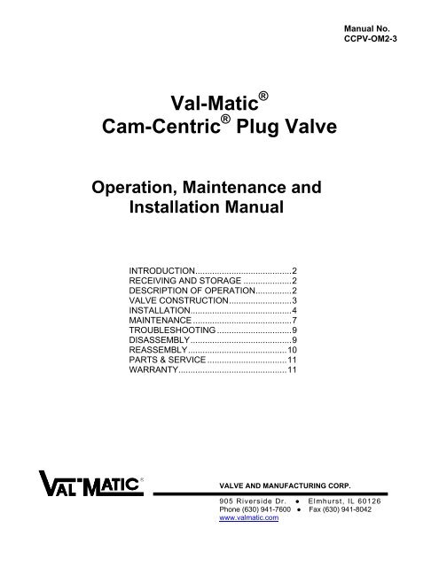
Manual No.<strong>CCPV</strong>-<strong>OM2</strong>-3<strong>Val</strong>-<strong>Matic</strong> ®Cam-Centric ® Plug <strong>Val</strong>veOperation, Maintenance <strong>and</strong>Installation ManualINTRODUCTION ........................................ 2RECEIVING AND STORAGE .................... 2DESCRIPTION OF OPERATION ............... 2VALVE CONSTRUCTION .......................... 3INSTALLATION .......................................... 4MAINTENANCE ......................................... 7TROUBLESHOOTING ............................... 9DISASSEMBLY .......................................... 9REASSEMBLY ......................................... 10PARTS & SERVICE ................................. 11WARRANTY ............................................. 11VALVE AND MANUFACTURING CORP.905 Riverside Dr. ● Elmhurst, IL 60126Phone (630) 941-7600 ● Fax (630) 941-8042www.valmatic.com
VAL-MATIC'S CAM-CENTRIC PLUG VALVEOPERATION, MAINTENANCE AND INSTALLATIONINTRODUCTIONThe Cam-Centric Plug <strong>Val</strong>ve has been designed togive years of trouble-free operation. This manual willprovide you with the information to properly install <strong>and</strong>maintain the valve to ensure a long service life. Thevalve is an eccentric, resilient seated, quarter-turn plugvalve capable of h<strong>and</strong>ling many types of fluidsincluding fluids with suspended solids. The Size,Cold Working Pressure (CWP), Actuator Rating, <strong>and</strong>Model No. are stamped on the nameplate forreference.CAUTION: Do not use valve for line testing atpressures higher than nameplate rating orleakage <strong>and</strong> damage to valve may occur.The "Cold Working Pressure" is the non-shockpressure rating of the valve at 150 o F. The valve is notintended as a block valve for line testing above thevalve rating. The “Actuator Rating” is the pressure thatwas used to size the actuator for operating conditions<strong>and</strong> may be less than the “Cold Working Pressure”.Because the valve is eccentric, the valve may have adifferent actuator rating for reverse <strong>and</strong> direct pressure.If the valve is operated at pressures higher than theactuator ratings, the valve may be difficult to operate orleak.RECEIVING AND STORAGEInspect valves upon receipt for damage in shipment.Unload all valves carefully to the ground withoutdropping. Do not lift valves with slings or chainsaround the actuator or through the seat area.FIGURE 1. PLUG VALVE WITH GEAR ACTUATORThe eccentric offset causes the plug to lift <strong>and</strong> rotateoff the seat simultaneously to reduce seat friction <strong>and</strong>wear during operation. Direct Pressure pushes theplug into the seat <strong>and</strong> Reverse Pressure pushes theplug away from the seat. The valve can be operatedwith a direct nut, lever, or gear actuator. The gearactuator as shown in Figure 1 requires multi-turn inputon a 2” square nut, h<strong>and</strong>wheel, or chainwheel. Thevalve can also be automated with power actuatorssuch as an electric motor or hydraulic cylinder.<strong>Val</strong>ves should remain crated, clean <strong>and</strong> dry untilinstalled to prevent weather-related damage. For longterm storage greater than six months, the valve mustremain open <strong>and</strong> the rubber surfaces of the plugcoated with a thin film of FDA approved grease suchas Dow Corning # 7. Do not expose plug to sunlight orozone for any extended period.DESCRIPTION OF OPERATIONAs shown in Figure 2, the valve consists of a body <strong>and</strong>quarter-turn plug that is offset from the seat centerline.FIGURE 2. PLUG VALVE TERMS2
VALVE CONSTRUCTIONThe st<strong>and</strong>ard Cam-Centric ® Plug <strong>Val</strong>ve is constructedof rugged cast iron with a welded nickel seat <strong>and</strong>permanently lubricated bearings. See the specificMaterials List submitted for the order if other thanst<strong>and</strong>ard cast iron construction. The details ofconstruction are illustrated in Figure 3.The body (1) is available with flanged or mechanicaljoint ends for connection to the pipeline. The valve isdesigned to be serviced in-line by removing the castcover (2). The quarter-turn plug (3) is guided by sleevebearings (6) located in the cover <strong>and</strong> lower boss in thebody. Grit-Guard seals (21) are located at the bottomof the bearings (6) to prevent abrasive material fromwearing the bearing. Leak-tight closure is made whenthe rubber-coated plug (3) is rotated into the nickelseat on the “SEAT END” of the body.ITEM DESCRIPTION MATERIAL1 Body Cast Iron with OverlayWelded Nickel Seat2 Cover Cast Iron3 Plug* Cast Iron withResilient Facing6 Bearings* 316 Stainless Steel7 V-Type Packing* Buna-N8 Cover Seal* Buna-N15 Cover Bolt Alloy Steel, Gr 518 Packing Follower Cast Iron19 Follower Bolt Alloy Steel, Gr. 521 Grit-Guard* Buna-N22 Thrust Bearing* Teflon23 Thrust Bearing* 316 Stainless Steel24 Key Carbon Steel29 Shims 304 Stainless Steel*RECOMMENDED SPARE PARTTABLE 1. STANDARD PLUG VALVE PARTS LISTFIGURE 3. STANDARD PLUG VALVE CONSTRUCTION3
INSTALLATIONThe installation of the valve is important for its properoperation. The valve is capable of flow in eitherdirection but the maximum operating pressure can varywith the location of the seat end. The words “SEATEND” are marked on the valve flange. Actuators areavailable for pressures up to the full rating in bothdirect <strong>and</strong> reverse pressure orientations. Actuatorratings will be indicated on the nameplate. Higheroperating pressures may require adjustment of theclosed position stop or a larger actuator; consult thefactory.FIGURE 4. HORIZONTAL PIPE WITH SOLIDSSUSPENDED SOLIDS SERVICE: For fluidscontaining suspended solids, special orientations areneeded to prevent debris from collecting in the valve.For horizontal installations (Figure 4), the valve shouldbe installed with the flow entering the seat end of thevalve <strong>and</strong> the shaft in a horizontal position with theplug up when open. For vertical installations (Figure5), the valve must be installed with the seat end upregardless of flow direction.CLEAN SERVICE: For both horizontal <strong>and</strong> verticalinstallations, install in the direct pressure orientation(pressure opposite the seat end).AIR AND GAS SERVICE: Install valve in the directpressure orientation (pressure opposite the seat end).Lubricate plug face with FDA approved silicone greasesuch as Dow Corning #7 before installation. Gearactuators are required for gas service applications.FIGURE 5. VERTICAL PIPE WITH SOLIDSPUMP DISCHARGE SERVICE: On all horizontalpump discharge applications (Figure 6), the seat endshould be towards the pump.BURIED SERVICE: Gear actuators are recommendedfor buried valves to hold the valve in position <strong>and</strong>provide multi-turn closure to prevent water hammer.The valve should be installed with the shaft horizontal<strong>and</strong> the actuator nut directed upwards. The valve boxor extension pipe should be installed so that theactuator nut <strong>and</strong> extension stem turn freely.NOTE: Adjust <strong>and</strong> test valve prior to backfill.FIGURE 6. PUMP DISCHARGE SERVICE4
FLANGED ENDS: Flanged valves should be matedwith flat-faced pipe flanges equipped with resilientgaskets. When ring gaskets are used, the bolt materialshould be ASTM A307 Grade B of SAE Grade 2Carbon Steel. Higher strength bolts may only be usedwith full-face gaskets.Place lubricated gasket <strong>and</strong> retainer gl<strong>and</strong> over pipeend prior to installing valve. Install valve socket overpipe. Press gl<strong>and</strong> <strong>and</strong> gasket toward valve until gasketis evenly set into valve socket.The valve <strong>and</strong> adjacent piping must be supported <strong>and</strong>aligned to prevent cantilevered stress on the valve.Lower valve into line using slings or chains around thevalve body. Lubricate the flange bolts or studs <strong>and</strong>insert them around the flange. Lightly turn bolts untilgaps are eliminated.The torquing of the bolts should then be done ingraduated steps using the cross-over tighteningmethod. Recommended lubricated torques for usewith resilient gaskets (75 durometer) are given in Table2. If leakage occurs, allow gaskets to absorb fluid <strong>and</strong>check torque <strong>and</strong> leakage after 24 hours. Do notexceed bolt rating or crush gasket more than 50percent of its thickness.VALVE BOLT RECOM MAXSIZE DIA TORQUE TORQUE(in) (in) (ft-lbs) (ft-lbs)3 5/8 25 904 5/8 30 906 3/4 30 1508 3/4 40 15010 7/8 45 20512 7/8 65 20514 1 80 30016 1 90 30018 1 1/8 100 42520 1 1/8 120 42524 1 1/4 150 60030 1 1/4 175 60036 1 1/2 175 100042 1 1/2 200 100048 1 1/2 250 1000TABLE 2. FLANGE BOLT TORQUESCAUTION: The use of raised-face flangesor excessive bolt torque maydamage valve flanges.FIGURE 7. MECHANICAL JOINT INSTALLATIONInsert T-bolts in valve flange <strong>and</strong> h<strong>and</strong> tighten nuts.Torque nuts in four graduated steps using the crossovertightening method without exceeding the torquelisted in Table 3. Maintain an equal gap between thegl<strong>and</strong> <strong>and</strong> the face of the valve at all points around thesocket.If a tight connection is not achieved, then the jointshould be disassembled, thoroughly cleaned, <strong>and</strong>reassembled. Over-tightening may cause damage tothe valve or gl<strong>and</strong>.VALVE T-BOLT RECOM MAXSIZE DIA TORQUE TORQUE(in) (in) (ft-lbs) (ft-lbs)3 5/8 45 604 3/4 75 906 3/4 75 908 3/4 75 9010 3/4 75 9012 3/4 75 9014 3/4 75 9016 3/4 75 9018 3/4 75 9020 3/4 75 9024 3/4 75 9030 1 100 12036 1 100 12042 1-1/4 75 15048 1-1/4 75 150MECHANICAL JOINT ENDS: Clean ends of matingpipe <strong>and</strong> valve sockets with soapy water (Figure 7).5TABLE 3. MECHANICAL JOINT NUT TORQUES
DIRECT NUT OPERATED VALVES: 8” <strong>and</strong> smallervalves may be equipped with a top-mounted nut fordirect quarter-turn operation. The nut is 2” square to fitmost valve wrenches <strong>and</strong> is mounted directly to thevalve plug. To open the valve, slowly rotate the nut 90degrees in the counter-clockwise (CCW) direction. Theclosed position is adjusted with a set screw <strong>and</strong> locknut, see Figure 8. The open position can be adjustedby moving the bolt along the curved slot.LEVER OPERATED VALVES: A wrench head <strong>and</strong>lever (Figure 10) are available for use over the 2” nutfor direct quarter-turn operation. Various lever lengthsare available for specific direct <strong>and</strong> reverse pressureconditions as shown in Table 4.WRENCH LENGTH, (Inches)VALVE DIRECT PRES. REVERSE PRES.SIZE 100 psi 175 psi 50 psi 175 psi2 1/2 22 22 22 223 22 22 22 224 22 22 22 226 44 * 44 *8 44 * 44 **Worm gear recommended due to operating torqueTABLE 4. APPLICATION OF LEVERSFIGURE 8. DIRECT NUT ADJUSTMENTSDIRECT NUT FRICTION ADJUSTMENT: As shownin Figure 9, valves with direct nut actuators have aflanged packing follower (18) above the packing (7)to hold the valve in the open or closed position. If thevalve is difficult to operate or does not maintain itsset position, adjust the clamp bolt (17) to providesufficient friction to hold the valve in position. IF thevalve is equipped with a h<strong>and</strong> lever, the settingshould allow the valve to be operated with about 80pounds of force on the end of the pipe h<strong>and</strong>le.FIGURE 10. HANDLEVERThe wrench head is placed over the nut <strong>and</strong> can besecured with the set screw provided. To open thevalve, rotate the lever 90 degrees in the CCWdirection. The closed position is adjustable with a setscrew <strong>and</strong> lock nut mounted below the nut, see Figure8.CAUTION: Open <strong>and</strong> close the valve slowly toprevent water hammer.FIGURE 9. FRICTION ADJUSTMENTGEAR OPERATED VALVES: 4” <strong>and</strong> larger plugvalves are available with a multi-turn manual gearactuator. The gear unit has a self-locking worm gearwhich multiplies the turning force on the h<strong>and</strong>wheel ornut so that the valve can be operated with ease. Aclamp-on chainwheel kit can also be used forinstallations high above the floor. An indicator on thetop of the actuator housing indicates the position of thevalve plug. The h<strong>and</strong>wheel or nut must be rotatedthrough 12-80 turns (depending on model) to open orclose the plug valve. The direction of rotation to openthe valve is indicated on the 2” square actuator nut.6
GEAR ACTUATOR ADJUSTMENT: The st<strong>and</strong>ardgear actuator is provided with factory-set open <strong>and</strong>closed position stops. If the valve does not shut offtight, the stop bolt can be adjusted allowing the plug torotate further into the seat. Loosen the locknut, <strong>and</strong>turn the closed stop bolt CCW 1 turn at a time (Figure11). If the valve continues to leak after all of theadjustment is taken verify the orientation of the valveduring installation. If a tight shut-off can not beachieved, a larger gear actuator may be required forthe system operating pressure; consult the factory.CAUTION: Adjust closed stop bolt for tightshut-off only. Over adjustmentmay cause high operating torques<strong>and</strong> damage to the plug.CLOSED POSITION ADJUSTMENT: The st<strong>and</strong>ardvalve is factory-set to seal at the “Actuator PressureRatings” shown on the nameplate for direct <strong>and</strong>reverse pressure directions (see Figure 2). Higherpressure applications may require adjustment of theclosed position stop or a larger actuator; consult thefactory.If the valve is found to leak in the closed position dueto wear, the plug can be adjusted by loosening theclosed position stop on the actuator <strong>and</strong> rotating theplug further into the seat. Because of the eccentricaction of the valve, further rotation will provideadditional interference between the rubber plug surface<strong>and</strong> the body seat. <strong>Val</strong>ves that have been in servicefor several years may require inspection of the plug fordamage or wear. See the Disassembly Instructions ofthis manual.PACKING ADJUSTMENT: V-type packing is pressuresensitive <strong>and</strong> therefore self-adjusting in nature. Overtightening will destroy both the pressure sensitivenature of the packing as well as its sealing capabilities.The packing configuration used in Cam-Centric Plug<strong>Val</strong>ves follows the guidelines <strong>and</strong> recommendations ofV-packing manufacturers.FIGURE 11: GEAR ACTUATOR ADJUSTMENTAdditional adjustment can be achieved by removingone or more shims found under the packing follower(18). If a leak develops, remove one shim (29) fromthe underside of the follower (18). An equal number ofshims must be removed from both the left <strong>and</strong> righth<strong>and</strong> sides. Re-tighten the follower bolts (19) <strong>and</strong>check for leakage. If the leakage continues, removeadditional shims or replace the packing.MAINTENANCEThe Cam Centric ® Plug <strong>Val</strong>ve requires no scheduledlubrication or maintenance other than regularexercising <strong>and</strong> occasional inspection of the plug. Theexercising is achieved by fully opening <strong>and</strong> closing thevalve to verify smooth operation. If operation isdifficult, it may be necessary to flush sediment from thevalve by opening <strong>and</strong> closing the valve several timesunder flowing conditions.CAUTION: Open <strong>and</strong> close the valve slowly toprevent water hammer.FIGURE 12. PACKING ASSEMBLYThe recommended interval for exercising is every sixmonths or annually if the valve is regularly operated.Over the life of the valve, inspection <strong>and</strong> some regularadjustments may be needed as given below.7
PACKING REPLACEMENT: To replace the packing(7), it is recommended that the line be drained <strong>and</strong> theactuator removed. The valve can remain in the line. Tereplace the packing, first open the valve <strong>and</strong> drain theline. Close the valve to hold it in position. For poweractuators, turn off <strong>and</strong> lock out electrical <strong>and</strong> hydraulicsupplies before proceeding.CAUTION: Drain line <strong>and</strong> close valve beforeremoving actuator or valve mayrotate suddenly. Take precautionsagainst exposure to toxic orhazardous fluids in the line.Remove the small round cover on actuator to exposeshaft <strong>and</strong> key. Remove actuator mounting bolts <strong>and</strong> liftactuator from valve taking care not to lose square key.See Figure 12 <strong>and</strong> remove gl<strong>and</strong> bolts (19) <strong>and</strong> liftfollower (18) from the valve shaft. Remove old packing(7) with packing hook. Lubricate new packing withFDA grease <strong>and</strong> set in place one ring at a time takingcare not to bend over the lips of the packing rings.Reinstall follower with 2 shims (29) per bolt (3 shimsfor 12” <strong>and</strong> larger valves). With valve in the closedposition, place the actuator over valve <strong>and</strong> reinsert key(24). Finally, reinstall cover on actuator indicating“Closed”.GEAR ACTUATOR MAINTENANCE: A typical gearactuator is shown in Figure 13 <strong>and</strong> consists of a worm(3) mounted on an input shaft (9). The worm engagesa worm wheel (2). When the worm is turned, it drivesthe wheel through 90 of rotation. The rotation of thevalve plug is displayed by the top indicator (5). Theopen <strong>and</strong> closed positions of the segment gear arecontrolled by an end position stop bolts (20). Thestops can be adjusted by loosening the lock nut (21)<strong>and</strong> rotating the bolts. The gears are lubricated withEP2 grease in a cast iron housing (1). Other parts arelisted in Table 5.The gear box is factory lubricated <strong>and</strong> sealed. Noregular maintenance is required. If difficult operation isobserved, the cover (4) can be removed <strong>and</strong> the unitinspected for wear. All moving parts should be coatedwith grease. The grease should have an even <strong>and</strong>smooth consistency. If needed, coat all moving partswith an lithium-based EP-2 grease such as ShellAlvania #2 or equal. Buried units should be packed90% with grease.CAUTION: If packing assembly containsclamp style follower as shown inFigure 8, do not lubricate shaft orsleeve.PACKING REPLACEMENT WITH ACTUATOR: Theabove procedure with removal of the actuator will resultin the most reliable shaft seal. But if the actuator cannot be removed, the following alternate procedure canbe followed. To prevent the possibility of leakageduring this procedure, open valve <strong>and</strong> drain the line.CAUTION: Take precautions againstexposure to toxic or hazardousfluids in the line.Referring to Figure 12, remove follower bolts (19) <strong>and</strong>side follower (18) up to actuator. Remove packingadapters <strong>and</strong> rings (7) with packing hook. Cut ringswith knife to remove. New packing rings should be cutat a 45 degree slope to allow insertion around the shaft<strong>and</strong> provide some overlap. Install rings one at a timewith the tips down toward the valve. Stagger all joints180 degrees around the shaft. Pull down follower (18)<strong>and</strong> reinsert bolts (19) with 2 shims (29) under follower(18). V-packing is pressure assisted <strong>and</strong> only requireslight compression.FIGURE 13. GEAR ACTUATOR CONSTRUCTION8
ITEM DESCRIPTION MATERIAL1 Housing Cast Iron2 Wormwheel Ductile Iron3 Worm Steel4 Cover Cast Iron5 Indicator Cast Iron6 O-Ring Buna-N7 Roller Bearing Steel8 Shaft Bearing Bronze9 Shaft Steel10 Gasket Fiber11 H<strong>and</strong>wheel Steel or Iron12 Operating Nut Iron13 Chainwheel Iron14 Cover Bolt Steel15 Indicator Bolt Steel16 Pipe Plug Steel17 Pin Steel18 Spirol Pin Steel19 Spring Pin Steel20 Screw Steel21 Jam Nut Steel22 Plug Steel23 U-Cup Seal Buna-NTABLE 5. GEAR ACTUATOR PARTS LISTTROUBLESHOOTINGSeveral problems <strong>and</strong> solutions are presented below toassist you in troubleshooting the valve assembly in anefficient manner.• Leakage at <strong>Val</strong>ve Shaft: Adjust or replace packing.• Leakage at Flanges: Tighten flange bolts, replacegasket.• <strong>Val</strong>ve Leaks when Closed: Pressure should be in thedirection of pushing the plug into the seat. Adjustplug position by rotating the h<strong>and</strong>wheel. Inspect plugfor damage <strong>and</strong> replace.• Hard to Open: Flush debris from valve. Checkinterior of valve for grit buildup or debris. On buriedvalves, check alignment of operating stem.• Leaking Oil: Tighten actuator cover bolts. If leakpersists, remove actuator cover, inspect grease, <strong>and</strong>replace actuator gasket.• Noisy Operation: Flow noise is normal. Loud flownoise similar to hammering may be cavitation fromdropping high pressures across valve; reviewapplication of valve. For gear actuator noise, inspectgrease; add new grease if there are uncoatedmoving parts or grease has broken down into oil.DISASSEMBLYDisassembly may be required to inspect the plug forwear or remove debris <strong>and</strong> deposits from the valve.Work on the valve should be performed by a skilledmechanic with proper tools <strong>and</strong> a power hoist for largevalves. The valve can be disassembled withoutremoving the valve from the pipeline. Refer to Figure14 for valve construction <strong>and</strong> parts.WARNING: Open valve <strong>and</strong> drain line beforeremoving cover bolts or pressuremay be released causing injury.Place plug in lowest positionbefore removing actuator or plugmay rotate suddenly <strong>and</strong> jam ordamage plug surface.1. Open valve <strong>and</strong> drain the pipeline. Close valveuntil plug just touches the seat. Remove the smallcover on the actuator to expose the shaft key.2. Remove the actuator mounting bolts <strong>and</strong> liftactuator from valve taking care not to lose key(24).3. Remove cover bolts (15). Matchmark cover (2)<strong>and</strong> body. Screw eye-bolts into actuator mountingholes <strong>and</strong> use hoist to lift cover (2) <strong>and</strong> plugassembly from valve. Use caution to prevent plugfrom dropping while lifting cover. To remove plug(3) from valve, use sling around top portion ofplug.4. Inspection of the bearings (6) is done bymeasuring diameter of shaft <strong>and</strong> inside diameter ofbearing. Check for a normal running clearance of.005". Bearings are permanently lubricated.5. Thrust bearing assembly (23) <strong>and</strong> packing gl<strong>and</strong>(18) can be removed by removing all of the hexnuts (12).9
REASSEMBLYAll parts must be cleaned <strong>and</strong> gasket surfaces shouldbe cleaned with a stiff wire brush in the direction of theserrations or machine marks. Worn parts, gaskets <strong>and</strong>seals should be replaced during reassembly.3. Apply thin film of FDA silicone grease such asDow Corning #7 to plug rubber surface. Placestainless steel thrust bearing (23) over lower endof plug, Teflon bearing (22) over the upper end.Install grit seals (21) over the shafts of the plug.4. Carefully place plug into the body (1) <strong>and</strong> insertlower plug shaft into bottom bearing (6). Plug (3)should be in the open position. Install cover (2)over plug shaft <strong>and</strong> into recess in body. Alignmatch marks between body <strong>and</strong> cover (2). Torquecover bolts (15) per Table 6 in 3-4 incrementsusing the cross-over tightening method.SIZETORQUE (FT-LBS)1/2"-13 45 - 755/8"-11 100 - 1503/4"-10 150 - 2507/8"-9 200 - 3501"-8 300 - 5001 1/8"-7 450 - 7001 1/4"-7 650 - 10001 1/2"-6 750 - 1100TABLE 6. TIGHTENING TORQUES5. Lubricate ID <strong>and</strong> OD of packing set with FDAgrease <strong>and</strong> install in packing bore one ring at atime taking care to keep lips pointing down towardplug. Reinstall follower, gl<strong>and</strong> bolts, <strong>and</strong> 2 shimsper bolt.NOTE: If valve has friction assembly with directnut actuator, follow Friction Adjustment procedureon page 6.6. Insert key (24) into shaft <strong>and</strong> place actuator overvalve. Reinstall actuator mounting bolts <strong>and</strong>torque per Table 6. Install cover on actuator.FIGURE 14. PLUG VALVE PARTS1. Press new bearings (6) into cover <strong>and</strong> body withround, flat bar 1/4" below inside surfaces of body(1) <strong>and</strong> cover (2).7. Apply power to actuator <strong>and</strong> cycle valve. Applypressure to valve <strong>and</strong> check for cover <strong>and</strong> shaftleakage. Tighten bolts as necessary. Adjustpacking if necessary.8. If valve does not shut off tight, adjust the closedposition stop as described on page 6 under“Closed Position Adjustment.”2. Install cover seal (8) over cover lip.
PARTS AND SERVICEParts <strong>and</strong> service are available from your localrepresentative or the factory. Make note of the valveSize, Series No, <strong>and</strong> Serial No. located on the valvenameplate <strong>and</strong> contact:<strong>Val</strong>-<strong>Matic</strong> <strong>Val</strong>ve <strong>and</strong> Mfg. <strong>Corp</strong>.905 Riverside DriveElmhurst, IL 60126PH: 630/941-7600FAX: 630/941-8042A sales representative will quote prices for parts orarrange for service as needed.LIMITED WARRANTYAll products are warranted to be free of defects in material <strong>and</strong> workmanship for a period of one year from the date of shipment,subject to the limitations below.If the purchaser believes a product is defective, the purchaser shall: (a) Notify the manufacturer, state the alleged defect <strong>and</strong>request permission to return the product; (b) if permission is given, return the product with transportation prepaid. If the productis accepted for return <strong>and</strong> found to be defective, the manufacturer will, at his discretion, either repair or replace the product,f.o.b. factory, within 60 days of receipt, or refund the purchase price. Other than to repair, replace or refund as describedabove, purchaser agrees that manufacturer shall not be liable for any loss, costs, expenses or damages of any kind arising outof the product, its use, installation or replacement, labeling, instructions, information or technical data of any kind, description ofproduct use, sample or model, warnings or lack of any of the foregoing. NO OTHER WARRANTIES, WRITTEN OR ORAL,EXPRESS OR IMPLIED, INCLUDING THE WARRANTIES OF FITNESS FOR A PARTICULAR PURPOSE ANDMERCHANTABILITY, ARE MADE OR AUTHORIZED. NO AFFIRMATION OF FACT, PROMISE, DESCRIPTION OFPRODUCT OF USE OR SAMPLE OR MODEL SHALL CREATE ANY WARRANTY FROM MANUFACTURER, UNLESSSIGNED BY THE PRESIDENT OF THE MANUFACTURER. These products are not manufactured, sold or intended forpersonal, family or household purposes.VALVE AND MANUFACTURING CORP.905 Riverside Dr. ● Elmhurst, IL 60126Phone (630) 941-7600 ● Fax (630) 941-8042www.valmatic.com