BMS Buttress Systems - Vibro/Dynamics Corporation
BMS Buttress Systems - Vibro/Dynamics Corporation
BMS Buttress Systems - Vibro/Dynamics Corporation

You also want an ePaper? Increase the reach of your titles
YUMPU automatically turns print PDFs into web optimized ePapers that Google loves.
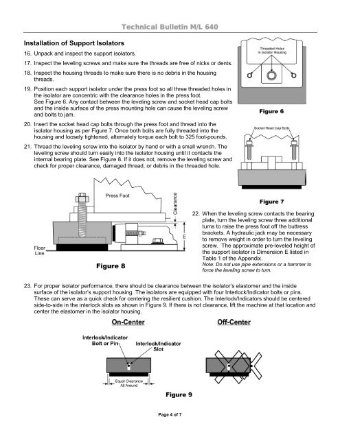
Installation of Support Isolators16. Unpack and inspect the support isolators.Technical Bulletin M/L 64017. Inspect the leveling screws and make sure the threads are free of nicks or dents.18. Inspect the housing threads to make sure there is no debris in the housingthreads.19. Position each support isolator under the press foot so all three threaded holes inthe isolator are concentric with the clearance holes in the press foot.See Figure 6. Any contact between the leveling screw and socket head cap boltsand the inside surface of the press mounting hole can cause the leveling screwand bolts to jam.20. Insert the socket head cap bolts through the press foot and thread into theisolator housing as per Figure 7. Once both bolts are fully threaded into thehousing and loosely tightened, alternately torque each bolt to 325 foot-pounds.21. Thread the leveling screw into the isolator by hand or with a small wrench. Theleveling screw should turn easily into the isolator housing until it contacts theinternal bearing plate. See Figure 8. If it does not, remove the leveling screw andcheck for proper clearance, damaged thread, or debris in the threaded hole.22. When the leveling screw contacts the bearingplate, turn the leveling screw three additionalturns to raise the press foot off the buttressbrackets. A hydraulic jack may be necessaryto remove weight in order to turn the levelingscrew. The approximate pre-leveled height ofthe support isolator is Dimension E listed inTable 1 of the Appendix.Note: Do not use pipe extensions or a hammer toforce the leveling screw to turn.23. For proper isolator performance, there should be clearance between the isolator’s elastomer and the insidesurface of the isolator’s support housing. The isolators are equipped with four Interlock/Indicator bolts or pins.These can serve as a quick check for centering the resilient cushion. The Interlock/Indicators should be centeredside-to-side in the interlock slots as shown in Figure 9. If there is not clearance, lift the machine at that location andcenter the elastomer in the isolator housing.Page 4 of 7