Smart DialTM Controller User's Guide - Irritrol
Smart DialTM Controller User's Guide - Irritrol
Smart DialTM Controller User's Guide - Irritrol
- No tags were found...

Create successful ePaper yourself
Turn your PDF publications into a flip-book with our unique Google optimized e-Paper software.
User Programmed–ET Service Inactive Mode . . . . . . . . . . . . . . . .31Station Program Off Mode . . . . . . . . . . . . . . . . . . . . . . . . . . . . . . .32Control Features . . . . . . . . . . . . . . . . . . . . . . . . . . . . . . . . . . . . . . .32Copy Feature . . . . . . . . . . . . . . . . . . . . . . . . . . . . . . . . . . . . . . . . . . .32Copy from Station to Station(s) . . . . . . . . . . . . . . . . . . . . . . . . . . . . .32Restore <strong>Controller</strong> Default Values . . . . . . . . . . . . . . . . . . . . . . . . . . .33Restore Program Defaults . . . . . . . . . . . . . . . . . . . . . . . . . . . . . . .33Restore Schedule or Setup Defaults . . . . . . . . . . . . . . . . . . . . . . .34Review Feature . . . . . . . . . . . . . . . . . . . . . . . . . . . . . . . . . . . . . . . . . .34% Adjust Feature . . . . . . . . . . . . . . . . . . . . . . . . . . . . . . . . . . . . . . . .36ET Feature . . . . . . . . . . . . . . . . . . . . . . . . . . . . . . . . . . . . . . . . . . . . . .38Review Current ET Values . . . . . . . . . . . . . . . . . . . . . . . . . . . . . . . . .38Adjust Custom Turf and Plant Kc Values . . . . . . . . . . . . . . . . . . . . . .38Operating Modes and Features . . . . . . . . . . . . . . . . . . . . . . . . . . .39Run Mode . . . . . . . . . . . . . . . . . . . . . . . . . . . . . . . . . . . . . . . . . . . . . .39Manual Mode . . . . . . . . . . . . . . . . . . . . . . . . . . . . . . . . . . . . . . . . . . .39Specific Station Operation . . . . . . . . . . . . . . . . . . . . . . . . . . . . . . . .39Sequential Station Operation . . . . . . . . . . . . . . . . . . . . . . . . . . . . . .40Rain Pause Mode . . . . . . . . . . . . . . . . . . . . . . . . . . . . . . . . . . . . . . . .41Off Mode – <strong>Controller</strong> Shutdown . . . . . . . . . . . . . . . . . . . . . . . . . . . .42System Alerts . . . . . . . . . . . . . . . . . . . . . . . . . . . . . . . . . . . . . . . . . . .42Alert Status . . . . . . . . . . . . . . . . . . . . . . . . . . . . . . . . . . . . . . . . . .42Water Window Status . . . . . . . . . . . . . . . . . . . . . . . . . . . . . . . . . .43Day Status . . . . . . . . . . . . . . . . . . . . . . . . . . . . . . . . . . . . . . . . . .43Communication Status . . . . . . . . . . . . . . . . . . . . . . . . . . . . . . . . .43Electrical Status . . . . . . . . . . . . . . . . . . . . . . . . . . . . . . . . . . . . . . .43v
System Help . . . . . . . . . . . . . . . . . . . . . . . . . . . . . . . . . . . . . . . . . . . .44Current Weekly ET . . . . . . . . . . . . . . . . . . . . . . . . . . . . . . . . . . . . . .44Serial Number . . . . . . . . . . . . . . . . . . . . . . . . . . . . . . . . . . . . . . . . . .44Microzone . . . . . . . . . . . . . . . . . . . . . . . . . . . . . . . . . . . . . . . . . . . .44Data Encryption Mask . . . . . . . . . . . . . . . . . . . . . . . . . . . . . . . . . . .44Start Times (First Irrigation and High ET Start) . . . . . . . . . . . . . . . . .44Beep on Message? (Yes/No) . . . . . . . . . . . . . . . . . . . . . . . . . . . . . . .44Phase Integrity . . . . . . . . . . . . . . . . . . . . . . . . . . . . . . . . . . . . . . . . .44Lock Phase . . . . . . . . . . . . . . . . . . . . . . . . . . . . . . . . . . . . . . . . . . .44Reset/Erase or Restart . . . . . . . . . . . . . . . . . . . . . . . . . . . . . . . . . . .44Installation Procedures . . . . . . . . . . . . . . . . . . . . . . . . . . . . . . . . . .45Installing the <strong>Controller</strong> . . . . . . . . . . . . . . . . . . . . . . . . . . . . . . . . . . .45Connecting the Control Valves . . . . . . . . . . . . . . . . . . . . . . . . . . . . .46Connecting a Rain Sensor (optional) . . . . . . . . . . . . . . . . . . . . . . . . .47Connecting the Indoor Model Power Source andEarth Ground for Indoor and Outdoor Models . . . . . . . . . . . . . . . . . .48Connecting the Outdoor Model Power Source . . . . . . . . . . . . . . . . .49Installing an External Antenna (optional) . . . . . . . . . . . . . . . . . . . . . .50Display Contrast Adjust . . . . . . . . . . . . . . . . . . . . . . . . . . . . . . . . .50Appendix A: Acquiring Sprinkler Precipitation Rate . . . . . . . . .51Appendix B: Troubleshooting . . . . . . . . . . . . . . . . . . . . . . . . . . . . .53Appendix C: Glossary of Terms . . . . . . . . . . . . . . . . . . . . . . . . . . .56Fuse Replacement . . . . . . . . . . . . . . . . . . . . . . . . . . . . . . . . . . . . . .58Specifications . . . . . . . . . . . . . . . . . . . . . . . . . . . . . . . . . . . . . . . . . .59FCC Compliance Information . . . . . . . . . . . . . . . . . . . . . . . . . . . .59Proof of Purchase Coupon . . . . . . . . . . . . . . . . . . . . . . . .Back Covervi
<strong>Smart</strong> Dial TM<strong>Controller</strong>User’s <strong>Guide</strong>SetupInstallationOperationTroubleshooting<strong>Irritrol</strong> Systems5825 Jasmine Street • Riverside, CA 92504-1183(951)785-3623 • Fax (951)785-3325www.irritrolsystems.com1
IntroductionImproper irrigation is often the culprit of pale, sparse turf and diseaseproneplants. Frequent light watering promotes shallow root growth andincreases the plants’ susceptibility to disease while decreasing itstolerance to stress conditions. Over-watering saturates the soil, causingrunoff which pollutes and endangers our natural watersheds.The precise irrigation that you can attain using the <strong>Irritrol</strong> <strong>Smart</strong> Dialcontrol system will not only help keep your landscape in top conditionand looking it’s best, it will save you money by reducing water use toa minimum.How the <strong>Smart</strong> Dial Control System WorksFirst, you will be guided through a series of steps to enter very specificlandscape and irrigation system parameters into the controller memory.The <strong>Smart</strong> Dial automatically calculates a baseline irrigation programspecifically tailored for each station using these parameters.When the HydroPoint ET Everywhere TM service is enabled, the baselineprograms are automatically adjusted each day to compensate for actualconditions using the following process:1. Across the US each day, a network of weather stations transmits weatherdata to a NOAA National Weather Service satellite.2. WeatherTRAK TM collects specific data from the satellite and numerousother weather data collection sources.3. The weather data is analyzed, converted to ET (evapotranspiration) dataand transmitted to the WeatherTRAK wireless network.4. Location-specific ET data, accurate to less than 1/2-square mile, isbroadcast daily to the <strong>Smart</strong> Dial. The controller uses this data to adjustand optimize the irrigation program of each active station to perfectlymatch the current soil moisture depletion rate.1 2 3 42
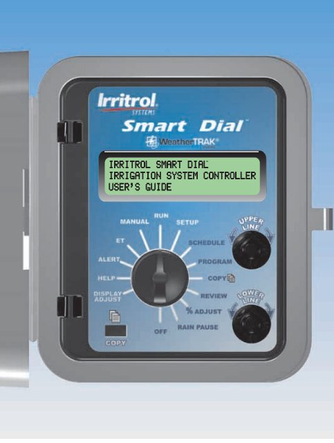
<strong>Smart</strong> Dial Control Module ComponentsUpper LineLower LineInformation DisplayLarge, easy-to-read digital display provides text information forcontroller setup, programming, operation and messaging functions.4Upper Line DialTurn this dial left or right to select the menu items that appear on theupper line of the display.Lower Line DialTurn this dial left or right to change the input data that appears on thelower line of the displayCopy ButtonThe Copy button is pressed to execute the copy feature commands.Function DialTurn this dial left or right to select the various controller functions. A briefdescription of each function follows on page 5. For detailed information,refer to the accompanying page number.
RUN (p. 39)The normal dial position for automatic operation. Current time/date andcontroller activity is displayed.SETUP (p. 6)To select and define specific controller setup parameters.SCHEDULE (p. 16)To select and define the watering day schedule for stations using the FullyAutomated program mode.PROGRAM (p. 15)To enter specific watering program information required for each station.COPY (p. 32)To transfer programming data from one station to another. Also enablesrestoration of the Setup, Schedule and Program default settings.REVIEW (p. 34)To review watering program settings for each station.% ADJUST (p. 36)To adjust the total applied irrigation to a Fully Automated station zone.Adjustment range: 25% increase to 50% decrease in 5% increments.RAIN PAUSE (p. 41)To suspend automatic watering for a period of 1 to 14 days.OFF (p. 42)To terminate and suspend all watering activity.DISPLAY ADJ (p. 50)To adjust the display screen contrast.HELP (p. 44)To display various Help Menu items for troubleshooting assistance.ALERTS (p. 42)To indicate system problems and operational conflictsET (p. 40)To display various ET values and adjust plant coefficient (Kc) factors.MANUAL (p. 39)To manually control station watering operation.5
Setup ProceduresThe information entered in the Setup procedures will adapt the <strong>Smart</strong> Dial foroperation in the local environment. The Setup menu items are accessed inthe following order:Set Irrigation StartMicrozoneSet Water WindowWT VersionSet High ET StartStackingSet ClockSet Water District NumberSet Time ZoneSet Maximum Backup ETAuto Daylight Savings?Rain Service ActiveSet Maximum Active Stations Set Zip CodeSerial NumberSet ET Zone NumberPhase IntegrityGroup NumberLock PhaseRadio AntennaSet Irrigation Cycle Start TimeThe irrigation cycle start time initiates watering for the scheduled day andmarks the beginning of the “Water Window” duration.• Turn the Function dial to SETUP.• Turn the Upper Line dial to select Set Irrig Start (Hour).• Turn the Lower Line dial to adjust the start time hour (a.m. or p.m.).• Turn the Upper Line dial to select Set Irrig Start (Minute).• Turn the Lower Line dial to adjust the start time minute.Note: The beginning of the watering day is 12:01 a.m. and is thereforethe earliest possible irrigation start time.Example: Irrigation start time set to 1:15 a.m.6
Set Water WindowThe Water Window is the duration of time allotted for irrigation on a scheduledwatering day. The minimum Water Window duration is 6 hours and isadjustable up to 23 hours and 59 minutes. The Water Window end time will beautomatically calculated and displayed when the duration is entered.Important: The Water Window duration must enable all scheduledirrigation for the day to be completed. Any scheduled irrigation remainingwhen the Water Window end time occurs will be carried over to the nextscheduled watering day and an “Alert” condition will occur.If the Water Window extends past 12:00 a.m. (midnight) into anunscheduled or restricted watering day, irrigation can occur.• Turn the Upper Line dial to select Set Water Window (Hour).• Turn the Lower Line dial to select hours (6 to 23).• Turn the Upper Line dial to select Set Water Window (Minute).• Turn the Lower Line dial to select minutes (0 to 59).• Example: The Water Window duration is set for 7 hours. With a start timeset for 1:15 a.m., the resulting end time is 8:15 a.m.Set High ET StartIf the daily calculated ET rate is higher than can be replenished in one runcycle of the scheduled stations, the High ET start time will enable thestations which require additional irrigation to run again in the same day.• Turn the Upper Line dial to select Set High ET Start (Hour).• Turn the Lower Line dial to select the start time hour (1 p.m. to 9 p.m.).• Turn the Upper Line dial to select Set High ET Start (Minute).• Turn the Lower Line dial to select start time minutes (0 to 59).Example: High ET start time set for 1:15 p.m.7
Set Clock• Turn the Upper Line dial to select Set Clock (Year) (or the portion of thecurrent time or date to be set).• Turn the Lower Line dial to select the the current value.• Repeat the procedure to set the current Month, Day, Hour and Minute.Example: Date set to February 4th, 2004 and current time is 4:47 p.m.Select Time ZoneThe daily ET Everywhere service broadcast updates the controller clock tocurrent Greenwich Mean Time (GMT). The GMT data must be corrected forthe local time zone to enable synchronization.• Turn the Upper Line dial to select Set Time Zone.• Turn the Lower Line dial to select the applicable time zone option menu.Example: Hawaii time zone selected.8
Select Automatic Daylight SavingsThis option enables the controller clock to be automatically adjusted to theDaylight Savings time change.• Turn the Upper Line dial to select Auto Daylight Savings?• Turn the Lower Line dial to select Yes or No.Example: Automatic Daylight Savings adjustment option is selected.Select Maximum Active StationsImportant: Selecting a higher station count than actual can cause theWater Window duration to be exceeded, resulting in a condition alert.Setting a lower station count than actual will prevent some of thestations from operating.• Turn the Upper Line dial to select Set Max Active Stations.• Turn the Lower Line dial to select the current value.Example: The controller is currently using 11 stations.View Serial Number• Turn the Upper Line dial to select Serial Number. Record the number forfuture reference.Example: The controller serial number is 00000056.9
Phase IntegrityThe Phase Integrity display shows the current signal reception strengthvalues of four receiver phases labeled A, B, C and D. This information willbe used during the ET Everywhere service activation procedure.• Turn the Upper Line dial to select Phase Integrity.Example: A typical Phase Integrity screen.Note: If a value of 32 or above is not indicated, install external antenna kit,P/N 102-5581 to increase reception strength.The pulsing star symbol in the upper display corner indicates normalsignal-acquisition activity.Lock PhaseDuring the ET Everywhere service activation procedure, the signal phasewith the highest integrity value will be used. Once service is established, thecontroller will scan all phases and automatically lock to the strongest signal.• Turn the Upper Line dial to select Lock Phase.• Turn the Lower Line dial to select a phase designator.Example: Receiver locked to Phase B.View Microzone NumberThe Microzone number is automatically downloaded during theET Everywhere service activation procedure and displayed for reference only.• Turn the Upper Line dial to select Microzone (8-digit number).Example: Typical Microzone number screen.10
View WeatherTRAK Firmware Version Number• Turn the Upper Line dial to select WT Version.Example: Current WeatherTRAK firmware version is 00300P61.Select Stacking OptionWhen the Stacking option is enabled, the controller is constrained to runone automatic watering schedule (A or B) at a time. Overlapping stationcycle starts are prioritized as follows: Schedule “A” stations followed byschedule “B” stations; number sequence from low to high.When the Stacking option is not enabled, one station in schedule A andone station in schedule B can operate concurrently.Important: Before selecting the “Stacking No” option, ensure thehydraulic capacity of the irrigation system and the controller’s maximumoutput current will not be exceeded if two stations operate concurrently.• Turn the Upper Line dial to select Stacking.• Turn the Lower Line dial to Yes or No.Example: Stacking option is selected.11
Define the Automatic Watering Day ScheduleThe Fully Automated program mode requires a watering day schedule todetermine which days are eligible for irrigation.Note: If the daily ET calculation determines that watering is not requiredfor a scheduled day, watering will not occur. Automatic watering will neveroccur on an unscheduled or restricted day.Two separate watering day schedules (A and B) can be defined. The stationis then assigned to either schedule A or B.Select the Schedule to Define• Turn the Function dial to SCHEDULE. By default, schedule A is selected.• To select schedule B, turn the Lower Line dial to display Sch B.Example: Schedule A selected.Select the Schedule FormatFor each watering day schedule, one of four formats can be used.“Automated by WeatherTrak” is assigned by default. Using this format makesall days eligible (unless otherwise specified) then selects days based on dailyET requirements.Continue at Automated by WeatherTRAK Schedule below, or select one ofthe following schedule formats and continue at the corresponding page.Odd/Even Day Schedule (page 17).Day Interval Schedule (page 18).Days-of-Week Schedule (page 19).❑ Automated by WeatherTRAK Schedule• Turn the Upper Line dial to select Set Water Days SCH A (or B)Automated by WeatherTRAK as shown in the example below.16(CONTINUED)
A feature of this schedule format enables one day of the week to berestricted from watering. To utilize this feature:• Turn the Upper Line dial to select Best Non-Water Day Sch A (or B).• Turn the Lower Line dial to select a specific day of the week to restrictwatering, or None if no restricted days are required.Example: Sunday selected as a restricted day.(CONTINUE ON PAGE 20)❑ Odd/Even Day ScheduleThis format schedules all odd-or all even-number calendar days.• Turn the Upper Line dial to select Set Water Days SCH A (or B)Automated by WeatherTRAK.• Turn the Lower Line dial to select Odd/Even.Example: Odd/Even watering day schedule selected.• Turn the Upper Line dial to select Water Day Odd/Even Sch (Odd).• To select Even, turn the Lower Line knob to display Even.Example: An Even watering day format is selected for Schedule A.Note: When using the Odd number day schedule, two consecutivewatering days will occur at the end of months with 31 days.(CONTINUE ON PAGE 20)17
❑ Interval Day ScheduleThe Interval format provides a periodic watering day schedule rangingfrom 01 (every day) to 31 (every-31st day) in one-day increments.For example, a 02 interval schedules a watering day followed by one dayoff, or watering every other day. A 06 interval schedules a watering dayfollowed by five days off, and so on up to 31.• Turn the Upper Line dial to select Set Water Days SCH A (or B)Automated by WeatherTRAK.• Turn the Lower Line dial to select Interval.Example: Interval watering day schedule selected for Schedule A.• Turn the Upper Line dial to select the desired Interval number (01–31).Example: A two-day (02) interval is selected for Schedule A.Note: When the function dial is turned to the REVIEW position, thenumber of days remaining until the next scheduled watering day in theinterval schedule will be displayed.Example: A two-day interval is selected and the next scheduled wateringday is today.(CONTINUE ON PAGE 20)18
❑ Days-of-Week ScheduleThis watering day format enables each day of the week (per month) to beincluded or excluded from the schedule.• Turn the Upper Line dial to select Set Water Days SCH A (or B)Automated by WeatherTRAK (default).• Turn the Lower Line dial to select Set Water Days Sch A (or B)Days of Week.Example: Watering by days of the week format selected for Schedule A.• Turn the Upper Line dial to display the days of the week by month.The cursor will underline the letter Y (Yes) below the letter S (Sunday).Note: By default, all days of all months are selected as active (Y).Example: January is selected and watering can occur every day.• To remove specific days of the week from the watering schedule, turn theUpper Line dial to position the cursor under the day abbreviation. Turnthe Lower Line dial once to replace the letter Y with a dash (inactive).Example: In January, watering is set for Monday, Wednesday and Friday.Note: Moving the cursor past the last day of the week will advance thedisplay to the next month.• Repeat this procedure for each month.(CONTINUE ON PAGE 20)19
Note: If you have not completed the System Profile Worksheet, take timeto do so before proceeding. Having the necessary information on hand tocomplete the following procedures will be very helpful.To establish an accurate ET profile, the following parameters must beentered for each active station:✔ Sprinkler type ✔ Soil type ✔ Plant type✔ Root depth ✔ Microclimate ✔ Precipitation rate✔ Efficiency factor ✔ Slope % ✔ Location on slope• Turn the Upper Line dial to select Set Program Mode Sta (01)Fully Automated (default). See example below.Select Water Day Schedule A or B• Turn the Upper Line dial to select Set Schedule Sta (01) Sch A (default).• To select Schedule B, turn the Lower Line dial to display Sch B.Example: Schedule A is selected.Select Water Window UsageSelecting “Yes” will constrain station operation to occur within the setWater Window time period. Selecting “No” enables the station to operateat any time during a scheduled watering day.• Turn the Upper Line dial to select Use Water Window Sta (01)Yes (end time [computed]) (default).• To select No, turn the Lower Line dial.Example: Water Window use option elected.20
Select Sprinkler Type• Turn the Upper Line dial to select Set Sprinkler Type Sta 01Spray Head (default).• Turn the Lower Line dial to select the sprinkler type from the followingmenu:Spray Head (fixed) Mixed ImpactsFull-circle Rotor Steam RotorsPart-circle Rotor BubblerMixed Rotors Drip EmitterFull-circle Impact Stream SprayPart-circle ImpactExample: Mixed Rotors selected for station 01.Set Precipitation RateNote: The Precipitation Rate (PR) default value for each sprinkler type canbe used to establish a baseline watering program routine. To determinesite-specific sprinkler PR values, refer to Appendix A: Acquiring SprinklerPrecipitation Rate on page 51.The sprinkler PR value can be set from 0.10 to 9.99 inches per hour.• Turn the Upper Line dial to select Precip Digit 1 Sta (01).• Turn the Lower Line dial to adjust the first digit.• Turn the Upper Line dial to select digit 2.• Repeat this procedure to adjust the second and third digits.Example: The PR entered is 0.75 inches per hour (default).21
Set Sprinkler Efficiency RateNote: The published Efficiency Rate for the selected sprinkler type isdisplayed as the default value. Using the default value is recommended ifthe actual Efficiency Rate is not known at this time. The defaultEfficiency Rate can be adjusted to fine-tune the watering program asfollows:To decrease watering, increase the Efficiency Rate. Conversely, toincrease watering, decrease the Efficiency Rate.The Efficiency Rate value is adjustable from 10–99%.• Turn the Upper Line dial to select Effic’ncy Digit 1 Sta (01) 75Percent.• Turn the Lower Line dial to adjust the first digit.• Turn the Upper Line dial to select the second digit with the cursor.• Turn the Lower Line dial to adjust the second digit.Example: The default efficiency rate value for the sprinklers controlled bystation 01 is 75%.Select Soil Type• Turn the Upper Line dial to select Select Soil Type Sta (01).• Turn the Lower Line dial to make a selection from the following menu:SandyClay LoamSandy LoamClayLoamExample: The soil type selected for station 01 is Clay Loam.22
Select Plant TypeNote: For hybrid turf or plant applications, select the Custom Plant A, Bor Turf option.• Turn the Upper Line dial to select Select Plant Type Sta (01).• Turn the Lower Line dial to make a selection from the following menu:Warm Season GrassMixed - Medium Water UseCombined GrassMixed - Low Water UseFlowersNative Trees/ShrubsTreesNative GrassesShrubs - High Water Use Custom Plant AShrubs - Medium Water Use Custom Plant BShrubs - Low Water Use Custom TurfMixed - High Water UseExample: The plant type selected for station 01 is “Warm Season Grass.”Select Root DepthNote: The <strong>Smart</strong> Dial uses a soil moisture depletion model to determinethe irrigation requirements for each watering zone. A longer root depthvalue increases the number of days between watering. Conversely, ashorter root depth value decreases the number of days betweenwatering. Select a root depth value from 2 to 36 inches.• Turn the Upper Line dial to select Select Root Depth Sta (01).• Turn the Lower Line dial to select root depth from 2–36 inches.Example: The root depth entered for station 01 is 6 inches.23
Select MicroclimateSelect the microclimate that best describes the major portion of thewatering zone.• Turn the Upper Line dial to select Set Microclimate Sta 01.• Turn the Lower Line dial to make a selection from the following menu:Sunny All DaySunny Most of the DayShady Most of the DayShady All DayExample: The microclimate selected for station 01 is“Sunny Most of the Day.”Select Slope % FactorSelect the slope factor or gradient that best describes the major portionof the watering zone.• Turn the Upper Line dial to select Set Slope Factor Sta 01.• Turn the Lower Line dial to select a slope factor from the followingmenu:Gentle: 6–8% (16.6:1–12.5:1) Grade (6%)Mild: 9–12% (11.1–8.3:1) Grade (9%)Moderate: 13–20% (7.7:1–5:1) Grade (13%)Steep: > 20%+ (> 5:1) Grade (20%)Example: The slope factor selected for station 01 is “Gentle 6–8% Grade.”24
Select Sprinkler Location on SlopeSelect the location on the slope that best describes sprinkler placement.• Turn the Upper Line dial to select Sprinkler Location Sta (01).• Turn the Lower Line dial make a from the following menu:All Parts of SlopeTop of SlopeMiddle of SlopeBottom of SlopeExample: The slope factor selected for station 01 is “All Parts of Slope.”Set Usable Rainfall % Factor (optional)Setting a rainfall effectivity % factor is available when the Rain Serviceoption is enabled. The usable rainfall % value is the percentage ofrainfall expected to reach the plant root zone. Enter a value from0 to 100%. If the service is not activated, “Inactive” will be displayed.• Turn the Upper Line dial to select Usable Rainfall Sta (01).• Turn the Lower Line dial to select a percentage value from 0–100%(in 25% increments).Example: Usable Rainfall feature is inactive.25
Completing the Program• Turn the Upper Line dial to select Program Complete Sta (01).• Repeat the programming procedure as required for each station,starting on page 15.Important: If other stations have the same or similar watering routineattributes, the Copy feature enables all program attributes of onestation to be easily transferred to any or all other active stations andedited as necessary; greatly simplifying the programming procedure.See “Copy” on page 32 for detailed information.❑ User Programmed–ET Service Active ModeIn this program mode, you will establish a baseline or target wateringroutine for the station by defining four specific operating parameters. Theroutine is then automatically updated and modified as necessary each dayusing ET data received from the ET Everywhere service broadcast.• Turn the Upper Line dial to select set Program Mode Sta (01)Fully Automated (default).• Turn the Lower Line dial to select Set Program Mode STA (01)User Programmed – – with ET. See example below.The operating parameters are listed in the following menu order:Set Cycle TimeSet Number of CyclesSet Soak TimeSet Watering Day Schedule26
Set Cycle TimeCycle Time is the duration of time a station operates during a wateringcycle. Enter a value from 0.1 to 99.9 minutes.• Turn the Upper Line dial to select Set Cycle Time Sta (01)05.0 Minutes (default).• Turn the Lower Line dial to select the minutes value (0–99).• Turn the Upper Line dial to select Set Cycle 10ths.• Turn the Lower Line dial to select the 10ths of a minute value (1–9).Example: Cycle Time is set for 12.5 minutes.Select Number of CyclesThis program element sets the number of times the station will run on ascheduled watering day. Select 1 to 20 cycles.• Turn the Upper Line dial to select Set # Of Cycles Sta (01)01 Cycles/Operating Day (default).• Turn the Lower Line dial to select the value (1–20).Example: Two watering cycles per scheduled operating day have beenselected for station 01.27
Set Soak TimeSoak Time is a delay period that occurs between station watering cycles.The delay enables the water from a one run cycle to soak into the rootzone before the next cycle begins. The Soak Time value is adjustablefrom 10 to 480 minutes (8 hours) in 10-minute increments.• Turn the Upper Line dial to select Set Soak Time Sta (01)30 Minutes (default).• Turn the Lower Line dial to select the minutes value (10–480).Example: Soak time for station 01 is set for 50 minutes.Set Watering Day ScheduleThe watering day schedule determines which days of the year will beeligible for watering. “Let Me Set Water Days” is the default format thatenables each day of the year to be scheduled as eligible or ineligible forwatering operation.To use an alternate scheduling method, continue at a procedure headingand corresponding page number as follows:Water 7 Days Per Week – Every day eligible for operation (page 29).Set Water Day Interval – Eligible water day routine set according to howoften watering can occur (page 30).❑ Let Me Set Water Days• Turn the Upper Line dial to select Set Water Days Sta 01Let Me Set Water Days (default).Example: Let Me Set Water Days format selected.(CONTINUED)28
• Turn the Upper Line dial to display the days of the week by month.The cursor will underline the letter Y (Yes) below the letter S (Sunday).Note: By default, all days of all months are selected as active (indicatedby the letter Y).Example: Jan (January) is selected and watering can occur every day.• To remove specific days of the week from the watering schedule, turn theUpper Line dial to position the cursor under the day abbreviation. Turn theLower Line dial once to replace the letter Y with a dash (inactive).Example: In January, every Sunday and Saturday are excluded fromwatering.Note: Moving the cursor past the last day of the week will advance thedisplay to the next month.• Repeat this procedure for each month.• Proceed to “Completing the Program” on page 31.❑ Water 7 Days Per Week• Turn the Upper Line dial to select Set Water Days Sta (01)Let Me Set Water Days (default).• Turn the Lower Line dial to select Set Water Days Sta (01)Water 7 Days Per Week as shown below.• Proceed to “Completing the Program” on page 31.29
❑ Set Water Day IntervalThe Interval format enables a you to select a periodic water day scheduleranging from 01 (every day) to 31 (every 31st day) in one-day increments.For example, a 02 interval schedules one watering day followed by oneday off, or watering every other day. A 06 interval schedules one wateringday followed by five days off, and so on up to 31.Note: The first day of an Interval schedule is today. Watering can occurtoday if the irrigation start time and water window end time have not yetoccurred. When the function dial is in the RUN position, the number ofdays remaining before the next scheduled watering day will bedisplayed.• Turn the Upper Line dial to select Set Water Days Sta (01)Let Me Set Water Days (default).• Turn the Lower Line dial to select Set Water Days Sta (01)Set Water Day Interval as shown below.• Turn the Upper Line dial to select Set Water Days Sta (01)01 Day (water every day) (default).• Turn the Lower Line dial to change the Interval number (01–31).Example: A 2-day or every-other-day Interval is set for Station 01.30
Completing the Program• Turn the Upper Line dial to select Program Complete Sta (01).• Repeat the programming procedure as required for each station,starting on page 15.Important: If other stations have the same or similar watering routineattributes, the Copy feature enables all program attributes of onestation to be easily transferred to any or all other active stations andedited as necessary; greatly simplifying the programming procedure.See “Copy” on page 32 for detailed information.❑ User Programmed–ET Service Inactive ModeImportant: The program values entered for this program mode are thesame as the “User Program-ET Service Active” mode. However, allprogramming values entered will remain constant.• Turn the Upper Line dial to select Set Program Mode Sta (01)Fully Automated (default).• Turn the Lower Line dial to select Set Program Mode Sta (01)User Programmed – – NO ET. See example below.• Refer to “User Programmed – ET Service Active Mode” on page 26.Begin the programming procedure on page 27 at “Set Cycle Time.”31
❑ Station Program Off ModeThe Station Program Off mode enables any station to be made inactivewithout altering or changing any of its attributes.• Turn the Upper Line dial to select Set Program Mode Sta (01).“Fully Automated” mode will be selected by default.• Turn the Lower Line dial to select Set Program Mode Sta (01)) OFF.• Repeat this procedure to turn off additional stations as needed.Note: To return a station to active status, simply assign any operationalprogram mode.Control FeaturesCopyThe Copy feature enables you to transfer station program values quicklyfrom one station to another or to all active stations simultaneously.Copy from Station to Station(s)• Turn the Function Dial to COPY.Example: The display will show Copy from Sta 01 to Sta 01 (Press Copy).• Turn the Upper Line Dial to select the station number to copy from.• Turn the Lower Line Dial to select the station number or “All Stations”(listed after the highest active station number) to copy to.Example: Station 01 data will be copied to all stations.(CONTINUED)32
• Press and hold the COPY button until Copying Done! is displayed.Restore <strong>Controller</strong> Default ValuesThe Copy feature also enables the controller default values for Program,Setup and Schedule to be easily restored when replacement of the currentuser-input values is desired.The Program defaults can be restored to individual stations or to all activestations simultaneously.Restore Program Defaults• Turn the Function Dial to COPY. The display will showCopy From STA 01 To STA (01) as shown in the example below.• Turn the Upper Line Dial to select Copy Program Defaults.• Turn the Lower Line Dial to select an individual station number or allactive stations to restore the default value.Example: Program default values will be restored to all active stations.• Press and hold the COPY button until the Copying Done! is displayed.33
Restore Schedule or Setup DefaultsNote: The Schedule and Setup default values are restored to all activestations simultaneously.• Turn the Function Dial to COPY. The display will showCopy From Sta (01) To Sta (01) as shown below.• Turn the Upper Line Dial to select Copy Schedule Defaults orCopy Setup Defaults.Example: The Schedule default values are selected.• Press and hold the COPY button until the Copying Done! is displayed.Review FeatureThe Review feature provides a convenient, at-a-glance overview of thecurrent watering day schedule and program values for each station.The review information is displayed in an abbreviated format that enablesall pertinent station information to be viewed on a single screen.• Turn the Function Dial to REVIEW. The review screen for station 01 willbe displayed.•Turn the Upper Line Line to select the station number to be reviewed.(CONTINUED)34
Example: The illustration below depicts a typical review screen.The format will vary slightly by displaying information that pertainsspecifically to the station being reviewed.StationNumberCycle TimeDurationWateringCyclesper DayProgramModeScheduledWatering Days% AdjustFactorSoak TimeDurationIn the example above, Station 01 cycle time is 25.6 minutes, one timeper day and is assigned to the “Fully Automated” program mode. If theassigned program mode is “User Programmed-With ET Service Active”“U–ET” will be displayed. “U–NO” will be displayed if the “UserProgrammed –With ET Service Inactive” program mode is used.The scheduled watering days for week 2 of an 8-week schedule areSunday and Thursday. The station run time has a 0% adjustment factorand a 5 minute soak time.If an Interval watering day schedule is assigned, the Interval number(01–31) and the number of days remaining until the next active wateringday will be displayed.Example: The review screen below indicates Station 01 is assigned tothe “User Programmed with ET Service Active” (U–ET) program mode.Watering days are scheduled on a 3-day (03) Interval with two daysremaining until the next eligible watering day.35
% Adjust FeatureThe % Adjust feature provides a convenient method of fine-tuning stationwatering zones that are slightly dryer or wetter than optimum. The sumwatering of any Fully Automated station can be increased 5 to 25% ordecreased 5 to 50% in 5% increments. All factors that determine how muchirrigation time the station receives are instantly recalculated and adjusted.Note: This feature applies only to stations using the “Fully Automated”program mode. “Non-Adjustable Mode” will be displayed for any station(s)using a ”User Programmed” mode.Note: Using the Review feature in conjunction with % Adjust provides aconvenient reference of actual station operating values before and afterthe calculated adjustments.• Turn the Function Dial to REVIEW. The display will show all currentoperating control values for station 01.• Turn the Upper Line dial to change the station number as needed.Note: The Review screen shows only future days scheduled to water.Therefore, reviewing Week 2 is recommended to ensure all scheduledwatering days of the week are displayed.• Turn the Lower Line dial to select Week 2 watering day schedule.Example: Station 01 is currently set to run for 25.6 minutes, one time perday on Tuesday and Friday of Week 2. It has no % adjustment factorand a soak-in time of 5 minutes.(CONTINUED)36
• Turn the Function dial to ADJUST.• Turn the Upper Line dial to select the station to adjust. In this examplestation 01 is selected.• Turn the lower dial to the right to increase the percentage (+25 maximum)or left to decrease the percentage (-50% minimum).Example: The Cycle Time for station 01 has been increased by 20%.• Turn the Function dial to REVIEW to display the results of the adjustment.Example: Note the changes from the original settings shown in exampleScreen 1 below, to the adjusted settings in example Screen 2. Station 01is now set to run 20.5 minutes, one time per day, Monday, Wednesdayand Thursday. The net result of the 20% increase is actually a reductionin cycle time with an increase in watering days. The <strong>Smart</strong> Dial calculateda watering routine solution that would increase irrigation withoutexceeding the soil moisture depletion rate, possibly resulting in run off.Example Screen 1Example Screen 237
ET FeatureThe screens provided within in the ET feature enable the current ET valuesfor daily and weekly watering operations to be reviewed and Kc values forCustom Turf and Plants to be entered and adjusted.Review Current ET Values• Turn the Function dial to ET.• Turn the Upper Line dial to select from the following screen menu options:Current Daily ET Current Weekly ETExample: The Current Weekly ET value is 3.00. The last broadcast ET datawas received was on March 9th, 2004 at 3:41 p.m.Note: To adjust the Weekly ET value, see “Troubleshooting” on page 55.Adjust Custom Turf and Plant Kc ValuesWhen Custom Turf or Plants are entered as the station “Plant Type,”a Kc (crop [turf] coefficient) default value of 1.00 is used to calculate ET.Note: Custom Plant values use the same factor for all months. CustomTurf values are set specifically for each month.To adjust the current Kc value, use the following procedure:• Turn the Function dial to the ET position.• Turn the Upper Line dial to select a menu option:Set Kc Custom Plant ASet Kc Custom Plant BSet Kc Custom Turf (set each month)• Turn the Lower Line dial to adjust the value from 0.10 to 1.20.Example: The Custom Turf Kc value for January is adjusted to 0.10.• Repeat the above two steps to set a Kc value for each month.38
Operating Modes and FeaturesRun ModeRUN is the Function dial home position. The display indicates the currentdate and time and any current Automatic and/or Manual station wateringoperation.Example: The current date is February 4th, 2004. The current time is10:23 p.m. Station 03 is currently running a schedule A watering routine.Manual ModeManual mode enables a single station or sequence of stations to beoperated at any time needed. Manual operation can occur simultaneouslywith Automatic operation and is not affected by the Rain Pause mode oran active Rain Sensor.Important: Ensure the hydraulic capacity of the irrigation system andthe controller’s maximum output current will not be exceeded withconcurrent Automatic and Manual operation.Specific Station Operation• Turn the Function dial to MANUAL.• Turn the Upper Line dial to select the applicable station number.• Turn the Lower Line dial to select a temporary cycle time from 1 to 99minutes. The selected station will start immediately.• Repeat the procedure to queue additional stations. Stations will run innumeric sequence; as one station finishes, the next station starts.Example: Station 01 is running and has 2.6 minutes of time remaining.Note: Cycle time can be adjusted by turning the Lower Line dial whilethe station is operating. Selecting 00 minutes turns off operation.(CONTINUED)39
Note: To discontinue manual operation, turn the Function dial to OFF,pause to display “Irrigation is Turned OFF,” then return the dial to RUN.Note: To review current operating status, turn the Function dial to RUN.Example: Station 03 is currently running in Automatic watering schedule“A” and station 01 is running in Manual mode.Sequential Station OperationAll active stations can be set to operate in numeric sequence, one station ata time. As one station finishes operation, the next station in sequence starts.• Turn the Function dial to MANUAL.• Turn the Lower Line dial to select All Stations.• Turn the Upper Line dial to select 00.0 Minutes.• Turn the Lower Line dial to select a cycle time from 1 to 99 minutes.The temporary cycle time selected will be applied to all active stations.Example: Station 01 is running and has 5.7 minutes of time remaining.Note: Cycle time can be adjusted with the Lower Line dial while thestation is operating. Selecting 00 minutes turns off operation.Note: To discontinue manual operation, turn the Function dial to OFF,pause to display “Irrigation is Turned OFF,” then return the dial to RUN.Note: To review current operating status, turn the Function dial to RUN.Example: Station 03 is currently running in Automatic watering schedule“A” and station 01 is running in Manual mode.40
Rain Pause ModeThe Rain Pause mode enables all automatic watering activity to be placedon hold for a duration of 1–14 days. When initiated, all automatic wateringoperations will be turned off and remain off until the selected duration haselapsed or “00 Days Remaining” is selected.Note: All remaining controller functions, including Manual operations, areavailable while the controller is in the Rain Pause mode.• Turn the Function dial to the RAIN PAUSE position.• Turn the Lower Line dial to select a duration from 1–14 days.Example: A two-day pause has been selected.The Rain Pause mode is also displayed while the Function dial is in theRUN position.Example: The function dial is in the RUN position, Rain Pause is activeand Manual mode is not currently active.If a Manual watering operation is active, the display will indicate thestation number currently running.Example: The function dial is in the RUN position, Rain Pause is activeand station 02 is currently running in Manual mode.41
Off Mode - <strong>Controller</strong> ShutdownWhen the Function dial is turned to the OFF position, all watering activitywill be terminated and remain off until the dial is turned to another position.Leave the Function dial in the OFF while the irrigation system is winterizedor for any prolonged period of time greater than the 14-day maximumRain Pause delay.Note: All non-watering controller functions remain unaffected by the Offmode, including daily ET Everywhere service broadcast downloads.• Turn the Function dial to the OFF position.Example: Irrigation is turned off.• Turn the Function d ial to any other position to exit the OFF mode.System AlertsThe System Alert screens provide the current status of all key controlleroperations. If the controller detects a problem in the watering program/scheduling, signal reception or the 24V field output, the alert message“Status: Warning See Alert” will be displayed. The alert message willcontinue to be displayed until the problem has been corrected.Use the following procedure to determine the cause of the problem:• Turn the Function dial to ALERTS.• Turn the Upper Line dial to access status information from the followingmenu:Alert StatusDay Status Schedule BWater Window Status Communication StatusDay Status Schedule A Electrical StatusExample: Alert Status menu item selected — no alerts at this time.42
Water Window StatusThis alert condition occurs when the cumulative station cycle and soaktime exceeds the current Water Window duration.• To resolve the problem, increase the Water Window duration, and/or reducethe station cycle times or add eligible days to the watering schedule.Day StatusThis alert condition occurs when there are not enough eligible wateringdays available to complete the required operation.• Example: Alert Status screen selected.and a Day conflict has occurred.• Turn the Upper Line dial to select Day Status Schedule A (or B)Alarm on Station to determine the affected schedule.• To resolve the problem, turn the Function dial to SCHEDULE. Select theindicated Schedule and increase the number if eligible watering days.Communication StatusThis alert will appear if the <strong>Smart</strong> Dial fails to receive the daily ETEverywhere Service broadcast data for four consecutive days. The alert willcontinue to be shown until communication is restored or the Function dial isturned to the Off position.Electrical StatusThis alert indicates that an over-current condition exists on one or morefield outputs. The <strong>Smart</strong> Dial will attempt to operate all active stations asprogrammed, but will automatically bypass the station and advance to thenext programmed station in sequence.To resolve the problem, check the field wiring for damaged or loose wiresplices at the valve solenoid connection and repair as necessary. A faultyvalve solenoid can also cause this condition and should be tested with adigital ohmmeter for the manufacturer’s specified normal resistance range.43
System HelpIf the controller problem can not be resolved using the troubleshootingsteps provided in Appendix B, please contact the <strong>Irritrol</strong> Customer ServiceHelp Line at 1-800-634-8873, Monday thru Friday, 7:30 a.m. to 4:00 p.m.(pacific time).During the service call, you may be asked to review and adjust variouscontroller settings to help diagnose the issue.• Turn the Function dial to HELP. The customer service phone number willbe displayed.• Turn the Upper Line dial to access specific information from the followingmenu:Current Weekly ETBeep on Message? (Yes/No)*Serial NumberPhase IntegrityMicrozoneLock Phase (A, B, C, D and None)*Data Encryption Mask Reset/Erase or Restart **Start Times (First Irrigation and High ET Start)*Note: The current settings for “Beep on Message” and “Lock Phase”can be changed. The remaining Help menu items are for reference,review or service use only.Example: Beep on Message?– Changed from Yes, (default) to No.** Important:The “Reset/Erase or Restart” menu item is for serviceuse only. Do not use this procedure unless instructed to do so by acustomer service representative.44
Installation ProceduresInstalling the <strong>Controller</strong>For safe, reliable operation, select an installation site for the controller thatwill provide the following conditions:Indoor Models:• An enclosed or sheltered area, protected from all weather elements anddirect sunlight.• Access to a grounded, 120 Vac wall receptacle on a branch circuit thatis not controlled by a light switch or utilized by a major appliance.• Access to the control valve wiring.Outdoor Models:• Protected from direct exposure to irrigation spray, afternoon sun, windand snow.• Access to a grounded 120 Vac branch circuit that is not controlled by alight switch or utilized by a major appliance.• Access to the sprinkler control valve wiring.1. Open the controller door. On the outdoor model, press the control modulelatch to the right. Swing the hinged control module outward fromright to left.Note: On the outdoor cabinet, the lower mounting pilot holes areflashed over. If screw anchors are to be installed, remove the flash fromone or both pilot holes as needed using a 1/4" drill bit.Note: Screw anchors must be used when the controller is installed ondrywall or masonry. Temporarily position the controller on the wall, markthe mounting hole locations and install the screw anchors.2. Install the top mounting screw leaving approximately 1/4" of the screwshaft exposed.3. Align the keyhole on the cabinet back panel with the screw head. Slidethe controller downward to capture the screw shaft in the keyhole slot.Note: Adjusting the screw depth may be required to enable the controllerto fully engage the mounting screw.4. Install the lower mounting screw(s) to secure the controller cabinet.Note: The field wiring access hole in the base of the Outdoor controllercabinet accepts a 1-1/4" conduit and the Indoor cabinet accepts 3/4"conduit. Install conduit at this time if required by local electrical codes.45
Connecting the Control ValvesNote: Using 18-gauge, multi-strand, direct-burial irrigation valve connectioncable is recommended. Select a cable that provides at least one wire for eachvalve and one extra wire for the valve common connection.CAUTION: To prevent corrosion and possible short circuit, usewaterproof wire connectors on all wire splices.1. To provide the valve common connection, splice one cable wire(generally the white wire) to one solenoid lead from each valve.2. Connect a separate wire to the remaining solenoid lead of each valve.For reference, note the wire color code used for each valve connectionand it’s associatedwatering zone.3. If a master valve or pumpstart relay is used, makethis connection in thesame manner.CAUTION: The pumpstart relay must be rated24 Vac at 0.375A max.Never connect directlyto the pump starter.4. Route the wire cable intothe controller through thelarge opening in the baseof the housing or throughconduit if installed.5. Leave about 8" of cableremaining in the cabinet.Remove the outer jacketto expose about 6" ofwire. Strip insulation backon each wire about 3/8".6 Secure the valve commonwire to terminal “VC” andeach valve wire to theapplicable station numberterminal. See Figure 1.46Figure 1Master Valve/PumpRelay Connection0.375 A (max.)Pump Start Relayor Master ValveMVValve CommonConnection (VC)12ControlValves3Valve Common Wire
Connecting a Rain Sensor (optional)Important: The sensor circuit is designed for a Normally Closed rainsensor. If a rain sensor is NOT connected, the Sensor switch must be inthe “Bypass” position or the jumper wire must be installed across thesensor terminals.If the jumper wire is removed and the Sensor switch is in the “Active”position, the controller will not run automatically.RS 1000 TMTMFigure 2Sensor SwitchWireless Rain Sensor<strong>Irritrol</strong>Wireless RainSensorJumperRemoved1. Insert in the sensor connection cable through the access hole in thebottom of the cabinet.2. Remove the jumper wire from the “Sensor” terminals. Refer to theinstallation instructions included with the Rain Sensor and connectwires accordingly. See Figure 2.3. Place the Sensor switch to the “Active” position.Note: Operation of the rain sensor does not affect reception of theET Everywhere service or Manual controller operations.When the sensor circuit is activated, the controller will continue tooperate for 10 minutes before the Sensor circuit disables Automaticoperation. Automatic operation will resume when the sensor input isterminated.47
Connecting the Indoor Model Power Source and Earth Ground forIndoor and Outdoor Models1. Route the plug-in transformer cable through the small hole provided inthe cabinet bottom and connect to the terminals labeled “24 VAC.”Figure 3Earth Ground TerminalTop of Ground Rod12" Below GradePlug-inTransformer10-Gauge SolidCopper Wire8' Copper CladGround RodCAUTION: The controller’s surge protection circuitry must havean earth ground path to function properly. Proper grounding isespecially important in lightning-prone areas.2. Install an 8' copper-clad ground rod into well-moistened soil to about12" below grade. Connect a 10-gauge solid copper ground wire androute to the controller in the most direct path, avoiding bends smallerthan a 12" radius.Note: Using a small round valve box to cover ground rod is recommended.3. Route the ground wire through the bottom of the cabinet and connectto the “EARTH GND” terminal.4. Close the control module and plug the transformer into a wall outlet.Note: To adjust the controller display contrast, see “Display ContrastAdjust Feature” on page 50.48
Connecting the Outdoor Model Power Source1. For input power wire connections, install a 1/2" NPT threaded conduitbody to the transformer assembly nipple. From the conduit body, installelectrical conduit to the 120 Vac power source.2. Confirm that power has been disconnected at the source by using a voltmeter or voltage detector.3. Route solid copper 14-AWG power, neutral and equipment ground wiresthrough conduit from the power source into the conduit body.4. Using the supplied wire nuts, connect the power wire to Black, neutralwire to White and equipment Ground to Green controller wire.See Figure 4.5. Close and secure the conduit cover.6. Referring to the groundingprocedures on page 48, installand connect an earth ground wire.7. Apply power to the controller.Note: To adjust the controllerdisplay contrast, see “ContrastAdjust Feature” on page 50.Figure 4Neutral/WhiteHot/BlackEquipmentGround/Green49
Installing an External Antenna (optional)If the controller’s built-in antenna does not provide adequate signal reception,an externally-mounted antenna, P/N 102-5581 can be easily installed.1. Remove the access cover from the topinside edge of the control module as shownin Figure 5.2. Route the antenna cable into the controllerthrough the access hole provided in thecabinet base. Do not drill any additionalholes in the cabinet!3. Install the antenna cable connector to thethreaded receptacle.4. Position the antenna at the highest pointabove the controller that will not strain thecable connection. Align the antenna asshown in Figure 5.5. Use the adhesive backing on the antennawhen installaing on a smooth surface.Use the provided fasteners for installation on textured surfaces.6. Change the antenna option setting from Internal to External as describedon page 14.7. Test signal reception strength as described in “View Phase IntegrityData” on page 10. A value of 32 or higher is required.Display Contrast Adjust FeatureFigure 5RequiredAntennaAlignmentThe display screen contrast level can be adjusted for optimum viewing invarious ambient light conditions.• Turn the Function dial to the DISPLAY ADJ position.• Turn the Upper Line dial (Knob 2) left to decrease or right to increase thecontrast level.Example: The Adjust Contrast display screen.50
Appendix A: Acquiring Sprinkler Precipitation RateThe <strong>Smart</strong> Dial controller’s default sprinkler precipitation rate (PR) valuesare based on a composite of the major sprinkler manufacturers’ publishedperformance data. If you do not have the specific sprinkler manufacturer’sperformance data charts, using the default PR values during initial set upwill generally provide an acceptable baseline watering routine. Once thesystem has been up and running for several days, adjustments should bemade to optimize the watering routine of each station.Determining Site-specific PR ValuesThe following procedures will enable you to gather enough site informationto determine a basic PR value for each station. PR value fine-tuning maybe necessary if the system was not installed within the manufacturer’sguidelines.Step A. Do the sprinklers provide head-to-head spray coverage?Yes - Go to Step B.No - Go to Step C.Step B. Do you have the sprinkler manufacturer’s performance data chart?Yes - Go to Procedure 1 below.No - Go to Step C.Step C. Do the sprinklers produce a fogging or misting spray?Yes - Go to Procedure 3 on page 52.No - Go to Step D.Step D. Is the irrigation system less than 10 years old?Yes - Go to Procedure 2 on page 52.No - Go to Procedure 3 on page 52.Procedure 1: Using the Manufacturer’s Performance Data Charts• Record the sprinkler performance data to include nozzle size, operatingpressure and spacing.• If the pressure at the sprinkler appears too high or too low, measure thenozzle spray pressure at the sprinkler nearest to the control valve andfarthest from the control valve. Calculate and record the average pressure.Note: Use a 0–100 psi water pressure gauge with a pitot tube attachmentto measure nozzle discharge pressure.• Find and record the published PR value at the average measured pressure.Note: If the measured pressure is not within the recommended operatingrange, irrigation system rework may be required before a precisePR value can be determined.51
Procedure 2: Using a Basic PR Calculation• Measure and record the row spacing and sprinkler spacing (in feet).• Measure the spray pressure at the sprinkler nearest to the control valveand farthest from the control valve (in psi). Calculate and record theaverage pressure.• Note: Use a 0–100 psi water pressure gauge with a pitot tube attachmentto measure nozzle spray pressure.• Locate and record the sprinkler manufacturer’s published flow rate(in GPM) for a “Full Head” for the sprinkler type, nozzle size and pressure.Note: If the measured pressure is not within the range limit, a rework ofthe system may be required before continuing with this procedure.• Calculate the PR value using the following formula:PR = (96.3 x GPM)/(row spacing x sprinkler spacing).Note: This process assumes the sprinklers are installed in a matchedprecipitation rate arrangement. If this condition does not exist, a reworkof the irrigation system may be necessary.Procedure 3: Using a “Catch Container” AuditNote: This procedure requires a straight-sided container, like a small coffeecan for example, to collect a sample of irrigation water.• Measure the inside diameter of the catch can and multiply by 3.14 todetermine the catch Container Area (CA) in square inches.• Place the container in the watering zone.• Manually Test Run (TR) the station for 10 minutes. Measure and recordthe Collected Volume (CV) of water (in milliliters).• Repeat this procedure several times to obtain an accurate AverageCollected Volume (ACV).• Calculate the PR value using the following formula:PR = (ACV x 3.66)/(TR x CA).Where:ACV = the Average Collected Volume average in millilitersTR = the Test Run time in minutesCA = the catch Container Area in square inchesExample:PR = (35 ml x 3.66)/(10 minutes x 16.5 sq. inches) = 128.1/165 = 0.78 in/hr.52
Appendix B: TroubleshootingResolving Alert Messages—————————————————————✧ Communication AlertPossible Cause: Reception interruption or loss of ET service broadcast.Remedy:• Call HydroPoint Data Systems Customer Service at: 800-362-8774.✧ Day Interval AlertPossible Cause: During times of high ET, the number of days scheduledfor irrigation may not be enough to adequately irrigate all zones.Remedy:• Increase the number of scheduled irrigation days.✧ Electrical AlertPossible Cause: Shorted solenoid or valve wiring.Remedy:• Check for faulty wiring connections and valve solenoids. Repair and/orreplace as necessary.✧ Water Window AlertPossible Cause: During times of high ET, the water window you selectedmay not have enough duration to adequately irrigate all zones.Remedy:• Increase the water window duration.• Increase the number of scheduled irrigation days.• Use % Adjust to decrease watering.Resolving <strong>Controller</strong> Operation Problems —————————————Problem: <strong>Controller</strong> programs correctly but stations are not irrigating.Remedy:• Check the time and date settings and adjust to current time and dateas necessary.• If “Rain Switch” is displayed, the sensor circuit is active and blockingirrigation. If a rain sensor is not installed, confirm the sensor terminalsare connected by a jumper wire and/or the Sensor switch is in the“Bypass” position.• Rain Pause may be active. Turn Function dial to Rain Pause positionand turn the Lower Line dial to display “00 Days to Resume.”53
Problem: Station zone is too wet.Remedy:• % Adjust station down 10%.• Watch for stress in landscape for 7 days.• Repeat until stress is noted.• % Adjust station up 5%.Problem: Station zone is too dry.Remedy:• % Adjust station up 5%.• Watch for stress in landscape for 7 days.• Repeat until stress is gone.Problem: % Adjust is not working.Remedy:• Turn the Function Selector to the "Run” position.• Check the time and date settings and adjust to current time and dateas necessary.• Turn the Function Selector to "Review." The % Adjust changes may besubtle, shown as a small difference in the run time or number ofcycles, or it may be more significant depending on how large theadjustment was. If you are towards the end of the week when reviewingthe schedule (Wednesday or later) the affect of "Adjust" may not beevident in the current week. Remember, any days that have already irrigatedwill appear in the "Review" display in spite of any "% Adjust"changes. You should see the effect of "% Adjust" in week 2, 3, etc.with different day intervals.Problem: <strong>Controller</strong> just installed, activated and continues to “Beep.”Remedy:• Check the time and date settings and adjust to current time and dateas necessary.• Refer to the procedure on page 44 to turn off the beep tone.54
Problem: The display is frozen.Remedy:• Turn the Function dial to "Run." The display should change and showthe date and time.• If the display shows "PHASE" on the lower line:, the Copy button maybe stuck in the "pressed" position. Free the copy button.•If the Copy button was stuck, the controller may have been initialized.• If the controller was initialized, all setup, schedule and programinformation must be entered again. Activating the controller againmay also be required.Call <strong>Irritrol</strong> Customer Support at 800-634-8873 for assistance.Problem: “ETP” is displayed.Remedy:• Check the time and date settings and adjust to current time and dateas necessary.• Turn the Function dial to the HELP position. If you see a ETP, thecontroller is currently running and ET data was communicated duringstation operation. The controller will label the ET data as pending (P)until the irrigation cycles are complete. The new ET data will then beapplied to all programs for the next irrigation cycle.Problem: Unable to manually adjust the Weekly ET value.Remedy:Note: The Weekly ET value should not be adjusted unless instructed todo so by an authorized <strong>Irritrol</strong> customer customer service representative.• Turn the Function dial counterclockwise one detent past the “DisplayAdjust” position. (This is an unmarked Function dial position reservedfor system diagnostics and troubleshooting.)• Turn the Upper Line dial until “Set Weekly ET: 1.00” is displayed.• Turn the Upper Line dial as needed to move the cursor.• Turn the Lower Line dial to adjust the selected digit.• Repeat the procedure as needed to enter the ET value.• Turn the Function dial to the “Run” position.55
Appendix C: Glossary of TermsET Zone Number – A reference value used exclusively by the ET Everywhereservice to group ET Microzones that have matching ET values for a given day.Group Number – This is a code number downloaded by the ET Everywhereservice to the <strong>Smart</strong> Dial at the time of activation enabeling theET Everywhere service to communicate conditions relative to controllers inlocations where irrigation regulation programs are in effect. This code willonly be assigned if the user is a participant in the program.High ET Start Time – In the event of a very high ET rate, the controller willtry to irrigate enough to satisfy the plants’ needs. If it cannot accomplishthis within the allotted water window time frame, an additional irrigationstart time will be initiated to fulfill the watering requirements. The High ETStart Time is when the additional watering cycle start can occur.Maximum Active Stations – This number represents the actual number offunctional stations. For example, if 10 stations have valves connected, buttwo valves are for future system use and are currently non-functional, themaximum active station number would be eight. Selecting a higher numberof stations than actually used can cause the Water Window duration to beexceeded, resulting in false condition alerts. Setting a lower number thanactual will prevent some of the stations from operating.Maximum Backup ET Value – This value represents the highest ET rateexpected for the year based on geographic and climatic conditions. BackupET is a fail-safe measure used only in the event that the daily ET Everywhereservice data transmission has not been received for four consecutive days.The Backup ET value will be automatically adjusted to compensate for thecurrent calendar month in which the interruption occurs.Microzone Number – This value is transmitted by the ET Everywhereservice at the time of activation to establish specific latitude and longitudecoordinates. This process enables the ET Everywhere service to providelocalized ET/weather data.Phase Integrity Data – This reference value is used exclusively by theET Everywhere service to determine the broadcast integrity or signalstrength signal of three wireless network communication carriers used tobroadcast the ET Everywhere service data. The highest displayed signalphase value is used for initial service activation.56
Phase Lock – The <strong>Smart</strong> Dial receives daily weather updates from threedifferent paging carriers. At the time of ET Everywhere service activation, thecarrier with the highest signal strength is selected to ensure the best datareception and to expedite the activation process. After initial activation, the<strong>Smart</strong> Dial will automatically unlock from the single phase selected and“listen” to all carriers each night to provide redundancy and optimum datareception.Rain Service – This is an optional service available in a limited number ofareas that enables the controller to receive rainfall information to adjust theprogram accordingly without the need of a rain sensor. The Rain Servicedata accounts for local reported rainfall and includes it in the soil moisturedepletion calculations.Stacking – When the Stacking option is enabled, the controller is constrainedto run one automatic watering schedule (A or B) at a time. Overlappingstation cycle starts are prioritized as follows: Schedule “A” stations followedby Schedule “B” stations; number sequence from low to high.When the Stacking option is not enabled, one station in Schedule A andone station in Schedule B can operate concurrently.Water District Number – If you are an active participant in a water agencyprogram, you will be given a water control district identification number toenter during the ET Everywhere service activation. This five-digit code willenable the <strong>Smart</strong> Dial to be automatically notified of specific agencyrequirements and/or restrictions in your location.Water Window – The Water Window is a selectable time frame rangingfrom 6 hours minimum to 23 hours and 59 minutes maximum per scheduledwatering day. The water window start time marks the beginning ofirrigation for the day. All stations which need to operate on the scheduledwatering day must run to completion before the end of the water windowoccurs.57
Fuse Replacement1. Disconnect power to the controller.2. Carefully remove the blown fuse from the retaining clips on the PC Board.3. Install a new 2A, 220V, Slow-blow fuse, P/N 363-1578.4. Troubleshoot system to determine the cause of the blown fuse.5. Restore power to the controller.58
SpecificationsMechanical• Outdoor models: 8.50" H x 10.75" W x 4.30" D• Indoor models: 7.75" H x 7.50" W x 3.75" D• Operating temperature range: 32˚ F to 140˚ FElectricalInput power: 120 Vac, 60 HzStation output: 24 Vac, 60 Hz, 0.5A maximum per stationMaster Valve/Pump Start: 24 Vac, 60 Hz, 0.375ATotal output: 24 Vac, 60 Hz, 1.0A maximumUL/CSA-listed transformerFCC Compliance InformationThis equipment generates and uses radio frequency energy and if not installed andused properly, that is, in strict accordance with the manufacturer’s instructions,may cause interference to radio and television reception. It has been type testedand found to comply with the limits for a FCC Class B computing device in accordancewith the specifications in Subpart J of Part 15 of FCC Rules, which aredesigned to provide reasonable protection against such interference in a residentialinstallation. However, there is no guarantee that interference will not occur in a particularinstallation. If this equipment does cause interference to radio or televisionreception, which can be determined by turning the equipment off and on, the useris encouraged to try to correct the interference by one or more of the followingmeasures:• Reorient the receiving antenna.• Relocate the irrigation controller with respect to the receiver.• Move the irrigation controller away from the receiver.• Plug the irrigation controller into a different outlet so that the irrigation controllerand receiver are on different branch circuits.If necessary, the user should consult the dealer or an experienced radio/televisiontechnician for additional suggestions. The user may find the following booklet preparedby the Federal Communications Commission helpful:“How to Identify and Resolve Radio/TV Interference Problems.” This booklet isavailable from the U.S. Government Printing Office, Washington, DC 20402. StockNo. 004-000-00345-4.59
Notes:60
Notes:;61
© 2005 <strong>Irritrol</strong> Systems Form Number 373-0334 Rev. BName: —————————————Address: ————————————State: —————— ZIP: —————Model number: —————————Serial Number: —————————(inside cabinet door)Proof of Purchase(rebate program use)Date of Purchase: ————————Activation Date: —————————Installer Name: —————————Address: ————————————City: ——————————————State: —————— ZIP: ————