the neo Fortecom® Installation Manual - The Rooflight Company
the neo Fortecom® Installation Manual - The Rooflight Company
the neo Fortecom® Installation Manual - The Rooflight Company
- No tags were found...

You also want an ePaper? Increase the reach of your titles
YUMPU automatically turns print PDFs into web optimized ePapers that Google loves.
<strong>the</strong> <strong>neo</strong> Fortecom ®<strong>Installation</strong> <strong>Manual</strong>Issue 01 | May 2011
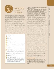
SECTION 1 - How to use this manual> Welcome > GeneralWELCOMEThank you for choosing a <strong>neo</strong> rooflight. We are sure that <strong>neo</strong> will provide a high-quality finishing touch to yourproject. This guide is intended to assist building contractors and homeowners in receiving, handling and installing<strong>the</strong> <strong>neo</strong> rooflight. Please take <strong>the</strong> time to read and carefully follow <strong>the</strong>se instructions. Particular attention should bepaid to <strong>the</strong> ‘Important Information’ section at <strong>the</strong> back of this installation guide.GENERALPlease note: <strong>the</strong> minimum roof angle at which <strong>neo</strong> can be installed is 20 degrees.Please note: <strong>the</strong> maximum roof angle at which <strong>neo</strong> can be installed is 70 degrees.Please note: <strong>the</strong> following installation details pertain to COLD ROOF construction andSLATE tile type. Some installation details may vary depending on <strong>the</strong> roof constructionand tile type being used. Always view this manual in conjunction with <strong>the</strong> cross sectionalinstallation details relevant to your project. See <strong>the</strong> section ‘Suggested installation details’in this manual.Use <strong>the</strong> ‘Contents’ section to access <strong>the</strong> specific information you need to install <strong>the</strong> rooflight. In order to access <strong>the</strong>information you require in order to install <strong>neo</strong> you will need to know:1. <strong>The</strong> <strong>neo</strong> rooflight model to be installed.2. <strong>The</strong> type of roof construction to be used, e.g. warm roof or cold roof.3. <strong>The</strong> type of roof tile to be used, e.g. clay tiles, slate, interlocking tile, pantile, zinc or lead sheet, etc.4. <strong>The</strong> thickness of <strong>the</strong> roof finishes from <strong>the</strong> top of structural rafters to <strong>the</strong> general line of <strong>the</strong> top of <strong>the</strong> rooffinishes.TEXT- Highlighted in BOLD indicates a point of special importance.3
SECTION 1 - How to use this manual> Contentsq ContentsqPageSECTION 1 - How to use this manual 3SECTION 2 - Prior to installation 5SECTION 3 - Structural opening sizes 6SECTION 4 - Preparing <strong>the</strong> roof 7SECTION 5 - Installing <strong>the</strong> rooflight 16SECTION 6 - Finishing <strong>the</strong> interior 22SECTION 7 - Suggested installation details 23SECTION 8 - Important Information 284
SECTION 2 - Prior to installation> Receiving <strong>the</strong> rooflight > Transport & storageSingle rooflight as deliveredrecyclable doublednylon binding toallow <strong>the</strong> box to beretied toge<strong>the</strong>rrecyclablecardboardpackingRECEIVING THE ROOFLIGHTUNLESS <strong>the</strong> packaging is completely undamagedwe recommend that <strong>the</strong> rooflight packaging istemporally opened to allow inspection of <strong>the</strong>goods for damage. Follow <strong>the</strong> instructions on <strong>the</strong>delivery checking and advice label.uOnce <strong>the</strong> rooflight has been checked,repackage it in <strong>the</strong> original packaging for safestorage until <strong>the</strong> rooflight is to be installed.product ID& transportinformationTRANSPORT & STORAGEdelivery &checking adviceuOne set of nylon banding is doubled in eachdirection to allow sufficient material to retie <strong>the</strong>packaging toge<strong>the</strong>r.uuuKeep <strong>the</strong> rooflight in its original packaging and store off <strong>the</strong> ground in a secure covered dry place until it isrequired for installation.When transporting <strong>the</strong> rooflight in its box, carry <strong>the</strong> box by lifting it from <strong>the</strong> underside ra<strong>the</strong>r thanlifting by its strapping.Stack multiple units carefully and only as many units high as is set out on <strong>the</strong> transport informationlabel on <strong>the</strong> box.uuOnly remove <strong>the</strong> rooflight from its packaging when it is required for installation.Once unpacked carry <strong>the</strong> rooflight by lifting it from <strong>the</strong> underside of <strong>the</strong> baseplate.uMark <strong>the</strong> original box with <strong>the</strong> window number/location and keep all accessories and linings in <strong>the</strong> original boxuntil <strong>the</strong>y are required. When <strong>the</strong> installation is complete and all accessories/linings are used, recycle all of <strong>the</strong>packaging materials.store in a covereddry secure areado not stack too highor allow to get wet5
SECTION 3 - Structural opening sizes> Tile type: Slate and Clay tilesTILE TYPE: SLATE AND CLAY TILESTo derive <strong>the</strong> structural framing dimensions for <strong>neo</strong> you will need to have <strong>the</strong> following information to hand:uu<strong>The</strong> <strong>neo</strong> model reference number to be installed.<strong>The</strong> type of roof construction to be used e.g. cold or warm.Follow <strong>the</strong> appropriate information pathway to derive <strong>the</strong> structural framing dimensions below.Cold roof construction type<strong>Rooflight</strong>modelStructural framingdimensionsWidth (mm) x Length (mm)structuralopening<strong>neo</strong> 38P<strong>neo</strong> 57P<strong>neo</strong> 63P<strong>neo</strong> 94P<strong>neo</strong> 150P907 x 1412907 x 18071062 x 16071062 x 21021387 x 2187<strong>neo</strong> 63L<strong>neo</strong> 94L<strong>neo</strong> 150L1402 x 12671897 x 12671982 x 1592Cold Roof -Insulation is between <strong>the</strong> rafters<strong>neo</strong> 41S<strong>neo</strong> 93S1062 x 12671387 x 1592Warm roof construction type<strong>Rooflight</strong>modelStructural framingdimensionsWidth (mm) x Length (mm)structuralopening<strong>neo</strong> 38P<strong>neo</strong> 57P<strong>neo</strong> 63P<strong>neo</strong> 94P<strong>neo</strong> 150P687 x 1007687 x 1402842 x 1202842 x 16971167 x 1782<strong>neo</strong> 63L<strong>neo</strong> 94L<strong>neo</strong> 150L1182 x 8621677 x 8621762 x 1187Warm roof -Insulation is on top of <strong>the</strong> rafters<strong>neo</strong> 41S<strong>neo</strong> 93S842 x 8621167 x 11876
SECTION 4 - Preparing <strong>the</strong> roof> Structural framing and support around <strong>the</strong> rooflightSTRUCTURAL FRAMINGS AND SUPPORTS AROUND THE ROOFLIGHTIntroduction.<strong>The</strong>re are two main tasks to be undertaken to provide an opening in <strong>the</strong> roof and structural supports for <strong>neo</strong>.1. Forming <strong>the</strong> Structural Opening.2. Installing <strong>the</strong> Structural Bearers.uu<strong>The</strong> first task undertaken in all installations, whe<strong>the</strong>r to a new or existing roof, is formation of a structural opening.Go to page 8<strong>The</strong> second task is installation of structural bearers within <strong>the</strong> formed structural opening.Go to page 10Ply linings:Cold roof - Ply linings are required between <strong>the</strong> structural supports and structural bearers in all cold roofinstallations. See section ‘Suggested installation details’ in this manual.Warm roof - Ply linings are required to be fixed outside <strong>the</strong> structural bearers in all warm roof installations. Seesection ‘Suggested installation details’ in this manual.1. Forming <strong>the</strong> structural openinggo to page 82. Installing <strong>the</strong> structural bearersgo to page 107
SECTION 4 - Preparing <strong>the</strong> roof> Forming <strong>the</strong> structural openingsFORMING THE STRUCTURAL OPENINGuForming a structural opening in a roof for a <strong>neo</strong> is straightforward. <strong>The</strong> opening is formed using structuralmembers which re-route structural loads from <strong>the</strong> roof above around <strong>the</strong> structural opening.Note: All structural member sizing and fixings around <strong>the</strong> structural opening are to be asdetailed by <strong>the</strong> Project Architect/Structural Engineer. Our drawings are indicative only.uWhere <strong>neo</strong> is to be installed in a new roof <strong>the</strong> structural members can be designed to reduce <strong>the</strong> necessity forcutting and trimming.uWhere <strong>neo</strong> is to be installed in an existing roof <strong>the</strong> structural opening may require additional structural membersto be inserted and/or existing members cut and re-supported in order to facilitate installation in <strong>the</strong> locationrequired.<strong>neo</strong> - in a new roof<strong>neo</strong> - in an existing rooftrimmed rafterclearstructuralwidthtrimmingraftersjambstructuralsupportsnew trimmingrafters addednew structuralsupport rafterclearstructuralwidthremoved raftersectionclearstructurallengthclear structurallengthtrimming raftersnew structuralsupport rafternew trimmingrafters added8
SECTION 4 - Preparing <strong>the</strong> roof> Height of <strong>the</strong> structural bearers > Installing <strong>the</strong> structural bearersHEIGHT OF THE STRUCTURAL BEARERS<strong>The</strong> intention of this installation guide is to achieve an installation of <strong>neo</strong> that presents <strong>the</strong> glazing nominally flushto <strong>the</strong> general level of <strong>the</strong> top of <strong>the</strong> roofing material. Such an install achieves <strong>the</strong> inconspicuous appearancecharacteristic of <strong>neo</strong>.It is most important that installers read and apply <strong>the</strong> contents of this section.INSTALLING THE STRUCTURAL BEARERSIn all installations <strong>neo</strong> sits on structural bearers once installed. <strong>The</strong> positioning of <strong>the</strong> structural bearers is dependant on:u Roof type (e.g. cold or warm roof)u Roof finish (e.g. slate, clay tile etc)For flush installation <strong>the</strong> top of <strong>the</strong> structural bearers needs to be located 110mm below <strong>the</strong> general line of <strong>the</strong>roof finish. For cold roof installation <strong>the</strong> structural bearers need to be 100mm minimum height in order toaccommodate <strong>the</strong> rooflight baseplate within <strong>the</strong> roof cavity.Please see <strong>the</strong> worked examples below.Cold roofgeneral line of<strong>the</strong> roof finishWarm roofgeneral line ofroof finishWBP or marineply liningA110mm110mm100mmMINABstructuralbearersstructuralbearersWBP or marineply liningCsection at jambsection at jambCOLD ROOF(A) Thickness of roof finish (this is <strong>the</strong> dimension from <strong>the</strong> top of <strong>the</strong>structural supports to <strong>the</strong> general line of <strong>the</strong> roof finish)(B) <strong>The</strong> depth <strong>the</strong> bearers sit below <strong>the</strong> structural memberWARM ROOF(A) Thickness of roof finish (this is <strong>the</strong> dimension from <strong>the</strong> top of <strong>the</strong>structural supports to <strong>the</strong> general line of <strong>the</strong> roof finish)(C) <strong>The</strong> height <strong>the</strong> bearers sit above <strong>the</strong> structural memberIn this example A = 50mm (25mm batten + 25mm slate)<strong>The</strong> top surface of <strong>the</strong> bearers is required to be 110mm below <strong>the</strong>general line of <strong>the</strong> roof finish.Where:B = 110 – A<strong>The</strong>refore: B = 110 – 50 B = 60mm (in this example)In this example A = 175mm (100mm insulation + 25mm counterbatten + 25mm batten + 25mm slate)<strong>The</strong> top surface of <strong>the</strong> bearers is required to be 110mm below <strong>the</strong>general line of <strong>the</strong> roof finish.Where: C = A - 110<strong>The</strong>refore: C = 175 – 110 C = 65mm (in this example)9
SECTION 4 - Preparing <strong>the</strong> roof> Installing <strong>the</strong> structural bearers - Jambs and HeadINSTALLING THE STRUCTURAL BEARERS - JAMBS AND HEADOnce <strong>the</strong> fixing height of <strong>the</strong> structural bearers is derived <strong>the</strong>y can be fixed to <strong>the</strong> main structural supports.COLD ROOF: <strong>The</strong> structural bearers at <strong>the</strong> HEAD and JAMBS of <strong>the</strong> structural opening are to be two 50mm widetimber members. JAMB structural members bearers extend continuously from head to cill and <strong>the</strong> HEAD structuralbearers are cut to fit within <strong>the</strong> jamb structural bearers. We recommend use of threaded rod fixings with largerecessed washers and locknuts as shown below. Locating fixings at centres as specified by <strong>the</strong> project StructuralEngineer.WARM ROOF: <strong>The</strong> structural bearers at <strong>the</strong> HEAD and JAMBS of <strong>the</strong> structural opening are to be 100mm wideand fixed directly on top of <strong>the</strong> structural support and trimming rafters. JAMB structural members bearers extendcontinuously from head to cill and <strong>the</strong> HEAD structural bearers are cut to fit within <strong>the</strong> jamb structural bearers asshown below. Fixing type and spacing to as specified by <strong>the</strong> project Structural Engineer.Cold RoofJamb & HeadWarm RoofJamb & Head1.2.3.1.COLD ROOFOn ‘thin’ roof constructions such as cold roof, <strong>neo</strong> is installedbetween <strong>the</strong> structural supporting rafters.<strong>The</strong> structural bearers should be strongly fixed to <strong>the</strong>ir flankingstructural supports (see note above).Fixing components:1. locknut2. threaded bar3. washerWARM ROOFOn ‘thicker ‘ roof constructions such as warm roof, <strong>neo</strong> is installedon top of <strong>the</strong> structural supporting rafters.<strong>The</strong> structural bearers require to be strongly screwed down onto<strong>the</strong> structural supports. For larger <strong>neo</strong> rooflights consider usingstainless steel brackets in addition to screw fixings.1. screw fixings as specified by projects Structural Engineer10
SECTION 4 - Preparing <strong>the</strong> roof> Prepared opening > Tilting filletpPrepared OpeningTrim <strong>the</strong> opening within <strong>the</strong> roof to <strong>the</strong> correct size required for<strong>the</strong> model of rooflight being installed.Install <strong>the</strong> cill tilting fillet (we recommend hardwood or treatedsoftwood). Its purpose is to support <strong>the</strong> cill flashing andflashing substrate. Note: Details shown here are for COLDROOF construction. See section ‘suggested installationdetails’ in this manual for appropriate WARM ROOF detail.qInstalling <strong>the</strong> cill tilting fillet12
SECTION 4 - Preparing <strong>the</strong> roof> Tilting fillet > <strong>Rooflight</strong> membranepInstalling <strong>the</strong> head tilting filletInstall <strong>the</strong> head tilting fillet as shown (we recommendhardwood or treated softwood).Fold and trim <strong>the</strong> roofing membrane around <strong>the</strong> structuralopening as shown. If battening at this stage lightly tack <strong>the</strong>battens at <strong>the</strong> jambs only.qTrim & finish <strong>the</strong> roofing membrane13
SECTION 4 - Preparing <strong>the</strong> roof> Roofing membrane tray > Cill flashing substratepRoofing membrane trayInstall a roofing membrane tray at <strong>the</strong> cill of <strong>the</strong> opening asshown. <strong>The</strong> membrane tray is to pass over <strong>the</strong> cill tilting filletand terminate over <strong>the</strong> general roofing membrane.Install a 15mm thick WBP or marine-quality ply flashingsubstrate at <strong>the</strong> cill of <strong>the</strong> opening as shown. It is to beinstalled over <strong>the</strong> membrane tray shown above and ofsufficient length to ensure that <strong>the</strong> cill flashing finishes at <strong>the</strong>height of <strong>the</strong> cill rooftiles. Ensure a 5mm MIN gap between<strong>the</strong> 2 halves of <strong>the</strong> substrate.qCill flashing substrate14
SECTION 4 - Preparing <strong>the</strong> roof> Battening up to <strong>the</strong> cill > Battening up to <strong>the</strong> jambspBattening up to <strong>the</strong> cillIt is recommended that <strong>the</strong> roof is battened up to <strong>the</strong> cill of <strong>the</strong>opening at this stage. Ensure that <strong>the</strong> roofing membrane traywhich was previously fitted is located underneath <strong>the</strong> battens.Batten spacing is determined by <strong>the</strong> roof covering being used.Adjust <strong>the</strong> battening and tiling to course and fit around <strong>the</strong>structural opening.When battening around <strong>the</strong> opening <strong>the</strong> battens at <strong>the</strong> jambsare to come up to <strong>the</strong> outside faces of <strong>the</strong> structural opening(COLD ROOF) as shown. Whilst installing <strong>the</strong>se make surethat <strong>the</strong> ends of <strong>the</strong> battens are only ‘tacked’ in place at thisstage. This is to ensure <strong>the</strong> rooflight is wea<strong>the</strong>red in correctlyat a later stage of <strong>the</strong> installation.qBattening up <strong>the</strong> jambs15
SECTION 5 - Installing <strong>the</strong> rooflight> Lead cill flashing > Installing <strong>the</strong> rooflightpLead cill flashingInstall a code 3-5 lead flashing (depending upon <strong>the</strong> wea<strong>the</strong>rexposure) to <strong>the</strong> cill of <strong>the</strong> opening as shown. Side lap to beminimum 150mm. Length of flashing to be sufficient to give<strong>the</strong> tile-recommended headlap. Lay a continuous thick beadof low-modulus neutral cure silicone along <strong>the</strong> flashing.Lift <strong>the</strong> rooflight into <strong>the</strong> opening being careful NOT to pick <strong>the</strong>rooflight up by <strong>the</strong> perimeter extrusion or cill flashing.If your rooflight model has a motorised configuration, be sureto allow enough room <strong>the</strong> cill of <strong>the</strong> rooflight for <strong>the</strong> cable toescape <strong>the</strong> frame without becoming trapped or over-twisted.qInstalling <strong>the</strong> rooflight16
SECTION 5 - Installing <strong>the</strong> rooflight> Fixing <strong>the</strong> rooflight > Perimeter silicone filletpFixLocate all of <strong>the</strong> fixing points at <strong>the</strong> perimeter of <strong>the</strong> rooflight. Drillpilot holes and fix <strong>the</strong> coach bolts with a large flat washer and a springwasher through and into <strong>the</strong> structural bearers. ONLY TIGHTEN THECOACH BOLTS UNTIL THE SPRING WASHER HAS FLATTENEDOUT. OVER TIGHTENING OF THE COACH BOLTS CAN CAUSEDAMAGE TO THE ROOFLIGHT FRAME. Ensure all marked fixingpoints are used.Install a thick continuous fillet of low-modulus neutral curesilicone to full length and width of <strong>the</strong> jambs and head of <strong>the</strong>rooflight perimeter as shown.qPerimeter silicone fillet17
SECTION 5 - Installing <strong>the</strong> rooflight> Installing <strong>the</strong> jamb flashing > Installing <strong>the</strong> head flashingImage BImage A‘CLICK’Image CN.B. <strong>Installation</strong> of <strong>the</strong>jamb flashing can befacilitated by opening<strong>the</strong> rooflight casement(model dependent).pInstalling <strong>the</strong> jamb flashingOrientate <strong>the</strong> jamb flashing over <strong>the</strong> jamb extrusion as shown in imageA. Grasp <strong>the</strong> extrusion in <strong>the</strong> middle and pull <strong>the</strong> flashing back toward<strong>the</strong> rooflight slowly until it clicks (image B). Next push <strong>the</strong> flashing backoutward toward <strong>the</strong> battens to engage <strong>the</strong> flashing onto <strong>the</strong> extrusion(image C). Ensure <strong>the</strong> flashing bites onto <strong>the</strong> rooflight extrusion - push<strong>the</strong> top and bottom of <strong>the</strong> flashing into place. <strong>The</strong> excess felt on <strong>the</strong> jambflashing should be positioned toward <strong>the</strong> head of <strong>the</strong> rooflight as shown.<strong>The</strong> felt attached to <strong>the</strong> jamb flashings should go OVER <strong>the</strong>general roofing membrane but UNDER <strong>the</strong> battens which maybe in place. Repeat for <strong>the</strong> opposing side. Next, lay <strong>the</strong> headflashing over <strong>the</strong> head fillet. Fold, boss and tuck <strong>the</strong> flashing backinto <strong>the</strong> baseplate rollover. <strong>The</strong>re may be a requirement to trim<strong>the</strong> head flashing around <strong>the</strong> jamb battens depending upon <strong>the</strong>irpositioning.qInstall <strong>the</strong> head flashing18
SECTION 5 - Installing <strong>the</strong> rooflight> Installing <strong>the</strong> head roofing membrane > Wea<strong>the</strong>ringpInstall <strong>the</strong> head roofing membraneLay <strong>the</strong> strip of roofing felt over <strong>the</strong> head flashing and ensure ittucks UNDER <strong>the</strong> next lap in <strong>the</strong> general roofing membrane.<strong>The</strong> combination of <strong>the</strong> head flashing and <strong>the</strong> roofing felt beinglapped in this way, ensures moisture will run up and over <strong>the</strong>tilting fillet, onto <strong>the</strong> baseplate and finally off <strong>the</strong> roof.qWea<strong>the</strong>ring19
SECTION - Installing <strong>the</strong> rooflight> Tiling <strong>the</strong> jambsSECTION 5 - Installing <strong>the</strong> rooflight> Complete <strong>the</strong> tiling> Tiling <strong>the</strong> jambs > Complete <strong>the</strong> tilingpTile <strong>the</strong> jambsTile <strong>the</strong> jambspUse <strong>the</strong> edge of <strong>the</strong> jamb flashing as a guide to tile up to and tile<strong>the</strong> jambs. Use Ensure <strong>the</strong> edge <strong>the</strong> of wea<strong>the</strong>ring jamb flashing foam attached as a guide to <strong>the</strong> to tile jambup to andflashings tile is <strong>the</strong> folded jambs. down Ensure and away <strong>the</strong> wea<strong>the</strong>ring from rooflight foam attached when layingto <strong>the</strong><strong>the</strong> tiles.jamb flashings is folded down and away from <strong>the</strong> rooflightwhen laying <strong>the</strong> tiles.<strong>The</strong> head of <strong>the</strong> rooflight can now be tiled.. We recommend <strong>the</strong> useof <strong>The</strong> eaves head tiles. of Complete <strong>the</strong> rooflight <strong>the</strong> can tiling now around be tiled.. <strong>the</strong> We head recommend of <strong>the</strong> rooflightaccordingly.<strong>the</strong> use of eaves tiles. Complete <strong>the</strong> tiling around <strong>the</strong> head of<strong>the</strong> rooflight accordingly.qComplete <strong>the</strong> tilingComplete <strong>the</strong> tiling2121
®®SECTION SECTION - Finishing 6 <strong>the</strong>- Finishing interior<strong>the</strong> interior> InstallingInstalling <strong>the</strong><strong>the</strong> headhead andand cillcill liningslinings> Installing <strong>the</strong> head and cill linings > Installing <strong>the</strong> jamb linings> InstallingInstalling <strong>the</strong><strong>the</strong> jambjamb liningsliningspBaseplateBaseplate liningslinings-HeadHead Head andand and CillCill CillInstall <strong>the</strong> cill and head linings as shown. Orientate <strong>the</strong> liningInstall <strong>the</strong> <strong>the</strong> cill cill and and head head linings linings as shown. as shown. Orientate Orientate <strong>the</strong> lining <strong>the</strong> liningwith <strong>the</strong> fixing holes aligned to <strong>the</strong> securing brackets located inwith with <strong>the</strong> <strong>the</strong> fixing fixing holes holes aligned aligned to <strong>the</strong> to <strong>the</strong> securing securing brackets brackets located located in<strong>the</strong> rooflight baseplate recess. (as shown by <strong>the</strong> dashed line in <strong>the</strong><strong>the</strong> in rooflight <strong>the</strong> rooflight baseplate baseplate recess. recess. (as shown (as shown by <strong>the</strong> dashed by <strong>the</strong> dashed line in <strong>the</strong> lineabove image). Secure in place using screws provided. Cover <strong>the</strong>above in <strong>the</strong> image). above Secure image). in Secure place using place screws using provided. screws Cover provided. <strong>the</strong>screw heads by inserting <strong>the</strong> timber plugs until flush to <strong>the</strong> surfacescrew Cover heads <strong>the</strong> screw by inserting heads <strong>the</strong> by timber inserting plugs <strong>the</strong> until timber flush plugs to <strong>the</strong> until surface flushof <strong>the</strong> lining.of to <strong>the</strong> <strong>the</strong> lining. surface of <strong>the</strong> lining.Install <strong>the</strong> jamb linings as shown. <strong>The</strong> installation method is <strong>the</strong>Install <strong>the</strong> jamb linings as as shown. <strong>The</strong> <strong>The</strong> installation method method is <strong>the</strong> issame as that used for <strong>the</strong> head and cill linings.same <strong>the</strong> same as that as used that for used <strong>the</strong> for head <strong>the</strong> and head cill and linings. cill linings.qBaseplateBaseplate liningslinings - JambJamb - 2222 22
SECTION 7 - Suggested installation details> Drawing identificationDRAWING IDENTIFICATIONSLATE ROOF FINISHCold roof construction drawing number: NE_100INSTWarm roof construction drawing number: NE_101INSTPage2425CLAY TILE ROOF FINISHCold roof construction drawing number: NE_102INSTWarm roof construction drawing number: NE_103INST262723
SECTION 8 - Important Information> Maintenance > Guarantee > AdvisoryCare & MaintenanceTo achieve <strong>the</strong> maximum service life from <strong>neo</strong> it is important that scheduled care and maintenance is undertaken.<strong>The</strong> following procedures are to be performed at least every six months, and more frequently in exposed or marinelocations.uuu<strong>Rooflight</strong> cleaning – Clean <strong>neo</strong>’s glass, baseplate and casement, in particular <strong>the</strong> exposed external surfaces.Clean <strong>the</strong> baseplate and casement with warm water containing a weak solution of car wash fluid using a naturalbristle brush, and rinse with clean water.Before cleaning, clear <strong>the</strong> exterior of <strong>the</strong> rooflight of any debris that may have collected. Excessive buildup ofleaves, twigs, roof tile chips, etc can cause <strong>the</strong> rooflight to leak. Fur<strong>the</strong>rmore chemicals contained within <strong>the</strong>debris can have a detrimental effect on <strong>the</strong> paintwork finishes.Glass cleaning - On models of <strong>neo</strong> in which <strong>the</strong> casement can open to 90º (see ‘<strong>Rooflight</strong> weights and openingangle’) it is possible to clean <strong>the</strong> glass from <strong>the</strong> inside. On models that cannot achieve 90º casement openingcleaning can be effected from inside using a cleaning tool obtainable from <strong>the</strong> <strong>Rooflight</strong> <strong>Company</strong>. When cleaningfrom <strong>the</strong> inside ensure <strong>the</strong> casement is securely held open and do not put arms or hands through any of <strong>the</strong>moving parts.Gas strut maintenance - <strong>The</strong> gas struts that assist in <strong>the</strong> opening of <strong>the</strong> rooflight require to be operated at leastonce a month. This keeps <strong>the</strong> seals lubricated and helps ensure that pressure is maintained. <strong>The</strong> gas strutsshould also be kept clean and free of dirt - especially <strong>the</strong> piston rod. Wipe <strong>the</strong> piston rod with a clean dry greasefreecloth or a piece of clean kitchen towel.AdvisoryStandard rooflight: All <strong>the</strong> information provided in this document refers to a standard specification <strong>neo</strong> rooflight.Install in accordance with this manual: <strong>The</strong> <strong>Rooflight</strong> <strong>Company</strong> cannot accept any liability if <strong>neo</strong> is not installedstrictly in accordance with <strong>the</strong> instructions contained in this manual and implicit in <strong>the</strong> ‘Suggested <strong>Installation</strong>Details’.Structural support: Structural supports for <strong>neo</strong> are to be designed and supervised during construction by <strong>the</strong>rooflight installer’s or project Structural Engineer.Gas struts: <strong>neo</strong> has integral gas struts which assist <strong>the</strong> opening casement and support it when fully open. <strong>The</strong> gasstruts are highly pressured and care is required when operating <strong>the</strong>m. Do not attempt to adjust or dismantle <strong>the</strong>m.28
SECTION 8 - Important Information> <strong>Rooflight</strong> weight and opening angle > Fur<strong>the</strong>r Information<strong>Rooflight</strong> weights and opening angleWhen handling and installing <strong>neo</strong> its weight should be considered and adequate means employed to move <strong>the</strong>rooflight into position to reduce <strong>the</strong> risk of accidents..<strong>Rooflight</strong>modelApproximatecasementweight(kg)Approximatebaseplateweight(kg)Maximumopeningangle*(degrees)<strong>neo</strong> 38P<strong>neo</strong> 57P<strong>neo</strong> 63P<strong>neo</strong> 94P<strong>neo</strong> 150P2836374965263131384390505030N/A<strong>neo</strong> 63L<strong>neo</strong> 94L<strong>neo</strong> 150L3749653138439090N/A<strong>neo</strong> 41S<strong>neo</strong> 93S284726359090Fur<strong>the</strong>r InformationAll of <strong>the</strong> images in this guide are diagrammatic (with some components omitted for clarity). <strong>The</strong>y should be used asa reference and may not be a true representation of <strong>the</strong> installation.<strong>Installation</strong> instructions are regularly reviewed and we reserve <strong>the</strong> right to update or amend <strong>the</strong>se details withoutalteration to this guide.* Please note: opening angles are approximate and may be slightly less than stated, due to <strong>the</strong> effect of gas springbalancing. Where ‘N/A’ is shown - rooflight models are fixed closed and do not open.June 201029
30NOTES
NOTES31
A trading name of <strong>the</strong> Metal Window <strong>Company</strong> Ltd.Wychwood Business CentreMilton RoadShipton-under-WychwoodOX7 6XUTel: 01993 833 108Fax: 01993 831 066Email: info@<strong>the</strong>rooflightcompany.co.ukWeb: www.<strong>the</strong>rooflightcompany.co.uk<strong>The</strong> <strong>neo</strong> rooflight is a registered trademark of <strong>The</strong> Metal Window <strong>Company</strong> Ltd.In <strong>the</strong> interest of continuous product development, it may be necessary to amend specification without alteration to technical literature.All drawings and designs are <strong>the</strong> Copyright and Designright of <strong>The</strong> Metal Window <strong>Company</strong> Ltd.