DUCTILE UNDERCUT ANCHORS - USP Connectors
DUCTILE UNDERCUT ANCHORS - USP Connectors
DUCTILE UNDERCUT ANCHORS - USP Connectors
- No tags were found...

Create successful ePaper yourself
Turn your PDF publications into a flip-book with our unique Google optimized e-Paper software.
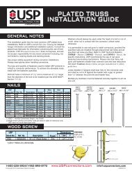
<strong>DUCTILE</strong> <strong>UNDERCUT</strong> <strong>ANCHORS</strong>DUCTILITY • SAFETY • PERFORMANCE
How it WorksDUC Undercut AnchorAdvantagesThe DUC Undercut Anchor consists of an ASTM A36or A193 Grade B7 threaded stud, a thick-walled expansionsleeve, an expander coupling and a nut andwasher (316 stainless steel is also available).The DUC Undercut Anchor is installed into apre-drilled hole which has been enlarged at thebottom in the shape of a reversed cone. The reversecone is created using the <strong>USP</strong> DUC Undercutting Bit.The DUC Undercutting Bit fits into SDS or SDS Maxrotary hammer drills and guarantees the correctangle of the reverse cone. The anchor is expandedinto the reverse cone when the expansion sleeve isdriven over the expander coupling.The result is an anchor which transfers load mainlythrough bearing, and unlike a typical expansionanchor (sleeve, heavy duty sleeve, wedge anddrop-ins), the DUC is not dependent upon frictionbetween the expansion sleeve and the concrete. Dueto the use of a thick walled expansion sleeve, the loadis distributed to a large area which ensures ductilebehavior of the anchor even at relatively shallowembedments.Compared with heavy capacity sleeve and expansionanchors and other undercut systems:• DUC Undercut design provides consistent expansionand is easy to set. Stress risers have been eliminatedto prevent tearing.• Large bearing area provides exceptionalperformance even in low strength concrete.• Load transfers mainly through bearing, not expansionforces. They are not dependent upon friction whichcan be lost when cracks occur.• Thick walled sleeves transfer load over a larger areawhich insures predictable ductile performance.• ASTM A36 or A193 grade B7 rods are used. Fullultimate steel strength is developed at listed embedmentand spacing. Stainless steel also available.• Installation is simple. It is similar to installing atypical expansion anchor; no coring drills arenecessary. Creation of proper undercut is correctlydone and easily verified using DUC Undercut Bits.Creation of undercut takes only seconds.The DUC Undercut Anchors have been tested in accordance with ACI355.2 to be qualified for use with the design methods of ACI 318appendix D, including recognition in cracked concrete.Available Anchor Sizes38-275L38-275LT38-400H38-400HT12-400L12-400LT12-500H12-500HT12-675H12-675HT58-450L58-450LT58-750H58-750HT58-900H58-900HT34-500L34-500LT34-1000H34-1000HT
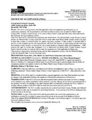
Ductile Undercut (DUC) Undercut AnchorInstallation Instructions12 3 4 5 6 7*Images not at equal scaleStop Drill BitThe DUC Undercut Anchor behaves nearly identicallyto a cast-in-place bolt. The standard embedmentslisted ensure that the capacity of theconcrete exceeds that of the steel at the listedspacings and edge distances.The capacity of DUC anchors can be calculatedusing Section 1923 of the 1997 UBC or AppendixD of ACI 318 for the IBC. Capacities for closespacing, edge conditions, and cracked concretecan be calculated using the provisions of ACI 318Appendix D.Stop Drill BitDesignationStop Drill Bit DimensionsCorresponding AnchorCatalog NumberMaximum DrillingDepth, t (inches)dbit(inches)ShankTypeDUCSB38-275 DUC38-275 3-1/4 5/8 SDSDUCSB38-400 DUC38-400 4-1/2 5/8 SDSDUCSB12-400 DUC12-400 4-9/16 3/4 SDSDUCSB12-500 DUC12-500 5-9/16 3/4 SDSDUCSB12-675 DUC12-675 7-5/16 3/4 SDSDUCSB58-450 DUC58-450 5-7/16 1 SDS-MaxDUCSB58-750 DUC58-750 8-7/16 1 SDS-MaxDUCSB58-900 DUC58-900 9-9/16 1 SDS-MaxDUCSB34-500 DUC34-500 6 1-1/8 SDS-MaxDUCSB34-1000 DUC34-1000 11 1-1/8 SDS-MaxFor SI: 1 inch = 25.4 mm.
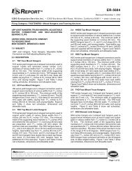
City of Los Angeles Research Report No. 25113 ICC ES ESR 1970Installation Details and Allowable Loads for DUC Undercut AnchorsCatalogNo.Stud dia.d bSleeve dia.d sDrill holedia. d bitDrill holedepth teffectiveembed.h efMaxfasteningthickness t fixOverallLength, l bSleevelength l sAllowableTensileCapacity, N sAllowableshearcapacity V s38-275L 3/8 5/8 5/8 3-1/8 2 3/4 1-3/4 6 2-3/4 2087 104338-275LT 3/8 5/8 5/8 3-1/8 2 3/4 1-3/4 6 4-1/2 2087 104338-400H 3/8 5/8 5/8 4-3/8 4 1-3/4 7-1/2 4 4497 225438-400HT 3/8 5/8 5/8 4-3/8 4 1-3/4 7-1/2 5-3/4 4497 225412-400L 1/2 3/4 3/4 4-3/8 4 1-3/4 7-1/2 4 3821 190912-400LT 1/2 3/4 3/4 4-3/8 4 1-3/4 7-1/2 5-3/4 3821 190912-500H 1/2 3/4 3/4 5-3/8 5 1-3/4 8-1/2 5 8235 411112-500HT 1/2 3/4 3/4 5-3/8 5 1-3/4 8-1/2 6-3/4 8235 411112-675H 1/2 3/4 3/4 7-1/8 6 3/4 1-3/4 10-1/4 6-3/4 8235 411112-675HT 1/2 3/4 3/4 7-1/8 6 3/4 1-3/4 10-1/4 8-1/2 8235 411158-450L 5/8 1 1 5-1/8 4 1/2 1-3/4 8-3/8 4-1/2 6086 304758-450LT 5/8 1 1 5-1/8 4 1/2 1-3/4 8-3/8 6-1/4 6086 304758-750H 5/8 1 1 8-1/8 7 1/2 1-3/4 11-3/8 7-1/2 13116 655258-750HT 5/8 1 1 8-1/8 7 1/2 1-3/4 11-3/8 9-1/4 13116 655258-900H 5/8 1 1 9-5/8 9 1-3/4 13 9 13116 655258-900HT 5/8 1 1 9-5/8 9 1-3/4 13 10-3/4 13116 655234-500L 3/4 1-1/8 1-1/8 5-5/8 5 1-3/4 9 5 9007 449734-500LT 3/4 1-1/8 1-1/8 5-5/8 5 1-3/4 9 6-3/4 9007 449734-1000H 3/4 1-1/8 1-1/8 10-5/8 10 1-3/4 14 10 19411 969234-1000HT 3/4 1-1/8 1-1/8 10-5/8 10 1-3/4 14 11-3/4 19411 9692NOTES:1. The tabulated values are for anchors installed at the specified spacing (s) and edge (c)distances. Spacing and edge distances may be reduced using the provisions of Section1923 of the Uniform Building Code, or ACI 318 Appendix D for the 2003 and 2006 IBC and IRC. 6. Contact <strong>USP</strong> for custom lengths and stainless steel options. UBC Series Undercut Drill BitsLock ReleaseSpanner PositionDrilling DepthCutter BladeCarbide TipUndercutter Bits for DUC Undercut AnchorsCatalogNumberUCB58UCB34UCB100UCB118UCB118LLock Release ScrewUseWithAnchorsDUC38-275LDUCB38-400HDUCB12-400LDUC12-500HDUC58-450LDUC58-750HDUC58-900HDUC34-500LDUC34-1000HDUC34-500LDUC34-1000HStopper SleeveDiam.(inches)ShankTypeMax. DrillingDepth(inches)RequireDrill ImpactEnergy (ft. lbs)5/8 SDS 9 1.63/4 SDS 10-1/4 2.51 SDS 12-1/4 3.21-1/8 SDS-Max 13-1/2 4.01-1/8 SDS-Max 29-1/2 4.0Replacement Parts forDUC Undercutter BitUndercutterDrill BitBow JawReplacementBow JawReplacementCutterbladeUCB12 BJ12 CB12UCB58 BJ58 CB58UCB34 BJ34 CB34UCB78 BJ78 CB78UCB100 BJ100 CB100UCB118 BJ118 CB118UCB118L BJ118L CB118To change the cutter blade or bow jaw, do not loosen the setscrew on the stopper sleeve. Push the detent pin throughthe stopper sleeve from the side opposite the set screw untilit stops. The bow jaw can now be pulled out. Reverse forreassembly.Corporate Office: 14305 Southcross, Burnsville, MN 55306Ph: (800) 328-5934 • Fax: (952) 898-8683www.<strong>USP</strong>connectors.com