Product Information - USP Connectors
Product Information - USP Connectors
Product Information - USP Connectors
- No tags were found...

You also want an ePaper? Increase the reach of your titles
YUMPU automatically turns print PDFs into web optimized ePapers that Google loves.
<strong>Product</strong> Catalog57 th Edition
Table of ContentsCorrosion <strong>Information</strong> ............7-8Design Notes ..................11Installation Notes ...............12<strong>Product</strong> <strong>Information</strong> ................9<strong>Product</strong> Notes .................10Reference Number Index .........6<strong>USP</strong> Index ................... 4-5FastenersSection Overview .............13Bearing Plates .................20Nails. . . . . . . . . . . . . . . . . . . . . . 14-15Wood Screws .............. 16-19LumberLok Screws ..............20Concrete & Masonry <strong>Connectors</strong>Section Overview .......... 21-22Mechanical & Adhesive Anchors ....... . . . . . . ................... 23-26Anchor Bolts ............... 31-33Concrete Form Ties & Wedge. . . . . 30Foundation Anchors ......... 33-35Laminated Beam Seats ..........36Masonry Metals ............. 27-29Adjustable Support Posts ..... 37-39HoldownsSection Overview .............40Concrete Angles ...............46Foundation Straps ........... 46-49Holdowns .................. 41-44Purlin Anchors .................50Tension Ties ..................45Caps & BasesSection Overview .............51Column Bases .............. 55-56Column Caps ............... 60-63Composite Post Bases ..........59Elevated Post Bases ............54Post Anchors ...............52, 55Post Caps ................. 57-59Wet Post Anchors ..............53Angles & StrapsSection Overview .......... 64-65Coiled Strapping ...............76Framing Clips .................75Framing Plates & Angles .... . .66-70, .72-73Header Hangers ...............75Lateral Joist <strong>Connectors</strong> .........72Masonry Straps ............. 84-85Ornamental <strong>Connectors</strong> .........74Straps .................74, 77-80Stud Plate Ties ................71Twist Straps ................81 -82Wood Foundation Straps. . . . . . . . . 83HangersSection Overview .......... 86-87Face Mount Hangers ......... 88-96Hanger Selector Guide ..........87Masonry Hangers ......... 106-109Top Mount Hangers. . . . . . . . . 97-102Slope & Skew Hangers ..... 103-105Panel & Purlin Hangers ..... 110-112EWP HangersSection Overview ........ 113-115Adjustable <strong>Connectors</strong> .........143EWP Hanger Selector Guide ....113EWP Installation Guide ..... 116-117Face Mount Hangers ....... 118-123Glulam Hangers .......... 145-150Slope/Skew Hangers ...........144Top Mount Hangers. . . . . . . . 124-14 2Truss & Rafter TiedownsSection Overview ............151Truss Anchors ................152Girder Tiedowns .......... 154-156Hurricane Gusset Angles .......158Rafter Ties ............... 160-162Moisture Barrier Plates .........152Uplift Girder Ties ..............153Hurricane Retro-Fit Connector ....159Masonry Uplift Connector .......157Plated TrussSection Overview ........ 163-164Alternate Installations ..........182Blocking Supports .............179Drag Strut <strong>Connectors</strong>. . . . . . . . . . 181Girder Truss Hangers ...... 174-176Hip/Jack <strong>Connectors</strong> ....... 172-173Roof Truss Ties ...............179Skewed Truss Hangers ..... 170-171Supplemental Bearing Plates ....178Truss Clips .............. 176-177Truss Hangers ............ 165-169Truss Spacers ............ 180-181MiscellaneousAngles ......................201Bolt Down ...................189Bridging ................. 183-184Closet Rods ..................202Concealed Stringer Hanger ......194Corner Tie ...................204Deck Clip ....................185Deck Ties ...................193Deck Tie Back ................192Drywall Clip ..................197Fence Brackets ...............190Fence Post <strong>Connectors</strong> .........188Fence Rail Hanger ............196Hardy Frame ............. 206-209Insulation Supports ............203Mending Plates ...............198Nail Plates ...................198Pipe Rail Ties ................191Plastic Post Caps .............204Plywood Clips ................197Protection Plates ..............186Ridge Rafter .................199Shelf Brackets ................203Stair Angles ..................195Step Flashing ................196Stud Shoes ..................189Tough Tie <strong>Product</strong>s ........ 199-200Wall Bracing .................187Wall Ties ....................201Manufactured Housing .......205Lateral Systems ......... 206-209Specialty Options ............210-213Corrosion Resistant <strong>Product</strong>s ... . . . . . . . . . . . . . . . . . . . . . . . 214-215© Copyright 2013 <strong>USP</strong> Structural <strong>Connectors</strong> ®WARRANTYMiTek USA, Inc. (“MiTek”) warrants its <strong>USP</strong> catalog <strong>Product</strong>s to be free from materialdefects in manufacture and design, and further warrants that they will perform within thedesign limitations of its published building code approvals for the applications described,when properly installed and maintained. These warranties do not cover <strong>Product</strong>deterioration due to environmental conditions, <strong>Product</strong>s that have be modified or damaged,improperly installed or used outside of published design limitations or for other applications.In the event any <strong>Product</strong> is shown to not conform to these warranties, <strong>USP</strong>’s soleobligation, and Customer’s sole and exclusive remedy, shall be, at <strong>USP</strong>’s option, to replacethe non-conforming product or refund the full purchase price paid by Customer to <strong>USP</strong>therefor. <strong>USP</strong> MAKES NO OTHER PRODUCT WARRANTIES, EXPRESS OR IMPLIED,OF ANY KIND, AND PARTICULARLY EXCLUDES ANY IMPLIED WARRANTY ORMERCHANTABILITY OR FITNESS FOR A PARTICULAR PURPOSE. IN NO EVENTSHALL <strong>USP</strong> BE LIABLE FOR INCIDENTAL, CONSEQUENTIAL OR SPECIAL DAMAGES,REGARDLESS OF THE LEGAL THEORY OF RECOVERY, EVEN IF IT WAS AWARE OFTHE POSSIBILITY OF SUCH DAMAGES. IN ANY CASE, <strong>USP</strong>’s MAXIMUM LIABILITYSHALL NOT EXCEED THE PURCHASE PRICE PAID BY CUSTOMER FOR THE NON-CONFORMING PRODUCT. Some states restrict consequential or other liability damagelimitations, so some of the above limitations may not apply to you. MiTek reserves the rightto change this warranty periodically. Consult MiTek’s website www.uspconnectors.com orcontact MiTek for a current warranty statement.21-800-328-5934 • www.<strong>USP</strong>connectors.com
The Original Connector Company!HARDYFRAME ®United Steel <strong>Product</strong>s (<strong>USP</strong>) is the leadingmanufacturer of structural connectors andhardware for the building industry. Our legacyof innovation dates back to 1933 when the originaltimber connectors were conceived and standardized.Over the years <strong>USP</strong> has grown by combining someof the most innovative and recognizable structuralbrands into one “UNITED” company that spansthe world. Our lineage includes such brand namesas Teco ® , Silver, Lumberlok, Kant-Sag ® ,Hughes, SEMCO, Covert, and Renown.As of March, 2011 <strong>USP</strong> has been a part of MiTekIndustries, Inc., which is a subsidiary of Warren Buffet’sBerkshire Hathaway. Since, <strong>USP</strong> has expandedits product offering to include the following leadingbrands: Hardy Frame ® shear wall system, Zone4 ®Tie-down system, and Sapphire software suite.With our rich heritage and solid DNA combined withMiTek’s extensive resources and unmatched softwareexpertise, <strong>USP</strong> has become “the connector of choicefor the building industry”.Give your customers a choice!Specify the Original - Specify <strong>USP</strong>!Better Technology. Better Building.A Berkshire Hathaway Company
<strong>USP</strong> Index*A3 Angle Clip . . . . . . . . . . . . . . . .69-70AB Anchor Bolts . . . . . . . . . . . . . . . .33ABP Anchor Bolts . . . . . . . . . . . . . . .33ABS12 Anchor Bolt Stabber . . . . . . .28AC Angle Clips . . . . . . . . . . . . . . .69-70Alternate Installations . . . . . . . . . .182ANJ44S Heavy Angles . . . . . . . . . . .72APB Post Base . . . . . . . . . . . . . . . . .54B Corner Reinforcements . . . . . . . . .73BC Post Caps . . . . . . . . . . . . . . . . . .58BD Bolt Down . . . . . . . . . . . . . . . . .189BL Corner Reinforcements . . . . . . . .73BN Breakfast Nook Hangers . . . . . .172BP Bearing Plates . . . . . . . . . . . . . . .20BPH Beam & Purlin Hangers . . . . . . . .. .124-125, 128-129, 132-136, 138-142C Post Caps . . . . . . . . . . . . . . . . . . . .58CBE Column Bases . . . . . . . . . . . . . .56CBSQ Column Bases . . . . . . . . . . . .55CMST Coiled Strapping . . . . . . . . . . .76CMSTC16 Coiled Strapping . . . . . . .76Corrosion <strong>Information</strong> . . . . . . . . . .7-8Corrosion Resistant <strong>Product</strong>s 214-215CPB Composite Post Bases . . . . . . .59CR Concrete Reinforcing Rods . . . . .27CRE24 Coated Rebar . . . . . . . . . . . .29CRW Closet Rods . . . . . . . . . . . . . .202CRWFP Fluted Closet Rods . . . . . .202CRZ Closet Rods . . . . . . . . . . . . . . .202CRZFP Fluted Closet Rods . . . . . . .202CSH-TZ Concealed Stringer Hanger . . .. . . . . . . . . . . . . . . . . . . . . . . . . . . . .194D Post Anchors . . . . . . . . . . . . . . . . .55DC1 Drywall Clip . . . . . . . . . . . . . . .197DC50 Deck Clip . . . . . . . . . . . . . . .185DSC4 Drag Strut Connector . . . . . .181DT Standard Joist Hanger . . . . . .88, 92DTB Deck Tie Bracket . . . . . . . . . . .192DTUS Undersaddle Hangers . . . . . .111DUC Ductile Undercut Anchors . . . . .25EA Adhesive (CIA-EA) . . . . . . . . . . .24EBG44 Elevated Post Base . . . . . . .54EPB Elevated Post Bases . . . . . . . . .54EPBH Elevated Post Bases . . . . . . .54EPCM End Post Caps . . . . . . . . . . . .57ERB24 Fence Bracket . . . . . . . . . . .190EWP Hanger Selector Guide . . . . .113EWP Installation . . . . . . . . . . .116-117FA3 Foundation Anchors . . . . . . . . . .34FB Fence Brackets . . . . . . . . . . . . .190FC Fence Brackets . . . . . . . . . . . . .190FHD26 Panel Hanger . . . . . . . . . . . .110FPH24-TZ Fence Rail Hanger . . . . .196FRB Fence Brackets . . . . . . . . . . . .190FT Concrete Form Ties . . . . . . . . . . .30FTC Floor Truss Clips . . . . . . . . . . .177*GEL Epoxy (CIA-GEL Series) . . . . .23GHF Glulam Face Mount Hangers .146GT Girder Truss Hangers . . . . .174-175GTD Girder Truss Hangers . . .174-175* GTQ/GTQM Girder Truss Hangers .176GTS Girder Truss Hangers . . . .174-175GTWS Girder Truss Hangers . . . . .175Hanger Selector Guide . . . . . . . . . .87HBPS Bearing Plates . . . . . . . . . . . . 20HC520 Hurricane/Seismic Anchor160,162* HCPRS Rafter Ties . . . . . . . . .160, 162HD Face Mount Hangers . . . . . . . . . . . .. . . . . . . . . . . . . . . .90-96, 118, 122-123HDO Top Mount Hangers . . .97, 99-101HDQIF Inverted Flange Hangers . . . . . .. . . . . . . . . . . . . . . .90, 92-96, 119, 123* HFX Hardy Frame Panels & BraceFrames . . . . . . . . . . . . . . . . . . . . .206HGA Hurricane Gusset Angles . . . .158* HGU Girder Hangers . . . . . . . . . . . 145HH Header Hangers . . . . . . . . . . . . .75HHC Hip/Hip <strong>Connectors</strong> . . . . . . . . .173HHCP2 Hurricane/Seismic Anchor . . . .. . . . . . . . . . . . . . . . . . . . . . . . .160,162HJC Hip/Jack <strong>Connectors</strong> . . . . . . . .173HJHC Hip/Jack <strong>Connectors</strong> . . . . . . .173HL Light Gauge Purlin Hangers . .98-99HLBH Beam Hangers . . . . . . . . . . . . . .. . . . . . . . . . . . .126, 132-136, 138-142**HPAHD Foundation Straps . . . . . .48-49HRS Strap Ties . . . . . . . . . . . . . .77, 79HTC4 Heavy Truss Clip . . . . . . . . . .179HTHJ Hip/Jack <strong>Connectors</strong> . . . . . . 173*HTP Strap Ties . . . . . . . . . . . . . . .77-78HTT Tension Ties . . . . . . . . . . . . . . . .45HTW Twist Straps . . . . . . . . . . . . .81-82HTWM Twist Straps . . . . . . . . . . . . . .85HUGT Girder Tiedowns . . . . . . . . . 156HUS Slant Nail Hangers . . . . . . . . . . . .. . . . . . . . . . . . .89, 91-95, 119, 123,167HWUH Top Flange Hangers . . 106-107ICPL Protection Plates . . . . . . . . . .186IS Insulation Supports . . . . . . . . . . .203JA Framing Angles . . . . . . . . . . . .69-70JDS Purlin Hangers . . . . . . . . . . . . .112JH Multi-Purpose Joist Hangers . . .102JL Standard Joist Hangers . . . . .88, 91JLIF Inverted Flange Hangers . .88, 91JN Power Nail Hangers . . . . . . . . . .205JN(E) Power Nail Hangers . . . . . . .205JNP Mending Plates . . . . . . . . . . . .198JP Adjustable Support Post . . . . . . . .37JPF Purlin Hangers . . . . . . . . . . . . .110JUS Slant Nail Joist Hangers .89, 91-95KB Hanger . . . . . . . . . . . . .97, 100-101KCBQ Column Bases . . . . . . . . . . . .56*****KCCQ Column Caps . . . . . . . . . .60-63KECCQ End Column Caps . . . . .60-63KEG Glulam Beam Hangers . . . . . .147KGB Glulam Hangers . . . . . . . . . . .148KGLB Laminated Beam Seats . . . . .36KGLBT Laminated Beam Seats . . . .36KGLS Glulam Saddle Hangers . . . 150KGLST Glulam Saddle Hangers . . .150KGLT Glulam Beam Hangers . . . . .149KHGB Glulam Hangers . . . . . . . . . .148KHGLB Laminated Beam Seats . . . .36KHGLS Glulam Saddle Hangers . . .150KHGLST Glulam Saddle Hangers . .150KHGLT Glulam Beam Hangers . . . 149KHHB Glulam Hangers . . . . . . . . . .148KHL Corner Framing Angle . . . . . . . .73KHW Top Flange Hangers .98, 100-101KLB Hanger . . . . . . . . . . . . . . . . .97, 99KLEG Glulam Beam Hangers . . . . .147KMEG Glulam Beam Hangers . . . .147KNS1 Protection Plate . . . . . . . . . . .186KRPS Strap Ties . . . . . . . . . . . . . . . .80KSCT68 Corner Tie . . . . . . . . . . . . .204KST Strap Ties . . . . . . . . . . . . . . .77-79KSTI Strap Ties . . . . . . . . . . . . . .77, 79KTS Twist Straps . . . . . . . . . . . . .81-82L Straps . . . . . . . . . . . . . . . . . . . . . . .74LH Strap . . . . . . . . . . . . . . . . . . . . . . .74LL LumberLok Screws . . . . . . . . . . . .20LBP Bearing Plates . . . . . . . . . . . . . .20LBPS Bearing Plates . . . . . . . . . . . . .20LDSC4 Drag Strut Connector . . . . .181LFTA6 Twist Strap . . . .81-82, 160, 162LGU Girder Hangers . . . . . . . . . . . 145LJC-TZ Lateral Joist Connector . . . . 72LJQ Lateral Joist Connector . . . . . . . 72LPTA Embedded Truss Anchors . . 152LS Light Slope Hangers . . . . . . . . .105LSSH Slope/Skew Hangers . .103, 144LSTA Strap Ties . . . . . . . . . . . . . .77-78LSTAD Foundation Straps . . . . . .46-47LSTI Strap Ties . . . . . . . . . . . . . . .77-78LTS Tension Ties . . . . . . . . . . . . . . . .45LTTI31 Tension Tie . . . . . . . . . . . . . .45LTW Twist Straps . . . . . . . . . . . . .81-82LUGT Girder Tiedowns . . . . . . . . . .154MB16 Bridging . . . . . . . . . . . . . . . . .184MBG Bridging . . . . . . . . . . . . . . . . .184MGU Girder Hangers . . . . . . . . . . . 145ML Angles . . . . . . . . . . . . . . . . . . . . 201** *MP Framing Angles . . . . . . . . . . .69-70MP34 Framing Angle . . . . . . . . . .66-67MPA1 Framing Angles . . . . . . . . .66-67* New <strong>Product</strong>s© Copyright 2013 <strong>USP</strong> Structural <strong>Connectors</strong> ®41-800-328-5934 • www.<strong>USP</strong>connectors.com
1-800-328-5934 • www.<strong>USP</strong>connectors.com6© Copyright 2013 <strong>USP</strong> Structural <strong>Connectors</strong> ®Reference Number IndexAbout the Reference NumbersReference numbers shown throughout thecharts in this catalogue are part numberswhich may be more familiar to customers invarious regions of Canada. These areincluded for the convenience of our newcustomers who have recently switched from acompetitor’s product line to <strong>USP</strong>.The reference numbers in this catalogueare for general application comparisononly and should not be used as asubstitution tool. The user is responsibleto compare specific load values, fastenerschedules, material specifications, andother factors to determine suitability ofuse for any particular product.A Angle . . . . . . . . . . . . . . . . . . . . .46, 70, 73A34, A35 Anchor . . . . . . . . . . . . . . . . . . . .67ABA Post Base . . . . . . . . . . . . . . . . . . . . .52ABU Post Base . . . . . . . . . . . . . . . . . . . . .52AC Post Cap . . . . . . . . . . . . . . . . . . . . . . .58ACE Post Cap . . . . . . . . . . . . . . . . . . . . . .58B/BA Hanger . . . . . . . . . . . . . . . . . . . . . . . .. . . . . . .99-101, 129, 133-135,138, 140-142BC Base . . . . . . . . . . . . . . . . . . . . . . . . . .55BC Cap . . . . . . . . . . . . . . . . . . . . . . . . . . .58BCS Cap . . . . . . . . . . . . . . . . . . . . . . . . . .58BP Bearing Plate . . . . . . . . . . . . . . . . . . . .20BT Brick Tie . . . . . . . . . . . . . . . . . . . . . . .201CB Column Base . . . . . . . . . . . . . . . . . . . .56CBQ Column Base . . . . . . . . . . . . . . . . . .56CBSQ Column Base . . . . . . . . . . . . . . . . .55CCQ Column Cap . . . . . . . . . . . . . . . .60-61CMST Strap . . . . . . . . . . . . . . . . . . . . . . . .76CMSTC Coiled Strap . . . . . . . . . . . . . . . . .76CPS Composite Standoff . . . . . . . . . . . . . .59CS Strap . . . . . . . . . . . . . . . . . . . . . . . . . .76DBTZ Deck Tie . . . . . . . . . . . . . . . . . . . .185DJT Deck Tie . . . . . . . . . . . . . . . . . . . . . .193DPPC Decorative Post Cover . . . . . . . . .204DPT Deck Tie . . . . . . . . . . . . . . . . . . . . .193DS Drywall Stop . . . . . . . . . . . . . . . . . . .197DSC Drag Strut Connector . . . . . . . . . . .181DSP Double Stud Plate . . . . . . . . . . . . . . .71DTC Roof Truss Clip . . . . . . . . . . . . . . . .179DTT2Z Deck Tension Tie . . . . . . . . . . . . .192ECCQ Column Cap . . . . . . . . . . . . . . .61-62EG Hanger . . . . . . . . . . . . . . . . . . . . . . . .147EPB Post Base . . . . . . . . . . . . . . . . . . . . .54EPC Post Cap . . . . . . . . . . . . . . . . . . . . . .57FB Fence Bracket . . . . . . . . . . . . . . . . . .190FC Framing Clip . . . . . . . . . . . . . . . . . . . .75FJA Anchor . . . . . . . . . . . . . . . . . . . . . . . .33FPBB44 E-Z Base . . . . . . . . . . . . . . . . . .189FPBM44E E-Z Mender . . . . . . . . . . . . . .188FPBS44 E-Z Spike . . . . . . . . . . . . . . . . .188FGTR Girder Tiedown . . . . . . . . . . . . . . .153FSC Strap . . . . . . . . . . . . . . . . . . . . . . . .192GA Angle . . . . . . . . . . . . . . . . . . . . . . . . . .70GB Hanger . . . . . . . . . . . . . . . . . . . . . . .148GBC Gable Bracing . . . . . . . . . . . . . . . . .162GLB Beam Seat . . . . . . . . . . . . . . . . . . . .36GLBT Beam Seat . . . . . . . . . . . . . . . . . . .36GLS Hanger . . . . . . . . . . . . . . . . . . . . . .150GLT Hanger . . . . . . . . . . . . . . . . . . . . . . .149GLTV Hanger . .132, 134-135, 138-142, 149H Hurricane Ties . . . . . . . . . . . . . . . .82, 162HB Hanger . . . . . . . . . . . .133-136, 138-142HCP Hip Corner Plate . . . . . . . . . . . . . . .162HD Holdown . . . . . . . . . . . . . . . . . . . . . . .43HDB Holdown . . . . . . . . . . . . . . . . . . . . . .43HDU Holdown . . . . . . . . . . . . . . . . . . .41, 44HDQ Holdown . . . . . . . . . . . . . . . . . . . . . .44HGA Gusset Angle . . . . . . . . . . . . . . . . .158HGAM Gusset Angle . . . . . . . . . . . . . . . .158HGB Hanger . . . . . . . . . . . . . . . . . . . . . .148HGLB Beam Seat . . . . . . . . . . . . . . . . . . .36HGLS Hanger . . . . . . . . . . . . . . . . . . . . .150HGLT Hanger . . . . . . . . . . . . . . . . . . . . .149HGLTV Hanger . . . . .134-135, 138-142, 149HGT Girder Tiedown . . . . . . . . . . . . . . . .156HGU Girder Hanger . . . . . . . . . . . . . . . . .145HGUS Hanger . . . . . . . . . . . . . . . . .123, 167HH Hanger . . . . . . . . . . . . . . . . . . . . . . . . .75HHB Hanger . . . . . . . . . . . . . . .100-101, 148HHDQ Holdown . . . . . . . . . . . . . . . . . . . . .44HHUS Hanger . . . . . . . . . . . . . . . . . 123, 165HIT Hanger . . . . . . . . . . . .130-132, 135-136HL Angle . . . . . . . . . . . . . . . . . . . . . . . . . .73HL Strap Tie . . . . . . . . . . . . . . . . . . . . . . .74HM Hurricane Tie . . . . . . . . . . . . . . . . . .159HRS Strap Tie . . . . . . . . . . . . . . . . . . . . . .79HS Hurricane Tie . . . . . . . . . . . . . . . . . . .162HSUR/HSUL Hanger . . . . . . . . . . . . . . . .105HT Strap Tie . . . . . . . . . . . . . . . . . . . . . . .74HTC Heavy Truss Clip . . . . . . . . . . . . . . .179HTP Strap Tie . . . . . . . . . . . . . . . . . . . . . .78HTS Twist Strap . . . . . . . . . . . . . . . . . . . . .82HTSM Twist Strap . . . . . . . . . . . . . . . . . . .85HTT Tension Tie . . . . . . . . . . . . . . . . . . . .45HTU Hanger . . . . . . . . . . . . . . . . . . . . . .165HU Hanger . . . . . . . . . .91-96, 121-123, 167HUC Hanger . . . . . . . . . . . . . . . . . . . . .91-96HUCQ Hanger . . . . . . . . . . . . . . .92-96, 123HUS Hanger . . . . . . . . . . . . .91-95, 123, 167HUSTF Hanger . . . . . . . . . . . . . . . . . .99-100HUTF Hanger . . . . . . . . . . . . . . . . . . .99-101HW Hanger . . . . . . . . . . . . . . . . . . . .100-101HWI Hanger . . . . . . . . . . .133-136, 141-142HWU Hanger . . . . . . . . . . .132-135, 138-140ITS Hanger . . . . . . . . . . . . . . . . . . . .128-131IUS Hanger . . . . . . . . . . . . . . . . . . . .121-122IUT Hanger . . . . . . . . . . . . . . . . . . . .121-122JB Hanger . . . . . . . . . . . . . . . . . . . . . . . . .99L Angle . . . . . . . . . . . . . . . . . . . . . . . . . . .70L Strap Tie . . . . . . . . . . . . . . . . . . . . . . . . .74LB Hanger . . . . . . . . . . . . . . . . . . . . . . . . .99LBP Bearing Plate . . . . . . . . . . . . . . . . . . .20LBV Hanger . . . . . . . . . . . . . . . . . . .128-138LCB Column Base . . . . . . . . . . . . . . . . . .56LEG Hanger . . . . . . . . . . . . . . . . . . . . . .147LF Hanger . . . . . . . . . . . . . . . . . . . .121-122LGT Girder Tiedown . . . . . . . . . . . . . . . .154LGU Girder Hanger . . . . . . . . . . . . . . . . .145LJS26DS Hanger . . . . . . . . . . . . . . . . . .167LPC Post Cap . . . . . . . . . . . . . . . . . . . . . .58LS Angle . . . . . . . . . . . . . . . . . . . . . . . . . .70LSCZ Stringer Connector . . . . . . . . . . . .194LSSU Hanger . . . . . . . . . . . . . . . . .103, 144LSTA Strap Tie . . . . . . . . . . . . . . . . . . . . .78LSTHD Holdown . . . . . . . . . . . . . . . . . . . .47LSTI Strap Tie . . . . . . . . . . . . . . . . . . . . . .78LSU Hanger . . . . . . . . . . . . . . . . . .103, 144LT Hanger . . . . . . . . . . . . . . . . . . . .128-135LTA Truss Anchor . . . . . . . . . . . . . . . . . .152LTB Bridging . . . . . . . . . . . . . . . . . . . . . .183LTHJA Hanger . . . . . . . . . . . . . . . . . . . . .173LTHJL/R Hanger . . . . . . . . . . . . . . . . . . .173LTP Framing Anchor . . . . . . . . . . . . . . . . .67LTS Twist Strap . . . . . . . . . . . . . . . . . . . .82LTT/LTTI Tension Tie . . . . . . . . . . . . . . . . .45LU Hanger . . . . . . . . . . . . . . . . . . . . . .91, 96LUCZ Hanger . . . . . . . . . . . . . . . . . . . . . .91LUS Hanger . . . . . . . . . . . . . . . . . . . . .91-95MAB Mudsill Anchor . . . . . . . . . . . . . . . . .35MAS Mudsill Anchor . . . . . . . . . . . . . . . . .34MBHU Hanger . . . . . . . . . . . . . . . . . . . . .109MEG Hanger . . . . . . . . . . . . . . . . . . . . . .147MGT Girder Tiedown . . . . . . . . . . . . . . . .155MGU Girder Hanger . . . . . . . . . . . . . . . .145MIT Hanger . . . . . . . . . . . . . . . . . . .128-138MIU Hanger . . . . . . . . . . . . . . . . . . .121-123ML Angles . . . . . . . . . . . . . . . . . . . . . . . .201MMH8 Hurricane Tie . . . . . . . . . . . . . . . .205MMLU Hanger . . . . . . . . . . . . . . . . . . . . .205MP Mending Plate . . . . . . . . . . . . . . . . . .198MST Strap Tie . . . . . . . . . . . . . . . . . . . . . .79MSTA Strap Tie . . . . . . . . . . . . . . . . . . . . .78MSTAM Strap Tie . . . . . . . . . . . . . . . . . . .84MSTC Strap Tie . . . . . . . . . . . . . . . . . .78-79MSTCB Strap Tie . . . . . . . . . . . . . . . . . . .80MSTCM Strap Tie . . . . . . . . . . . . . . . . . . .84MSTI Strap Tie . . . . . . . . . . . . . . . . . . . . . .79MTS Twist Strap . . . . . . . . . . . . . . . . . . . .82MTSM Twist Strap . . . . . . . . . . . . . . . . . . .85MUS Hanger . . . . . . . . . . . . . . . . . . .91, 167Nails . . . . . . . . . . . . . . . . . . . . . . . . . . . . .14NCA Nailless Bridging . . . . . . . . . . . . . . .184NS Nail Stopper . . . . . . . . . . . . . . . . . . . .186OHA Hanger . . . . . . . . . . . . . . . . . . . . . . .74OL/OT/OHL/OHT Hangers . . . . . . . . . . . .74OS/OHS Hangers . . . . . . . . . . . . . . . . . . .74PA Purlin Anchor . . . . . . . . . . . . . . . . .49-50PAI Purlin Anchor . . . . . . . . . . . . . . . . . . .50PB Post Base . . . . . . . . . . . . . . . . . . . . . .53PBS Post Base . . . . . . . . . . . . . . . . . . . . .53PC Post Cap . . . . . . . . . . . . . . . . . . . . . . .57PF Hanger . . . . . . . . . . . . . . . . . . . .110, 112PGT Pipe Grip Tie . . . . . . . . . . . . . . . . . .191PGTIC Pipe Grip Tie . . . . . . . . . . . . . . . .191PSPN Protective Plate . . . . . . . . . . . . . .186PSCA/PSCL Sheathing Clip . . . . . . . . . .197PWF24 Strap Tie . . . . . . . . . . . . . . . . . . . .83RBC Roof Boundary Clip . . . . . . . . . . . . .68RCPS Post Base . . . . . . . . . . . . . . . . . . . .54RCWB Wall Bracing . . . . . . . . . . . . . . . .187RFB Retro Fit Bolt . . . . . . . . . . . . . . . . . . .29RP Retro Plate . . . . . . . . . . . . . . . . . . . . .29RPS Strap Tie . . . . . . . . . . . . . . . . . . . . . .80RR Connector . . . . . . . . . . . . . . . . . . . . .199RSP Stud Plate Tie . . . . . . . . . . . . . . . . . .71RTA/RTB/RTC/RTF/RTR/RTU Rigid Tie .200S/A23 Angle . . . . . . . . . . . . . . . . . . . . . . . .70SD Structural Connector Screw . . . . . . . . .20SDS Screw . . . . . . . . . . . . . . . . . . . . . .16-19S/H Hurricane Ties . . . . . . . . . . . . . . . . .162S/HTC Clip . . . . . . . . . . . . . . . . . . . . . . . .179S/LS Angle . . . . . . . . . . . . . . . . . . . . . . . . .70S/MST Strap Tie . . . . . . . . . . . . . . . . . . . .79SP Stud Plate Tie . . . . . . . . . . . . . . . . . . .71Specangle . . . . . . . . . . . . . . . . . . . . . . . . .73SPH Stud Plate Tie . . . . . . . . . . . . . . . . . .71S/PSPN Nail Stopper . . . . . . . . . . . . . . . .186SS Stud Shoe . . . . . . . . . . . . . . . . . . . . .189SSP Single Stud Plate . . . . . . . . . . . . . . . .71SSTB Anchor Bolt . . . . . . . . . . . . . . . . . . .32ST Strap Tie . . . . . . . . . . . . . . . . . . . . .78-79STC Roof Truss Clip . . . . . . . . . . . . . . . .179STHD Holdown . . . . . . . . . . . . . . . . . . . . .47SUR/SUL Hanger . . . . . . . . . . . . . . .104-105T Strap Tie . . . . . . . . . . . . . . . . . . . . . . . . .74TA Staircase Angle . . . . . . . . . . . . . . . . .195TB Tension Bridging . . . . . . . . . . . . . . . .183TBE Truss Enhancer . . . . . . . . . . . . . . . .178TC Truss Connector . . . . . . . . . . . . . . . .177THA/THAC Hanger . . . . . . . . . . . . . . . . .169THAI Hanger . . . . . . . . . . . . . . . . . . . . . .169THGB Hanger . . . . . . . . . . . . . . . . . . . . .174THGBH Hanger . . . . . . . . . . . . . . . . . . . .174THGQ/THGQH Hanger . . . . . . . . . . . . . .176THJA Hanger . . . . . . . . . . . . . . . . . . . . .173THJM Hanger . . . . . . . . . . . . . . . . . . . . .172THJU Hanger . . . . . . . . . . . . . . . . . . . . .173TJC37 Truss Connector . . . . . . . . . . . . .171TP Tie Plate . . . . . . . . . . . . . . . . . . . . . . .198TS Twist Strap . . . . . . . . . . . . . . . . . . . . . .82TSB Truss Spacer . . . . . . . . . . . . . . . . . .180TSF Truss Spacer . . . . . . . . . . . . . . . . . .181TSP Stud Plate Tie . . . . . . . . . . . . . .82, 162TSS Truss Seat . . . . . . . . . . . . . . . . . . . .152TWB Wall Bracing . . . . . . . . . . . . . . . . . .187U Hanger . . . . . . . . . . . . . . . .91-96, 121,123VPA Connector . . . . . . . . . . . . . . . . . . . .143W Hanger . . . . . . . . . . . . . . . . . . . . . .99-100W Wedge . . . . . . . . . . . . . . . . . . . . . . . . . .30WB/WBC Wall Bracing . . . . . . . . . . . . . .187WM Hanger .108, 128-130, 132-134, 137-139WMI Hanger . . . . . . . . . . .134-136, 140-141WNP Hanger . . . . . . . . . . . . . . . . . . .99-101WP Hanger . . . .128-130, 132-133, 137-138WPI Hanger . . . . . . .131-136, 138, 140-141WPU Hanger . . . . . . . . . . .128-129, 133-136WT Wedge Form Tie . . . . . . . . . . . . . . . . .30Z Clip . . . . . . . . . . . . . . . . . . . . . . . . . . . .179
Corrosion <strong>Information</strong>© Copyright 2013 <strong>USP</strong> Structural <strong>Connectors</strong>®Triple Zinc G-185<strong>Connectors</strong>, including anchors and fasteners,installed in corrosive environments or exposed tocorrosive materials, or chemicals, can be damagedpossibly resulting in the reduction of load capacity.The selection of the proper connector coating canbe a complicated task. Environments can varygreatly regionally and are also influenced byvariables such as fertilizer, animal waste, and wetcycle durations. If an electrolyte is present, such aswater, a metal will form an electric circuit with adissimilar metal and galvanic corrosion can takeplace. Zinc is the metal used in the hot-dipgalvanizing process due to its ability to sacrificeitself while protecting the base steel underneath.When the zinc and copper are in electrical contactwith each other the copper will have a tendency toextract electrons from the highly reactive zinc at agreater rate, therefore corrosion will take place at agreater rate. That being the case it is impossible toprescribe a reasonable uniform solution which willserve all environments adequately.Chemical producers in the treated wood industryagreed to discontinue the use of ChromatedCopper Arsenate (CCA) for most residentialapplications at the end of 2003. In place of CCA,treated wood suppliers use copper basedalternative treatment chemicals. Testing conductedby <strong>USP</strong> and others in the industry have concludedthe ACQ and Copper Azole wood treatments aremore corrosive to metals than traditionally usedCCA treatments are.<strong>USP</strong> Structural <strong>Connectors</strong> currently offers fivedifferent corrosion resistant finishes to cover arange of corrosion performance:G90 Galvanizing – galvanizing provides aprefabrication coating of 0.90 ounces of zinc persquare foot of surface area measured inaccordance with ASTM A 653.Triple Zinc (TZ) –galvanizing provides a prefabrication coating of1.85 (G-185) ounces of zinc per square foot ofsurface area measured in accordance with ASTMA 653.Required Fastener: Hot-dip galvanized fastenersHot-Dip Galvanized (HDG) – coating provides anafter-fabrication hot-dipped zinc coating. Thecoating thickness is dependent on the connectormaterial, but generally ranges from 1.1 to 2.3ounces of zinc per square foot of surface. Hot-dipproducts meet requirements set forth in ASTM A123.Require Fastener: Hot-dip galvanized fastenersGold Coat (GC) –Gold Coat is a proprietary multi-layer protectionsystem. It is comprised of an organic top coatbarrier layer and a zinc layer placed over a steelsubstrate.Required Fastener: Gold Coat fastenersHot-Dip GalvanizedRecently some wood preservative manufacturershave introduced new wood preservativeformulations. These formulations include newmicronized copper products as well as carbonbased PTI wood preservatives.Structural <strong>Connectors</strong> Coating RecommendationsStainless Steel (SS) – is the best option forcorrosion protection. Quality stainless steel (316SSgrade steel) is used to fabricate connectors.Although costs are higher, some applications mayneed the virtual corrosion proof quality of stainlesssteel.Required Fastener: Stainless Steel fastenersAWPA Use Service Use Example Preservatives and Minimum CoatingCategory Conditions Environment Applications Retentions 6,7 Requirements 1,2,3,4UC1 Interior construction, Continuously protected from General framing,Above ground, weather or other sources of interior construction Untreated G90DrymoistureUC2 Interior construction, Protected from weather, but may be Sill plates SBX-DOT, Organic G90Above ground, subject to sources of moisture ACQ-D (0.25), CA-B (0.10), Triple Zinc (G-185) 8,9Damp CA-C (0.06), MCQ (0.25),µCA-C (0.05)UC3A Exterior construction, Exposed to all weather cycles, not Exposed exterior beams ACQ-D (0.25), MCQ (0.25), Triple Zinc (G-185) orAbove ground, exposed to prolonged wetting or columns in an open, CA-B (0.10), CA-C (0.06), <strong>USP</strong> Gold CoatRapid water runoff covered structure µCA-C (0.05), OrganicUC3B Exterior construction, Exposed to all weather cycles, Deck beams and joists ACQ-D (0.25), MCQ (0.25), Triple Zinc (G-185) orAbove ground, including prolonged wetting CA-B (0.10), CA-C (0.06), <strong>USP</strong> Gold CoatPoor water runoffµCA-C (0.05), OrganicGold CoatUC4A Exterior construction, Ground contact or fresh water Deck posts ACQ-D (0.40), MCQ (0.40), Triple Zinc (G-185) orGround contact, exposed to all weather cycles CA-B (0.21), CA-C (0.15), <strong>USP</strong> Gold Coat 5General use µCA-C (0.14)UC4B Exterior construction, Ground contact, fresh or salt water Permanent wood ACQ-D (0.60), MCQ (0.60), Stainless SteelGround contact, exposed to all weather cycles foundations, critical CA-B (0.31), CA-C (0.25),Critical structural structural members µCA-C (0.23)Notes:1. G90 and G185 refer to galvanization requirements for ASTM A653 material.2. <strong>Connectors</strong> galvanized to ASTM A123 may be used in place of either G90 or G185 coatings.3. Other coating may be suitable for a given environment if the conditions are known and predictable.For Gold Coat connectors use Gold Coat fasteners, and for4. For G90 or G185 connectors use fasteners galvanized per ASTM A153. For Gold Coat connectors use Gold Coat fasteners, and for stainless steelstainless steel connectors use stainless steel fasteners.connectors use stainless steel fasteners.55. If the environment has the potential to contain elements which may make it more corrosive, the use of stainless steel is recommended.6. MCQ is a micronized copper treatment such as Micro Pro by Osmose. µCA-C is a dispersed copper treatment manufactured by Arch Treatment Technologies.Organic preservatives include L3 from Arch Treatment Technologies and EcoLife II from Viance, LLC.7. For wood treatments not shown contact <strong>USP</strong> or the wood preservative manufacturer for recommended coatings.8. Testing G90 connectors by <strong>USP</strong> with has MCQ found or µCA-C that in treated interior wood applications is appropriate. where the treated wood will remain relatively dry during its service life the use of G90 connectors withMCQ or µCA-C treated wood is appropriate.1-800-328-5934 • www.<strong>USP</strong>connectors.com 7<strong>USP</strong>2240-131
Corrosion <strong>Information</strong>The structural connectors coating recommendations chart onpage 7 has been developed by reviewing both field serviceperformance and accelerated corrosion testing results. Whileaccelerated corrosion testing is a valuable tool to help predictrelative performance, both the particular testing method usedby the industry and the different wood treatment productstested are relatively new and there is little actual field servicelife data to correlate to the test results. In addition, actualservice environments are much more complicated thanaccelerated tests. In accelerated tests influencing variablesare typically minimized and manipulated to cause reactions tooccur more quickly. Consequently this may result in reactionswhich are not completely representative of actual serviceconditions. Because of this it is difficult to assign an expectedservice life to a given coating in an environment based on theresults of accelerated testing.The formulations used by wood preservative manufacturersare constantly changing and improving. <strong>USP</strong> Structural<strong>Connectors</strong> continues to test new wood treatments as theybecome available and will continue to update itsrecommendation as appropriate.Corrosion Protection Guidelines:• <strong>USP</strong> recommends stainless steel connectors for the highestlevel of corrosion protection. As an economical alternative tostainless steel our new Gold Coat connectors are specificallydesigned for exterior application when in contact withpreservative treated wood.• Triple Zinc G-185 connectors are available as an economicalalternative for exterior applications which will provide aminimum level of protection.• The use of correct fastener with the connector is critical.Stainless steel connectors require stainless steel fasteners.For exterior applications, hot-dip galvanized fasteners (HDG)must be used with both Triple Zinc and Hot-dip galvanizedfinishes. Gold Coat connectors require gold coat fasteners.• <strong>USP</strong>’s zinc dichromate WS Wood Screws are notrecommended for use with preservative or fire-retardanttreated wood. Some wood screws are available in Gold Coat.• <strong>USP</strong> Structural <strong>Connectors</strong> clearly differentiatesstandard G90 connectors from the corrosion resistantconnectors. Gold Coat connectors are distinguishable fromother connectors because of their concealing color. Examplesof our carton labels, bin cards for retail displays, andindividual product labels are found below.© Copyright 2013 <strong>USP</strong> Structural <strong>Connectors</strong> ®<strong>USP</strong> recommendationand standardsmet with TripleZinc coating.Part number isreferenced witha TZ at theend for TripleZinc products.Bin CardYellow oval boldlyhighlights “for usewith treated wood”TZ - Triple Zinc logo identifiesproducts that have G-185galvanization.<strong>Product</strong> LabelPart number is referencedwith a TZ at the end forTriple Zinc products., FL821.42Triple Zinc G-185 isreferenced abovethe bar code.Part number isreferenced with a TZat the end for TripleZinc products.Carton LabelScan for more<strong>Information</strong>!100 PCS.Made in:/Hencho en:/Fabriqué au U.S.ALight green backgroundcolour indicates a corrosionresistant product.<strong>USP</strong> recommendation andstandards that are met withthe Triple Zinc coating.81-800-328-5934 • www.<strong>USP</strong>connectors.com
<strong>Product</strong> <strong>Information</strong>U.S. Standard Steel gaugeEquivalents in Nominal DimensionsSpecial & Custom <strong>Connectors</strong>© Copyright 2013 <strong>USP</strong> Structural <strong>Connectors</strong> ®Approximate DimensionsDecimals (inches)Gauge Inches Millimeters Uncoated Steel Galvanized Steel (G90) Triple Zinc (G-185)3 1/4 6.0 0.238 -- -- -- --7 3/16 4.5 0.171 0.186 -- --10 9/64 3.4 0.129 0.138 0.14011 1/8 3.0 0.114 0.123 0.12512 7/64 2.7 0.099 0.108 0.11014 5/64 2.0 0.070 0.078 0.08016 1/16 1.5 0.055 0.063 0.06518 3/64 1.2 0.044 0.052 0.05420 1/32 1.0 0.033 0.040 0.04222 1/32 0.8 0.029 0.033 0.036*Actual steel dimensions will vary from nominal dimensions according to industry tolerances.Maximum Shear Capacityof Joist or RafterThe table below indicates the calculated shear capacity of differentdimensional lumber sizes for various wood species.Factored Shear Resistance 1,2LbskNNom DFSPFDFS-P-FDim 100% 4 115% 3 100% 4 115% 3 100% 4 115% 3 100% 4 115% 32 x 4 1476 1697 1165 1340 6.57 7.55 5.18 5.962 x 6 1910 2197 1508 1734 8.50 9.77 6.71 7.712 x 8 2158 2482 1703 1958 9.60 11.04 7.58 8.712 x 10 2524 2903 1992 2291 11.23 12.91 8.86 10.191) Applies to nominally dimensioned joist as listed in dry service conditions and temperatures less than 38º C.2) Loads apply to: DF-L: Douglas Fir-Larch (G=0.49), fv=1.9 Mpa; S-P-F: Spruce-Pine-Fir (G=0.42), fv=1.5 Mpa3) 115% loads are increased for short term loading in accordance with the code. Kd = 1.15.4) Assumes system factor Kh = 1.00.<strong>USP</strong> is committed to meeting every need youhave and we understand that stock connectorswill not meet all application or designrequirements. Our Technical AssistanceRepresentatives will work with you to developand fabricate the Special or Custom connectoryou need.What is the difference between a “Special”and a “Custom” connector?A “Special” is a stock <strong>USP</strong> connector that ismodified within the limits listed in the SpecialtyOptions chart.A “Custom” is a connector that does not closelyresemble a stock or special part offered in ourcatalog. Also, a “Custom” connector may be astock connector that is modified outside of thelimits listed in the Specialty Options charts or isnot listed in the catalog as having a specialtyoption available. <strong>Product</strong> drawings must beprovided by the customer and will bemanufactured by <strong>USP</strong> in accordance tocustomer specifications.A full range of shipping options are availablefrom regular freight to overnight delivery.Roof PitchIf common RafterRoof Pitch is . . .Rise / Run(inches)Slope(degrees)Then Hip/ValleyRafter Roof Pitchbecomes . . .Rise / Run(inches)Slope(degrees)1/12 5 1/17 32/12 10 2/17 73/12 14 3/17 104/12 18 4/17 135/12 23 5/17 166/12 27 6/17 197/12 30 7/17 228/12 34 8/17 259/12 37 9/17 2810/12 40 10/17 3011/12 42 11/17 3312/12 45 12/17 351) Use this conversion table only for hip/valley rafters that areskewed 45° right or left. All other skews or dual pitch roofswill cause the slope to change from that listed above.UpliftSlopeConversion TableRise / Run(inches)Load Direction ConventionsSlope(degrees)0/12 Flat1/12 52/12 103/12 144/12 185/12 236/12 277/12 308/12 349/12 3710/12 4011/12 4212/12 451 5 /8˝37°7˝Special Order detail4 1 /16˝23º1 5 /8˝41º1 5 /8˝(9)3 /16˝PerpendicularLateralF 122˝F 2F 2 or F 3OutF 1Download1-800-328-5934 • www.<strong>USP</strong>connectors.comCustom Order detail<strong>USP</strong>2240-1319
<strong>Product</strong> Notes1) This catalogue reflects the most current informationregarding <strong>USP</strong> product line. However, product revisions andnew product additions occur on an ongoing basis. <strong>USP</strong>Structural <strong>Connectors</strong>® reserves the right to changespecifications, designs, and models at any time withoutnotice and liability for such changes. This catalogue may notbe reproduced in whole or in part without the prior writtenapproval of <strong>USP</strong> Structural <strong>Connectors</strong>®.2) This catalogue reflects design changes and design loadadjustments to some <strong>USP</strong> products. The informationpresented in this publication replaces all informationpublished in previous documents, and is valid untilDecember 31, 2014.3) This <strong>Product</strong> Catalogue was designed as a generalreference for the <strong>USP</strong> <strong>Product</strong> Line. Various specializedpublications have been developed for design professionals,truss manufacturers, contractors, retail dealers, and buildingmaterial wholesalers. <strong>Product</strong> load values may vary from onepublication to another due to recent product testing, changesin regulatory criteria, or code evaluation updates. The mostcurrent product information is available on <strong>USP</strong>’s Web Site.4) The type and quantity of fasteners used to install <strong>USP</strong>products is critical to connector performance. To achieve theresistance values presented in this catalogue, all specifiedfasteners must be used and proper installation proceduresobserved. Verify that the dimensions of supporting membersare sufficient to receive specified fasteners. Any productmodifications void the warranty unless prior writtenpermission of <strong>USP</strong> Structural <strong>Connectors</strong>® is obtained.ASME SAE Grade 2, or better unless noted otherwise.13) Anchor Bolts conform to ASTM F 1554.14) <strong>USP</strong> connectors listed in this catalogue are manufacturedfor specific sizes of standard lumber, plated trusses, orcomposite lumber. For applications involving unusualsupporting conditions environments, contact <strong>USP</strong>. Woodshrinkage or expansion, caused by lack of moisture orexcessive moisture, may adversely affect connectorinstallation. Evaluate potential shrinking or expanding toensure proper connector installation and performance.15) The load values listed in this catalogue are based oninstallation to wood with a moisture content of less than 19%,and used in dry service conditions. Load reductions, inaccordance with the code, shall be taken where woodmoisture content greater than 19% at the time of installationor where used in wet service conditions.16) Unless otherwise noted, <strong>USP</strong> products may not be bentor cut in the field to facilitate installation. Field alterations mayweaken steel and cause connector failure at lower thanpublished factored resistance.© Copyright 2013 <strong>USP</strong> Structural <strong>Connectors</strong> ®5) Some connector models are listed more than once toindicate installation and/or fastener options.6) New products or updated product information aredesignated in red font.7) Throughout this catalogue, dimensions are expressed ininches and loads in pounds unless specifically notedotherwise.8) Some <strong>USP</strong> products show both bolt and nail fasteningschedules. In those cases, specific loads for each has beenidentified. Bolt and nail values cannot be combined unlessnoted otherwise.9) Load values for 8d, 10d, 16d, and 20d designations in thefastener schedules throughout this catalogue refer to commonwire nails unless noted otherwise. Nails shall conformto a recognized national standard, such as ASTM F1667, asprescribed by the model building codes.10) Diamond holes are for optional nailing.11) Fastener installation may cause wood to split and reducea fastener’s ability to carry a load. If wood splitting occurs,consider pre-drilling holes not exceeding 75% of the naildiameter.12) Bolts specified in this catalogue are through-bolts andmust conform to requirements for ASTM A 307 Grade A, or101-800-328-5934 • www.<strong>USP</strong>connectors.com
Design Notes© Copyright 2013 <strong>USP</strong> Structural <strong>Connectors</strong> ®1) Factored resistances for more than one direction for asingle connection cannot be added together. A design loadwhich can be divided into components in the directions givenmust be evaluated as follows:Factored uplift / Factored uplift resistance + Factoredparallel to plate / Factored parallel to plate resistance +Factored perpendicular to plate / Factored perpendicularto plate
Installation Notes1) Use proper safety equipment during connectorinstallations. Always wear gloves when handling connectors.2) All field welding should be done in accordance with CSAW59 Codes. Caution: Welding galvanized steel may produceharmful fumes and should only be performed inwell-ventilated environments.3) The type and quantity of fasteners used to install <strong>USP</strong>products is critical to connector performance. To achieve thefactored resistance shown in this catalogue, install with thefasteners specified for that particular product. Some productsallow for alternate nail installations. Refer to the “OptionalNails for Face Mount Hangers” chart on page 15 of thiscatalogue for load adjustments when using alternate nailing.All specified fasteners must be properly installed prior toapplying load of any kind to the connection.4) Drill bolt holes a minimum of 1⁄32˝ and a maximum of 1⁄16˝larger than the diameter of the bolt to be installed. Per CSAO86-09 Clause 10.4.1.2.5) Washers should always be used under the head or nut ofa bolt when not in contact with the connector unless notedotherwise.© Copyright 2013 <strong>USP</strong> Structural <strong>Connectors</strong>®6) It is permissible to use nail guns to install connectors aslong as the specified nails are installed through prepunchednail holes and all specified nail holes are filled. <strong>USP</strong>recommends the use of nail guns featuring hole-locatingmechanisms. Please note that many nail guns use fastenerssmaller than the common nail size and load reductions willresult. Contact <strong>USP</strong> or visit our Web Site for additionalinformation. Caution: Always follow nail gun manufacturer’ssafety guidelines.7) Joists installed in hangers should bear fully on theconnector seat and shall be cut to fit against the header witha gap no greater than 1⁄8˝ between the joist end and headerface.8) Multiple-ply members must be fastened securely togetherto act as one member.9) Top mount hangers shall be installed with the face of thehanger tight to the face of the header10) Top mount hangers installed in floor systems mayproduce unevenness. This may vary by the thickness of thehanger top flange steel and the nail heads. If a problem isanticipated, the effects can be mitigated by dapping the beamor cutting the subfloor at hanger locations. The use of facemount hangers will eliminate this problem.121-800-328-5934 • www.<strong>USP</strong>connectors.com
Fasteners© Copyright 2013 <strong>USP</strong> Structural <strong>Connectors</strong>®Nails. . . . . . . . . . . . . . . . . . . . . . Pages 14-15• N & NA Series<strong>USP</strong> structural nails and common nail design information.Wood Screws . . . . . . . . . . . . . . Pages 16-19• WS Series<strong>USP</strong> self-drilling wood screws.• Wood Screw Applications<strong>Information</strong> on joining multiple ply truss, LVL, orPSL members.Lumberlok Screws . . . . . . . . . . . . . . Page 20• LL SeriesSelf-drilling screws for a number of <strong>USP</strong> Structural <strong>Connectors</strong> andwood-to-wood applications.Bearing Plates . . . . . . . . . . . . . . . . . Page 20• BP & LBP SeriesStandard Bearing plates.• HBPS & LBPS SeriesSlotted bearing plates.NAWSLLFastenersBP/LBPHBPS/LBPS1-800-328-5934 • www.<strong>USP</strong>connectors.com 13<strong>USP</strong>2240-131
Nails – N & NA seriesFastenersProper fasteners are a critical component in a sound wood frame structure. To ensure successful installations of its connectors,<strong>USP</strong> offers a full range of structurally-rated nails. All galvanized nails supplied by <strong>USP</strong> are Hot-dipped for greater corrosionresistance. Any <strong>USP</strong> connector requiring a NA16D-RS or NA20D nail is shipped with the nails attached to the connector inconvenient poly bags.Finish: See chartMaterials: ASTM A 123; ASTM A 153 (HDG)Installation:• Factored shear values assume nail embedment into the wood of the entire nail or 8 nail diameters (whichever is less).• Load reductions may occur if nails are used other than those specified. See the chart Optional Nails for Face Mount Hangerson page 15 for load reduction factors regarding nail substitutions.Minimum Fastener Penetration tableNailPennyWireGaugeShankDiameter(inches)MinimumPenetrationfor Full Load(inches)MinimumPenetration forReduced Load 2(inches)6d 11-1/2 0.113 1.13 0.688d 10-1/4 0.131 1.31 0.7910d 9 0.148 1.48 0.8916d Sinker 9 0.148 1.48 0.8912d 9 0.148 1.48 0.8916d 8 0.162 1.62 0.9720d 6 0.192 1.92 1.151) Less than the specified nail penetration shall bemultiplied by the applicable adjustment factor.2) For penetration less than this distance, the nail has no value.!Reduced Fastener PenetrationExample (See chart on left):HD210 – listed load is 3820 lbs. @100% for 16d common nails.Reduced HD210 capacity if using a2x DF-L header:3820 lbs. x 1.5 = 3537 lbs. @ 100%1.62© Copyright 2013 <strong>USP</strong> Structural <strong>Connectors</strong>®Nail Specification tableMetric (mm) Factored Shear Resistance 1,2,4,5<strong>USP</strong>DF-L S-P-FFinish 3,6 Stock No. 7 Ref. No. Description (in) Dia Length Lbs kN Lbs kNNA11 N8 8d (0.131) x 1-1/2 3.33 38.1 178 0.79 163 0.72NA9D N10 10d (0.148) x 1-1/2 3.76 38.1 200 0.89 184 0.82HDGN10C 10DHDG 10d (0.148) x 3 3.76 76.2 218 0.97 201 0.90NA16D N16, N16EG 16d (0.162) x 2-1/2 4.11 63.5 250 1.11 230 1.02N16C 16DHDG 16d (0.162) x 3-1/2 4.11 88.9 250 1.11 230 1.02NA20D -- -- 20d (0.192) x 2-1/2 4.88 63.5 323 1.44 296 1.32N8-GC -- -- 8d (0.131) x 1-1/2 3.33 38.1 178 0.79 163 0.72GCN10-GC -- -- 10d (0.148) x 1-1/2 3.76 38.1 200 0.89 184 0.82N10C-GC -- -- 10d (0.148) x 3 3.76 76.2 218 0.97 201 0.90N16C-GC -- -- 16d (0.162) x 3-1/2 4.11 88.9 250 1.11 230 1.02SSNA8D SSN8 8d (0.131) x 1-1/2 3.33 38.1 178 0.79 163 0.72SSNA10D SSN10 10d (0.148) x 1-1/2 3.76 38.1 200 0.89 184 0.82SS SSN8C SS8D 8d (0.131) x 2-1/2 3.33 63.5 181 0.81 168 0.75SSN10C SS10D 10d (0.148) x 3 3.76 76.2 218 0.97 201 0.90SSN16C SS16D 16d (0.162) x 3-1/2 3.76 82.6 250 1.11 230 1.028d Common -- -- 8d (0.131) x 2-1/2 3.33 63.5 181 0.81 168 0.7510d Common -- -- 10d (0.148) x 3 3.76 76.2 218 0.97 201 0.9016d Sinker -- -- 16d (0.148) x 3-1/4 3.76 82.6 218 0.97 201 0.90NA16D-RS -- -- 16d (0.148) x 3-1/2 Ring Shank 3.76 88.9 218 0.97 201 0.9016d Common -- -- 16d (0.162) x 3-1/2 4.11 88.9 250 1.11 230 1.0220d Common -- -- 20d (0.192) x 4 4.88 101.6 323 1.44 296 1.32 -- -- 2.77 63.5 139 0.62 130 0.58 -- -- 3.10 76.20 163 0.73 151 0.67 -- -- 3.10 82.60 163 0.73 151 0.67 -- -- 3.86 88.9 227 1.01 209 0.93 D red font.141-800-328-5934 • www.<strong>USP</strong>connectors.comcontinued on next page
Nails – N & NA series continuedNA11/NA8D N8-GC NA9D/NA10D.131 x 1 1/2˝ .131 x 1 1/2˝ .148 x 1 1/2˝N10-GC.148 x 1 1/2˝N10C.148 x 3˝N10C-GC.148 x 3˝NA16D-RS NA16D N16C N16C-GC NA20D.148 x 3 1/2˝ .162 x 2 1/2˝.162 x 3 1/2˝ .162 x 3 1/2˝ .192 x 2 1/2˝Fasteners© Copyright 2013 <strong>USP</strong> Structural <strong>Connectors</strong>®Optional Nails for Face Mount Hangers(excludes slant nail hangers)CatalogNailReplacementFastenerResistanceAdjustment Factor10d x 1-1/2 (0.148" x 1-1/2") 8d x 1-1/2 (0.131" x 1-1/2") 0.888d common (0.131" x 2-1/2") 0.8210d common (0.148" x 3")10d spiral (0.122" x 3") 0.7312d common (0.148" x 3-1/4")10d x 1-1/2 (0.148" x 1-1/2") 0.908d common (0.131" x 2-1/2") 0.7110d common (0.148" x 3") 0.8612d common (0.148" x 3-1/4") 0.8616d common (0.162" x 3-1/2'')10d spiral (0.122" x 3") 0.6112d spiral (0.122" x 3-1/4") 0.6116d spiral (0.152" x 3-1/2") 0.9010d x 1-1/2 (0.148" x 1-1/2") 0.7816d x 2-1/2 (0.162" x 2-1/2") 1.001) This chart does not apply to hangers modified to skew and/or slope, orsteel thinner than 14 gauge.2) This chart does not apply to HUS, JUS, MSH, MUS or THDH slant nail hangers.How to Use:The base value is the catalogue listed nail inDouglas Fir-Larch and the adjustment factor is themultiplier for the applicable replacement nail andwood combination.• Adjustment factors may vary with some customhangers or steel thicker than 10 gauge. Contact<strong>USP</strong> for exceptions.• Roofing nails shall not be substituted for any nailsize or type.!Optional Nails Example:JL210 – listed factored vertical resistanceis 2180 lbs when connected ontoSPF header, using 10d common nails.If substituting:8d common: 2180 lbs x 0.82 = 1787 lbs10d spiral: 2180 lbs x 0.73 = 1591 lbs10d x 1-1/2": 2180 lbs x 0.90 = 1962 lbs1-800-328-5934 • www.<strong>USP</strong>connectors.com 15<strong>USP</strong>2240-131
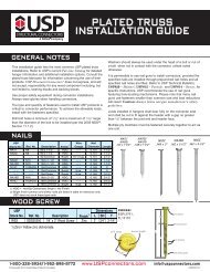
Wood Screws – WS seriesFastenersThe WS Wood Screw is a self-drilling screw used for numerous framingapplications. This screw features a reverse locking serration on the bottom ofthe screw head to help prevent over tightening against a steel plate. The <strong>USP</strong>head stamp identifies screws for easy inspection.Screw shear capacities are based on a diameter of 0.242˝ when the shear planeis on the screw shank (SH) and 0.185˝ when the shear plane is on the knurl orthreads (T). <strong>USP</strong> WS Wood Screws have a bending yield strength of 180,000psi.Materials:Finish:1/4˝ diameter Grade 5 steelSee chartInstallation:• Screws are self-drilling.• Install using a low speed clutch drill with 3/8˝ hex head driver. The washerhead should be flat to the surface and the serrations will oppose turning andrelease the clutch. Do not over-tighten the screws.• Installing the screw at an angle may introduce additional bending and tensionforces into the fastener if the screw head is not flat on the bearing surface. Careshould be given to ensure the fastener is installed perpendicular to the plane ofthe side plate.LSHTWSSerrations1/4˝ Beveled reameron 2 1 /2˝ or longerWood ScrewsCut threadsSelf drilling point© Copyright 2013 <strong>USP</strong> Structural <strong>Connectors</strong>®<strong>USP</strong> nameScrew lengthFor Attaching Multi-Ply Wood Trusses orLVL or PSL members, or floor trusses,see pages 17-19.3/8˝<strong>USP</strong>Stock No.WS15WS15-GCWS2WS25WS3WS35WS45WS6DescriptionDimensions (in)Woodto WoodFactored Shear Resistance14 10 7 310 7 3(DF-LGauge Gauge Gauge Gauge(S-P-FGauge Gauge Gauge GaugeRef. No. in mm L SH T Finish 1 Unit to DF-L) 100% 100% 100% 100% to S-P-F) 100% 100% 100% 100%SDS25112-- --SDS25200SDS25212SDS25300SDS25312SDS25412SDS256006.1 x 386.1 x 386.1 x 50.86.1 x 63.56.1 x 76.26.1 x 88.96.1 x 114.36.1 x 152.41-1/21-1/222-1/233-1/24-1/261/41/41/41/43/43/41-1/41-3/41-1/41-1/41-3/4222-1/234ZincGCZincZincZincZincZincZincLbsLbsLbsLbsLbsLbsLbsLbs-- ---- ---- --323387452543543358358423487552616680680496496561625690754825825660660724789853918997997807807103110311031103110311031-- ---- ---- --277332387480480332332387443498553618618471471526582637692763763635635691746801857890890692692900900900900900900kNkNkNkNkNkNkNkN-- ---- ---- --1.441.722.012.422.421.591.591.882.172.462.743.023.022.212.212.492.783.073.363.673.672.932.933.223.513.804.084.444.443.593.594.584.584.584.584.584.58-- ---- ---- --1.231.481.722.142.141.481.481.721.972.212.462.752.752.092.092.342.592.833.083.403.402.832.833.073.323.563.813.963.963.083.084.004.004.004.004.004.00DF-L 2,3,4,5Steel to Wood1) Zinc = Yellow zinc dichromate; GC = Gold Coat.2) Factored Resistance values determined in accordance with CSA O86-09 Section 10.11.3) Steel side plate factored resistance based on a minimum Fu = 45,000 psi.5) Loads are for 100% duration of load factors, and may be increased for other duration factors allowed per governing building code.6) Loads are for shear applications when used as described in this catalog. Please contact <strong>USP</strong> for applications and installations involving tension forces.New products or updated product information are designated in red font.Woodto Wood 14S-P-F 2,3,4,5Steel to Wood161-800-328-5934 • www.<strong>USP</strong>connectors.com
Wood Screw Applications – WS seriesJoining 2, 3, or 4 Ply Wood Trusses© Copyright 2013 <strong>USP</strong> Structural <strong>Connectors</strong>®The installation instructions and design example shown below are intended for a design professional who will beresponsible for determining the location and number of wood screws to adequately transfer all loads on the truss.Installation:• Screw spacing shall not be greater than 24˝ on centre and less than 4˝ on centre. However, the location of anyindividual screw may be adjusted up to one-half the required screw spacing to avoid lumber defects or interferencewith other hardware.• Load or hanger spacing shall not be greater than 24˝ centre-to-centre.• The last truss ply must have a minimum of 11/4˝ of screw penetration and no more than 1/8˝ gap between each ply.• Screws cannot be installed through metal truss plates unless the Truss Engineer approves predrilling.• On 2x4 members, use one row of wood screws. On 2x6 and 2x8 use two rows, and on 2x10 use three rows. Staggerall rows.• The truss bottom chord shall have lateral bracing installed as called out by the Truss Engineer to prevent anydisplacement from torsional forces.• Install screws from one sidewithout flipping the truss.• Top and bottom chordsrequire screws and in somecases the webs may requirescrews.• All lateral bracing should beattached to each truss ply.• Increase edge and enddistances if wood splittingoccurs.2 1 /2˝ Min.1 1 /2˝ Min.Start screws onface that carrieshanger on loadSpacing4˝ min. – 24˝ max.1˝ min. Recommended (Typ)Spacing4˝ min. – 24˝ max.4˝ min1 1 /2˝ Min.End ofchordFastenersDescriptionLength (in)Factored Shear Loads (100%.) 1,2,3ShearS-P-F<strong>USP</strong>PlaneDF-LStock No. Ref. No. in mm L SH T Finish Location Lbs kN Lbs kNWS3 SDS25300 3 3/4 2 Zinc SH, T 387 1.72 332 1.48WS45 SDS25412 3 Zinc SH, T 543 2.42 480 2.14WS6 SDS25600 6 4 Zinc SH, T 543 2.42 480 2.142) The Truss Engineer shall apply all applicable adjustment factors.New products or updated product information are designated in red font.3 Ply with Mixed Wood Species:Bottom Chord: 2x6 Douglas Fir-LarchTop Chord: 2x4 Spruce-Pine-FirWS45 Wood Screw Factored Resistance:(Assume shear plane across the screw shank)Douglas Fir-Larch: 543 Ibs. each at 100%Spruce-Pine-Fir: 480 lbs. each at 100%Design ExampleTruss top chordRequired Loads:Bottom Chord Load: 500 plfTop Chord Load: 60 plfBottom Chord Wood Screw Spacing:Using 2 rows of WS45 Wood Screws in 2x62 x 543/500 x# Plies= 3.26 ft.# Plies - 1Use maximum spacing of 24˝.Top Chord Wood Screw Spacing:Only 1 row of WS45 Wood Screws in 2x4 member1 x 480/60 x# Plies= 12.0 ft.# Plies - 1Use maximum spacing of 24˝.Truss bottom chordTruss spanTypical Truss Profile (profile may vary)continued on next page1-800-328-5934 • www.<strong>USP</strong>connectors.com 17<strong>USP</strong>2240-131
Wood Screw Applications – WS series continuedFastenersJoining 2, 3, or 4 Ply LVL or PSL MembersInstallation Notes:• For 2 ply members, wood screws shall be installed withthe screw heads in the loaded ply.• For 3 or 4 ply members, wood screws shall be installed inboth outer plies.• Designer shall specify all wood screws locations.• Increase edge and end distances if wood splitting occurs.• Stagger all screws installed into the opposite face.• A minimum of 2 rows of screws shall be used for allmembers with H = 5 1/2˝ and larger.Dimensions (in)Maximum Allowable Uniform LoadsMultipleMembersthat can be applied to either outside member 1,2,3,4,5,6LVL/PSL (S.G. = 0.46)Wood Screw Spacing<strong>USP</strong>Installation 2 Rows 3 Rows2 Rows 3 Rows 2 Rows 3 RowsStock No. Ref. No. Description (in) L SH T Figure 3,9,10 Lbs/ft kN/m Lbs/ft kN/m Lbs/ft kN/m Lbs/ft kN/m Lbs/ft kN/m Lbs/ft kN/m1 1695 24.74 2545 37.14 1130 16.49 1695 24.74 850 12.40 1270 18.53WS35 SDS25312 3-1/2 3/4 2-1/22 1270 18.53 1910 27.87 850 12.40 1270 18.53 635 9.27 955 13.944 1270 18.53 1910 27.87 850 12.40 1270 18.53 635 9.27 955 13.945 1130 16.49 1695 24.74 755 11.02 1130 16.49 565 8.25 850 12.40WS6 8 SDS25600 6 1-3/4 43 1455 21.23 2185 31.89 970 14.16 1455 21.23 730 10.65 1090 15.916 5100 74.43 7640 111.50 3400 49.62 5100 74.43 2550 37.21 3820 55.751) Factored Resistance values determined in accordance with CSA O86-09 Clause 10.11.4) Except for Figure 6 installation, load values neglect any contribution of screws installed to opposite side, even if they extend significantly into the loaded ply.red font.LSHTSerrations1/4˝ Beveled reameron 2 1/2˝ or longerWood ScrewsCut threadsSelf drilling point© Copyright 2013 <strong>USP</strong> Structural <strong>Connectors</strong>®Figure 1 Figure 2 Figure 3 Figure 4 Figure 5 Figure 6WS35 installedin (2) 13/4˝ PlyWS35 installedin (3) 13/4˝ PlyWS6 installedin (4) 13/4˝ PlyWS35 installedin (1) 13/4˝,(1) 31/2˝ PlyWS35 installedin (2) 13/4˝,(1) 31/2˝ PlyWS6 installedin (2) 31/2˝ PlyRecommended Row Guidelines1˝ min. Recommended (Typ)Other Stagger patterns as approved by Engineer are acceptable1 1 /2˝min18H2 1 /2˝min2 1 /2˝min1 1 /2˝minSpacing4˝ min. – 24˝ max.Spacing4˝ min. – 24˝ max.1-800-328-5934 • www.<strong>USP</strong>connectors.com4˝ minEnd of membercontinued on next page
Wood Screw Applications – WS series continued© Copyright 2013 <strong>USP</strong> Structural <strong>Connectors</strong>®Joining 2 Ply 4x2 Floor TrussesThe following information pertains to the use of the <strong>USP</strong>’s WS6 Wood Screws to fasten together a two-ply 4x2 floor trussgirder, such that the induced loads are supported by both truss plies. Screw spacing and the location of each specificscrew may vary depending on the design criteria for each application, and therefore must be determined by the truss orbuilding designer. However, in the determination of screw locations, the following criterion shall also be considered.These criterion are varying dependent upon how trusses are loaded as follows:Uniform/Distributed Load• Screws shall be installed into the top chord with a horizontalspacing between screws of not less than 4-inches on centre andnot more than 24-inches on centre.• A minimum end distance of 4-inches must be maintained. Ifnecessary, additional screws may be installed in the bottom chord.• Centre screw vertically on 11/2˝ dimension of top chord. Ifsplitting occurs, it may be necessary to pre-drill the holes inaccordance with the code.• The screws shall be installed with the headed end of the screwon the loaded truss. If either ply is “the loaded truss”, the screwsshall be divided between the two plies, with the spacing on eachside twice the minimum indicated above.• The screws shall not be installed through the metal truss plates,unless approved by the truss designer and the plates arepre-drilled, on each side to a 1/4-inch diameter. Do not drill throughthe wood.• The maximum gap between the wood members of the twotrusses shall be 1/8-inch.• The truss designer shall design the truss members with thecapacity and capability of the screws in mind, and shall meet allprovisions of the code and ANSI/TPI.• Individual screw locations may need to be adjusted to avoidconflicts with connectors, problematic wood or other framingmembers. Adjustments should follow the criteria described in thissection.Concentrated/Point LoadThe placement of fasteners for concentrated loading includes allrequirements of uniform loading with the additional followingcriteria:• Loads must occur over a vertical member, and the necessaryconcentration of screws shall be installed in the vertical member.• Additional screws may be installed on the top chord andadjacent web members if necessary.• The fasteners should be grouped as close to the concentratedload as possible, but satisfy the same minimum spacingindicated for uniform loading.• In no case shall the required group of fasteners extend beyond12-inches from the location of the concentrated load.Uniform/Distributed LoadApplied distributed loadWS6 Wood ScrewsWS6 Wood ScrewAdditionalWS6 Wood Screwif necessaryConcentrated/Point Load12˝maxApplied Concentrated LoadApplied Concentrated Load12˝maxFastenersTruss Members3 1 /2˝3 1 /2˝ 5/8˝ - 7 /8˝Factored Shear Loads (100%) 1<strong>USP</strong>DF-LS-P-FStock No. Ref. No. Lbs kN Lbs kNWS6 SDS25600 672 2.99 591 2.631) Factored Resistance values determined in accordancewith CSA O86-09 Clause 10.11.New products or updated product information aredesignated in red font.1 1 /2˝Screw DetailTyp. @ allmembersWS6 Wood Screw1-800-328-5934 • www.<strong>USP</strong>connectors.com 19<strong>USP</strong>2240-131
Lumberlok Structural Connector Screws - LL seriesFastenersThe LumberLok Structural Connector Screw is a self-drilling screw that can beused with a number of <strong>USP</strong> Structural <strong>Connectors</strong> and also for wood-to-woodapplications. The screws feature a T20 Torx® head with integral washer andgimlet point for ease of installation. The twin-lead threads drive in twice as fastas the single lead threads significantly reducing installation time. The <strong>USP</strong>head stamp identifies the screw length for easy inspection.Screw shear capacities are based on a diameter of 0.162” when the shear planeis on the screw shoulder (SH) and 0.109” when the shear plane is on thethreads (T). LumberLok Structural Connector Screws have a bending yieldstrength of 180,000 psi.T20 Torx ®headScrewlengthMaterials: Low carbon hardened steel.Finish: See chartInstallation:• Screws are self-drilling.• Install using a low speed clutch drill with T20 Torx® bit. The washer headshould be flat to the surface. Do not over-tighten the screws.• Installing the screw at an angle may introduce additional bending and tensionforces into the fastener if the screw head is not flat to the bearing surface. Careshould be given to ensure the fastener is installed perpendicular to the plane ofthe fastener hole.LL915SHL© Copyright 2013 <strong>USP</strong> Structural <strong>Connectors</strong> ®Dimensions (in.)<strong>USP</strong>Wood-to- WithdrawalShearWood-to- WithdrawalShearStock No. Ref. No. Description L SH T Finish 2 Unit Wood Capacity 18 Ga 16 Ga Wood Capacity 18 Ga 16 GaLL915LL930SD9112SD9212#9 x 1-3/8#9 x 2-7/81-3/82-7/81/41-3/81-1/81-1/2GCGCLbsLbs-- --228237288190249208265-- --196180219173226191243kNkN-- --1.011.051.280.851.110.931.18-- --0.870.800.970.771.010.851.081) Factored Resistance values determined in accordance with CSA O86-09 Section 10.11.2) GC = Gold Coat over Clear Zinc Trivalent.3) Factored shear resistance for steel-to-wood assumes a side plate tensile strength of 45 ksi.4) Withdrawal loads for steel-to-wood connections assume a side plate thickness of 1 / 4 " or less.5) Shear loads for wood-to-wood connections assume a side member thickness of 1 1 / 2 ".6) Loads are for 100% duration of load factors, and may be increased for other duration factors allowed per governing building code.New products or updated product information are designated in red font.ShearFactored Resistance (100%) ,3,4,5,6DF-LSteel-to-WoodShearS-P-FSteel-to-WoodTwin-leadthreadsSharp GimletpointLL930TBEARING PLATES – BP, HBPS, LBP, & LBPS SERIES20BP & LBP – Designed to meet code requirements for mudsill-to-foundation.HBPS & LBPS – Offers anchor bolt adjustment slots.Materials: See chartFinish: BP & HBPS – none;LBP & LBPS – G-185 galvanizingOptions: BP12, BP582, BP583, HBPS12, and HBPS58models are available in Hot-dip galvanized.To order, add HDG to end of stock number,as in BP12-HDG.Installation:• Bolt holes are sized 1⁄16˝ larger than Bolt Dia. shown in chart.Typical BearingPlate installationWBP/LBPStandardBearing PlateLPT TWHBPS/LBPSSlotted Bearing PlateL1-800-328-5934 • www.<strong>USP</strong>connectors.comDimensions (in)<strong>USP</strong>Stock No. Ref. No.PlateThickness(T)W LBoltDia.(in)LBP12-TZLBP1/2,LBP1/2Z10 Ga 9/64 2 2 1/2LBP58-TZLBP5/8,LBP5/8Z10 Ga 9/64 2 2 5/8LBPS12-TZLBPS1/2,LBPS1/2Z10 Ga 9/64 3 3 1/2LBPS58-TZLBPS5/8,LBPS5/8Z10 Ga 9/64 3 3 5/8HBPS12 BPS1/2-3 3 Ga 1/4 3 3 1/2HBPS34 BPS3/4-3 3 Ga 1/4 3 3 3/4HBPS58 BPS5/8-3 3 Ga 1/4 3 3 5/8BP12 BP1/2 7 Ga 3/16 2 2 1/2BP582 BP5/8-2 7 Ga 3/16 2 2 5/8BP583BP5/8,BP5/8-33 Ga 1/4 3 3 5/8BP343 BP3/4-3 3 Ga 1/4 3 3 3/4
Concrete & Masonry© Copyright 2013 <strong>USP</strong> Structural <strong>Connectors</strong>®®EPOXY & MECHANICALANCHORING SYSTEMS. . . . . . . . . . . . . . . PAGES 23-26• CIA-GEL 7000-C SeriesCode compliant epoxy.• CIA-GEL 7000 SeriesMasonry approved epoxy.• CIA-GEL 6000-GP SeriesGeneral purpose, quick cure epoxy.• CIA-EA SeriesEpoxy acrylate structural adhesive.• Miracle Bond ®Multi-purpose bonding and repair epoxy.• DUC SeriesDuctile Undercut Anchors.• Wedge-Bolt ® + SeriesScrew anchor.• Power-Stud HD5 SeriesExpansion anchor.Masonry Metals . . . . . . . . . . Pages 27-29• SAL SeriesSteel angle lintels.• WM SeriesWelded wire mesh.• CR SeriesConcrete reinforcing rod.• TW Series & TWTTTie Wire and Tie Wire Tying Tool.• RCD & RCTRod chairs hold reinforcing bars for proper placement during thepouring or application of concrete.• SCV & SCHSafety caps to protect against injuries from rebar.• ABS12Anchor bolt stabber for placement in wet concrete.• THR SeriesThreaded rod.• CRE24Epoxy coated rebar.• NSRNail stake secures form boards to prevent movement and bowing.CIA-GEL 7000-C CIA-GEL 7000 CIA-GEL 6000-GPCIA-EAMiracle Bond ®DUCDUCSBWedge-Bolt ® +Power-Stud HD5SALWM48CRTW TWTT RCD RCTSCVSCH CRE24 ABS12Concrete & Masonry• RP6Oversized plate to distribute forces on masonry surface.THRNSRRP6Concrete Form Ties & Wedge . . . Page 30• FT SeriesLow foundation wall tie.• WGWedge for FT tie.• RKSKwik strip tie for foundation applications.1-800-328-5934 • www.<strong>USP</strong>connectors.com21<strong>USP</strong>2240-131FTRKSWG
Concrete & MasonryAnchor Bolts. . . . . . . . . . . . . . Pages 31-33• STB & STBL Series<strong>USP</strong> anchor bolts designed for higher capacityapplications.• AB & ABP Series<strong>USP</strong> anchor bolts designed for general capacityapplications.STB/STBL AB ABPLConcrete & MasonryFoundation Anchors . . . . . . . Pages 33-35• SFA & SFJABolted mudsill anchors for retro-fit applications.• FA3Embedded mudsill and stud anchors.• ST SeriesEmbedded mudsill anchors.Laminated Beam Seats . . . . . . . . . Page 36• KGLB, KGLBT, & KHGLB SeriesSeats for beams bearing on concrete or masonry.SFA SFJA FA3 ST1-TZKGLB KGLBTST2-TZKHGLB© Copyright 2013 <strong>USP</strong> Structural <strong>Connectors</strong>®®Jack Posts . . . . . . . . . . . . . . . Pages 37-39• JP SeriesLight-duty adjustable support post.• Type 2 SeriesHeavy-duty adjustable support post for maximum loads.JP Type 2221-800-328-5934 • www.<strong>USP</strong>connectors.com
ADHESIVE ANCHORING SYSTEMSCIA-GEL 7000-C EPOXY − GEL7C SERIES© Copyright 2013 <strong>USP</strong> Structural <strong>Connectors</strong> ®CIA-GEL 7000-C Epoxy is an adhesive designed to attach anchor bolts into concrete that is, or maybecome, cracked due to cyclic loading from wind or earthquakes. It may also be used with fully groutedCMU construction. It is a low odor, solvent free, non-shrink, non-sag adhesive. The two-component(resin and hardener) epoxy is supplied in equal volume cartridges, which are combined in a 1:1ratio when dispensed through the attached mixing nozzle. Either a hand powered or air-powereddispenser may be used. The cartridges are sealed with a D-plug which opens easily on the jobsiteand allows partially used cartridges to be saved for later use. The epoxy has a two year shelf life whenstored in unopened containers at temperatures between 10ºC/50ºF and 25ºC/77ºF.Applications:• Anchors All-Thread rod and deformed rebar into concrete• Hold downs into concrete for high seismic zones• Horizontal and overhead anchoring applications (requires special inspection)CIA-GEL 7000 EPOXY − GEL7 SERIESNEWCIA-GEL 7000 Epoxy is a structural adhesive specifically designed to attach anchor bolts into fullygrouted concrete masonry units (CMU) and evaluated for seismic, sustained load, elevated temperatureand freeze-thaw suitability conditions. It can also be used to install anchor bolts into uncrackedconcrete and reinforced brick. It is a low odor, solvent free, non-shrink adhesive. The two-component(resin and hardener) epoxy is supplied in equal volume cartridges, which are combined in a 1:1 ratiowhen dispensed through the attached mixing nozzle. Either a hand powered or air-powered dispensermay be used. The cartridges are sealed with a D-plug which opens easily on the jobsite and allowspartially used cartridges to be saved for later use. The epoxy has a one year shelf life when stored inunopened containers at a temperature of 21ºC/70ºF.Applications:• Anchors All-Thread rod and deformed rebar into fully grouted CMU• Brick veneer anchoring• Crack injection of medium to wide cracks• Anchors rebar and All-Thread rod into uncracked concreteNEWAvailable in:10 oz. – GEL7C-1022 oz. – GEL7C-22Available in:10 oz. – GEL7-1022 oz. – GEL7-22Concrete & MasonryCIA-GEL 6000-GP EPOXY − GEL6GP-22CIA-GEL 6000-GP is a superior epoxy specifically designed for general purpose structural applicationsthat require quick load times and for doweling applications. It is a two-component (1:1 ratio)adhesive epoxy with 100% solids and is solvent free, moisture insensitive, non-sag and has no odor.It provides exceptional strength in anchoring and doweling applications and can be used in temperaturesbetween 1ºC/35°F and 45ºC/115°F. The epoxy has a two year shelf life when stored inunopened containers at temperatures between 4ºC/40°F and 35ºC/95°F.Applications:• Doweling applications for rebar and tie bars for full depth concrete pavement repairs• Anchoring and bracing for short term tensile load where dynamic, vibratory, wind orintermittent loads exist• Use in concrete, grout filled block and unreinforced masonry for general purposeanchoring and doweling applications• Concrete doweling road repairsNEWAvailable in:22 oz. – GEL6GP-22See Anchoring Solutions Catalog or visit www.uspconnectors.com/epoxyindex.shtml for more information1-800-328-5934 • www.<strong>USP</strong>connectors.com23<strong>USP</strong>2240-131
ADHESIVE ANCHORING SYSTEMSCIA-EA EPOXY ACRYLATE − EA SERIESConcrete & MasonryCIA-EA Adhesive Anchoring System is an epoxy acrylate specifically designed to be a high strength,fast cure structural adhesive for anchoring threaded rod and deformed rebar into uncracked concrete.It has the added advantage of being formulated to be used in colder temperatures (0°C/32°F) whilemaintaining excellent flowability. CIA-EA may also be used with fully grouted CMU and reinforcedbrick construction. It is a 2-component, 100% solids, moisture insensitive adhesive that is ideally suitedfor a wide range of applications. It is composed of a proprietary blend of solvent free epoxy acrylateresin and is backed by independent research and testing. The epoxy has a 15 month shelf lifewhen stored in unopened containers at temperatures between 5°C/41°F to 25°C/77°F.Applications:• Anchors All-Thread rod into concrete• May also be used to anchor rebar, started bars and dowels• Applications requiring fast cure times• Cold weather applications• Can be used in horizontal anchoring applications• Can be used in overhead anchoring applications (requires special inspection)NEWAvailable in:10 oz. – EA-1028 oz. – EA-28© Copyright 2013 <strong>USP</strong> Structural <strong>Connectors</strong> ®MIRACLE BOND® EPOXY − MB-9Miracle Bond® is a high strength two-component epoxy specifically designed to be a bonding agent foralmost all household materials including wood, steel, concrete, brick, stone and CMU block. It is moistureinsensitive and can also be used to fill cracks in concrete, block and stone. The epoxy has a 2 yearshelf life when stored in unopened containers in dry conditions between 4°C/40°F to 35°C/95°F.Applications:• Bonding applications for:ConcreteBrickCMU blockStoneMetalWood• Repair vertical and overhead cracks in concrete (non-structural)• Repair vertical and overhead spalls in concrete (5/8” deep & 3” diameter max)• Non-sag consistency makes this ideal for corner repairs to concrete and block walls• Repair and replace brick• Replace pool tile (no need to empty pool)• Fill holes and cracksNEWAvailable in:8.6 oz. – MB-924See Anchoring Solutions Catalog or visit www.uspconnectors.com/epoxyindex.shtml for more information1-800-328-5934 • www.<strong>USP</strong>connectors.com
Undercut Anchoring Systems - DUC Ductile Undercut AnchorsMechanical anchor expanded into a hole that has been undercut at thebottom using an undercutting drill bit creating a true bearing type anchorthat performs like a cast-in-place headed anchor. Load is transferred intothe concrete through bearing, not friction like traditional expansionanchors. Excellent performance in seismic and dynamic loadingconditions. Meets ACI 318-02 Appendix D requirements as a codeanchor, including seismic loading, tension zone, and cracked concreteprovisions.DUCUndercut Anchor© Copyright 2013 <strong>USP</strong> Structural <strong>Connectors</strong> ®Rod Materials: ASTM A36 (L Series), A193 Grade B7(H Series), or AISI 316 Stainless StudsAnchor Body Materials: ASTM A 513 Type 5, or AISI 316 StainlessInstallation:UCBUndercut Drill BitConcrete & MasonryDrill the hole toproper depthand diameterper specificationsusingrotohammerand stop drill.Clean thehole using ablow-out bulbor compressedair.Insert theundercut bitand start therotohammer.Undercutting iscomplete whenthe stoppersleeve is fullycompressed(gap closed).Clean the holeagain using ablow-out bulbor compressedair.Insert anchorinto hole. Placesetting sleeveover anchorand drive theexpansionsleeve overthe expansioncoupling.Verify that thesetting markis visible onthe threadedrod above thesleeve.Apply propertorque.lbdcdbTension and Shear Capacities for DUCAnchors in f’c > 2,500 psi concretehefho<strong>USP</strong>Stock No.DUC38-275LDUC38-275LTDUC38-400HDUC38-400HTDUC12-400LDUC12-400LTDUC12-500HDUC12-500HTDUC12-675HDUC12-675HTDUC58-450LDUC58-450LTDUC58-750HDUC58-750HTDUC58-900HDUC58-900HTDUC34-500LDUC34-500LTDUC34-1000HDUC34-1000HTRod Dia. d bExpansionCoupling Dia. d cDrilled HoleDepth of Stop Bit h oAnchorLength, l bin mm in mm in mm in mm in mm Lbs kN Lbs kN3-1/8 79.4 2-3/4 69.9 5-1/2 139.7 4650 20.69 2790 12.413/8 9.5 5/8 15.94-3/8 111.1 4 101.6 6-3/4 171.5 9690 43.10 5815 25.871/25/83/412.715.9193/411-1/81925.428.61) Factored resistance and shear capacities are for anchors installed at standard edge distance and spacing inuncracked concrete. For cracked concrete capacities, see the <strong>USP</strong> Anchoring Systems Design Guide.4-1/45-1/47589-1/25-7/810-7/8107.9133.4177.8127203.2EffectiveEmbedment h ef456-3/44-1/27-1/2114.3190.5789-3/47-3/410-3/413-5/8177.8203.2247.6196.9273.1241.3 9 228.6 12-1/4 311.2149.2276.2510101.6127171.51272548-5/8 219.1346.1UltimateTensileCapacity, N s8515 37.88 5110177401356078.9160.3228250 125.67 16950UltimateShearCapacity, V s10645813520040 89.15 1202541750 185.72 2505022.7347.3536.1975.4053.49111.431-800-328-5934 • www.<strong>USP</strong>connectors.com25<strong>USP</strong>2240-131
MECHANICAL ANCHORS - WEDGE-BOLT®+ SERIESConcrete & MasonryThe Wedge-Bolt ® + anchor is aone piece, heavy duty screwanchor with a finished hexhead. It is simple to install, easyto identify and fully removable.The Wedge-Bolt ® + has featuresand benefits that make it wellsuited for many applications.The steel threads along theanchor body tap into the holeduring installation to provide keyengagement. Suitable basematerials include normal-weightconcrete, structural sand-lightweightconcrete, concrete oversteel deck, concrete masonryand solid clay brick. The anchoris designed for structural loadingin cracked and uncrackedconcrete.NEWWedge-Bolt ® +<strong>USP</strong>Anchor<strong>USP</strong>Anchor<strong>USP</strong>UsableFinishStock No. 2Ref. No.Size (in) 1FinishStock No. 2Ref. No.Size (in) 17204SD -- -- 1/4 x 1-1/4 7282SD THD75400H 3/4 x 4 1314 SDS 1/4" x 6" 4"7206SD THD25134H 1/4 x 1-3/4 7284SD THD75500H 3/4 x 5 1318 SDS 3/8" x 8" 6"Zinc7208SD THD25214H 1/4 x 2-1/4 7286SD THD75600H 3/4 x 6 1384 HD Straight Shank 3/8" x 13" 4"Plated7210SD THD25300H 1/4 x 3 7288SD -- -- 3/4 x 8 1322 SDS 1/2" x 10" 8"7220SD THD37134H 3/8 x 1-3/4 7290SD THD75100H 3/4 x 10 1354 SDS-Max 1/2" x 13" 8"7222SD THD37212H 3/8 x 2-1/2 7726SD THD37400HMG 3/8 x 4 1394 HD Straight Shank 1/2" x 13" 11"7224SD THD37300H 3/8 x 3 7728SD THD37500HMG 3/8 x 5 1324 SDS 5/8" x 8" 6"7226SD THD37400H 3/8 x 4 7730SD THD37600HMG 3/8 x 6 1326 SDS 5/8" x 12" 10"7228SD THD37500H 3/8 x 5 7746SD THD50400HMG 1/2 x 4 1356 SDS-Max 5/8" x 13" 8"7230SD THD37600H 3/8 x 6 7748SD THD50500HMG 1/2 x 5 1396 HD Straight Shank 5/8" x 13" 11"7240SD THD50200H 1/2 x 2 7750SD THD50600HMG 1/2 x 6 1328 SDS 3/4" x 8" 6"Zinc7242SD THD50212H 1/2 x 2-1/2 7751SD THD50612HMG 1/2 x 6-1/2 1358 SDS-Max 3/4" x 13" 8"Plated7244SD THD50300H 1/2 x 3 7752SD THD50800HMG 1/2 x 87246SD THD50400H 1/2 x 4 MechanicallyTHD62500HMG,7764SD 7248SD THD50500H 1/2 x 5 GalvanizedTHDB62500HMG5/8 x 57250SD THD50600H 1/2 x 6 THD62612HMG,7766SD 7268SD THD50800H 1/2 x 6-1/2 THDB62600HMG5/8 x 67252SD THDA62300H 1/2 x 8 7768SD THDB62612HMG 5/8 x 6-1/27260SD THD62400H 5/8 x 3 THD62800HMG,7770SD 5/8 x 87262SD THD62500H 5/8 x 4 THDB62800HMG7264SD THD62600H 5/8 x 5 7786SD -- -- 3/4 x 6Wedge-Bolt ® +7266SD THD50612H 5/8 x 6 7789SD THD75812HMG 3/4 x 8-1/2 (Zinc Plated)7270SD THD62800H 5/8 x 8 7790SD THD75100HMG 3/4 x 107280SD -- -- 3/4 x 31) The anchor size includes the diameter and length of the anchor measured from under the head.2) Wedge-Bolt®+ is marked with a blue tip and must be installed with a matched tolerance Wedge-Bit.© Copyright 2013 <strong>USP</strong> Structural <strong>Connectors</strong> ®Wedge-Bitchor<strong>USP</strong>Anchor <strong>USP</strong>Usable12Ref. No.1Stock No. Description Lengthx 1-1/4 7282SD THD75400H 3/4 x 4 1314 SDS 1/4" x 6" 4"x 1-3/4 7284SD THD75500H 3/4 x 5 1318 SDS 3/8" x 8" 6"Zincx 2-1/4 7286SD THD75600H 3/4 x 6 1384 HD Straight Shank 3/8" x 13" 4"Plated4 x 3 7288SD -- -- 3/4 x 8 1322 SDS 1/2" x 10" 8"x 1-3/4 7290SD THD75100H 3/4 x 10 1354 SDS-Max 1/2" x 13" 8"x 2-1/2 7726SD THD37400HMG 3/8 x 4 1394 HD Straight Shank 1/2" x 13" 11"8 x 3 7728SD THD37500HMG 3/8 x 5 1324 SDS 5/8" x 8" 6"8 x 4 7730SD THD37600HMG 3/8 x 6 1326 SDS 5/8" x 12" 10"8 x 5 7746SD THD50400HMG 1/2 x 4 1356 SDS-Max 5/8" x 13" 8"8 x 6 7748SD THD50500HMG 1/2 x 5 1396 HD Straight Shank 5/8" x 13" 11"2 x 2 7750SD THD50600HMG 1/2 x 6 1328 SDS 3/4" x 8" 6"x 2-1/2 7751SD THD50612HMG 1/2 x 6-1/2 1358 SDS-Max 3/4" x 13" 8"2 x 3 7752SD THD50800HMG 1/2 x 82 x 4 MechanicallyTHD62500HMG,7764SDGalvanized5/8 x 52 x 67766SD 5/8 x 6SDS-Max Wedge BitSDS-Plus Wedge BitMECHANICAL ANCHORS - POWER-STUD HD5 SERIESWedge-Bolt ® +(Mechanically Galvanized)8 x 3The 7770SD Power-Stud HD5 5/8 x anchor 8 is a fullythreaded, torque-controlled, wedge expansionanchor. Suitable base materials include normal-weightconcrete and structural sand-lightweightconcrete. The anchor is manufacturedwith a hot-dip galvanized carbon steel bodyand stainless steel expansion clip. Nut andwasher are included.NEW<strong>USP</strong>Stock No. 2 Ref. No.AnchorSize (in) 1ThreadLength (in)7723HD5 WA50414MG 1/2 x 4-1/2 2-3/47724HD5 WA50512MG 1/2 x 5-1/2 3-3/47726HD5 WA50700MG 1/2 x 7 5-1/47733HD5 -- -- 5/8 x 5 37734HD5 WA62600MG 5/8 x 6 47738HD5 -- -- 5/8 x 8-1/2 6-1/21) The anchor size includes the diameter andthe overall length of the anchor.2) All anchors are packaged with nuts and washers.Power-Stud HD5261-800-328-5934 • www.<strong>USP</strong>connectors.com
Steel Angle Lintels – SAL seriesSteel Angle Lintels are used as support headers in door and windowframing. For maximum allowable spans and minimum required bearinglength check with applicable municipal, provincial or national buildingcodes.Materials: 3 gaugeFinish: Red primerW 1© Copyright 2013 <strong>USP</strong> Structural <strong>Connectors</strong> ®<strong>USP</strong>Stock No. Ref. No.SteelGauge W1Dimensions (in)W2 LSAL36 -- -- 3 3-1/2 3-1/2 36SAL42 -- -- 3 3-1/2 3-1/2 42SAL48 -- -- 3 3-1/2 3-1/2 48SAL60 -- -- 3 3-1/2 3-1/2 60SAL72 -- -- 3 3-1/2 3-1/2 72SAL91 -- -- 3 3-1/2 3-1/2 91Welded Wire Mesh – WM seriesWelded wire adds strencth and stability toconcrete foundations.Materials: 9 gauge carbon steel wireFinish: NoneW 2SALLLTypical SALinstallationConcrete & Masonry<strong>USP</strong>Stock No.Steel Dimensions (in)Ref. No. Gauge W LWM48 -- -- 9 48 96WM60 -- -- 9 60 600Concrete Reinforcing Rod – CR seriesConcrete Reinforcing Rod provides added strength and stability for anyconcrete projects.Materials: Carbon steel conforms to A615 SteelFinish: NoneWWMTypical WMinstallation<strong>USP</strong>DimensionsStock No. Ref. No. D LCR12 -- -- 10 mm CR24 -- -- 10 mm CR36 -- -- 10 mm CR48 -- -- 10 mm CR72 -- -- 10 mm CR96 -- -- 10 mm LTie Wire - TW series & TWTTTW – Tie Wire is used to secure concrete reinforcing rods in placeduring concrete forming.TWTT – Tie Wire Tying Tool.Materials: See chartFinish: TW1 – G90 galvanizingCRTypical CRinstallation<strong>USP</strong>Stock No.Ref. No.SteelGaugeLengthTW1 -- -- 18 6"TW3 -- -- 16 340'TW Typical TWTWTT Typical TWTTInstallationInstallation1-800-328-5934 • www.<strong>USP</strong>connectors.com27<strong>USP</strong>2240-131
Rod Chairs – RCD & RCTRod chairs hold reinforcing bars for proper placementduring the pouring or application of concrete.Materials: Welded WireFinish: NoneRCDTypical RCDinstallationConcrete & Masonry<strong>USP</strong>Stock No.Ref. No.DescriptionDimensions(in)RCD -- -- Double Rod Chair 4 x 5 x 8-1/4RCT -- -- Triple Rod Chair 3-1/2 x 4 x 12Safety Caps – SCV & SCH seriesBright orange safety caps protect against injuries from vertical rebar.RCTTypical RCTinstallation© Copyright 2013 <strong>USP</strong> Structural <strong>Connectors</strong> ®Materials: Composite PlasticFinish: NoneSCVTypical SCVinstallation<strong>USP</strong>Stock No. Ref. No. Description Dimensions (in)SCH -- -- Horizontal Safety Cap 2-3/8 x 2-1/2 x 2-1/2SCV -- -- Vertical Safety Cap 3-1/4 x 3-3/4 x 3-3/4Anchor Bolt Stabber (Bolt Rite) – ABS12SCHTypical SCHinstallationFor accurate placement of 1/2˝ (12.7 mm) anchor bolts in wet concrete. Theoutstanding legs are different lengths, with the shorter leg centering the anchorbolt in a 2 x 4 sill plate and the longer leg centering the anchor bolt in a 2 x 6sill plate.Materials: Composite PlasticFinish: See chartPatents: PendingInstallation:• Slide ABS over anchor bolt and screw on cap.• Place bolt in wet concrete using guides for proper edge distance.<strong>USP</strong>Bolt Dia.Stock No. 1Ref. No. (in) ColorABS12 -- -- 1/2 orange1) Anchor bolt caps are included with product.ABS12Typical ABS12installation281-800-328-5934 • www.<strong>USP</strong>connectors.com
Threaded Rods – THR series<strong>USP</strong> has added longer length THR’s to support the new deck orientedcode requirements for mechanically reinforced railing post and deck tohouse ledger board attachments.Materials: ASTM A 36 Steel, also conforms to ASTM F 1554 Grade 36Finish: Hot-dip galvanizedL© Copyright 2013 <strong>USP</strong> Structural <strong>Connectors</strong> ®Installation:• Install into wet concrete or drill minimum 1 ⁄16" oversized hole and securewith anchor epoxy.• Nuts and washers are included.<strong>USP</strong>Stock No. Ref. No.Bolt Dia.(in)L(in)THR125-HDG RFB#4X5HDG 1/2 5THR126-HDG RFB#4X6HDG 1/2 6THR128-HDG RFB#4X8HDG 1/2 8THR1218-HDG -- -- 1/2 18THR1224-HDG -- -- 1/2 24THR1236-HDG -- -- 1/2 36THR585-HDG RFB#5X5HDG 5/8 5THR588-HDG RFB#5X8HDG 5/8 8THR5812-HDG RFB#5X12HDG 5/8 12THR5816-HDG RFB#5X16HDG 5/8 16New products or updated productinformation are designated in red font.NEWSIZESEpoxy Coated Rebar – CRE24THR½" THRThreadedRodTypical THRinstallationDTB-TZPage 195Typical THRDeck to ledger installationConcrete & MasonryTwo-foot epoxy coated rebar provides maximum protectionagainst corrosion.Materials: A615 SteelFinish: Epoxy Dipped<strong>USP</strong>DimensionsStock No. Ref. No. Dia LCRE24 -- -- 10 mm 24"Round Nail Stake – NSRNail stakes are used to secure form boards to prevent movement andbowing.Materials: SteelFinish: Black PrimerInstallation:• Fastener holes will accommodate up to a 16d duplex nail.<strong>USP</strong>Dimensions (in)Stock No. Ref. No. Dia LNSR -- -- 3/4 18Retro Plate – RP6Uses heavy gauge HRPO steel and a large surfacearea to distribute seismic forces on masonry exteriors.LCRE24NSRTypical CRE24installationTypical NSRinstallationMaterials: 3/8˝ plateFinish: <strong>USP</strong> primerOptions: RP6 is available in Hot-dipgalvanized. To order add HDG tostock number, as in RP6-HDG.6˝3˝3/4˝ dia.threaded rodInstallation:• Install with a 3/4˝ diameter steel threaded rod.<strong>USP</strong>Stock No. Ref. No.RP6 RP63˝6˝RP6Typical RP6installation1-800-328-5934 • www.<strong>USP</strong>connectors.com29<strong>USP</strong>2240-131
Concrete Form Ties & Wedge – FT series & WGFT – Connect 1x and 2x nominal form lumber in low foundationwalls up to 4 feet high.11/16˝WG – V-shaped wedge assures rigidityand consistent form spacing.Materials: FT – 18 gauge, WG – 14 gaugeFinish: G90 galvanizing3 5 /8˝Concrete & MasonryInstallation:• Use the Spacing Guide chart to determine spacing betweenFT units. Each level in chart assumes 12˝ form boards. Wallthickness from 6˝ to 12˝.• Install with “V” facing up.• Use (2) WG wedges for each tie. Insert wedge into inside slotsfor 1x nominal forms and outside slots for 2x nominal forms.• No walers or stiff-backs are used.• Vertical ties to keep forms from separating are not included.• Form deflection may be substantial. Check deflection, if it iscritical, and move ties to compensate.• Forming lumber is assumed to have fb of 1,000 psi.• Not recommended for pours greater than 4 feet in height.3/16˝WG Wedgemust orderseparatelyLFTWTypical FT/WGinstallation© Copyright 2013 <strong>USP</strong> Structural <strong>Connectors</strong> ®Spacing Guide chart<strong>USP</strong>SteelDimensions (in) WedgeFooting WidthStock No. Ref. No. Gauge W L Qty Type or Wall ThicknessFT6 WT6 18 5/8 10-5/8 2 WG 6FT8 WT8 18 5/8 12-5/8 2 WG 8FT10 WT10 18 5/8 14-5/8 2 WG 10FT12 WT12 18 5/8 16-5/8 2 WG 12WG W1 14 11/16 3-5/8 -- -- -- -- -- --Concrete Level 1 Level 2 Level 3 Level 4Lift Height 1x 2x 1x 2x 1x 2x 1x 2x -- -- -- -- -- -- -- -- -- -- -- -- -- -- -- -- -- -- -- -- -- -- -- -- Kwik Strip Ties – RKS200For foundation applications where rental forms areused. Ease of form wall erection and removal makesthis system very practical and economical. Use KwikStrip Ties to hold form walls parallel, to prevent bulgingand to prevent them from collapsing while concrete isbeing poured. 2 x 4 studding is not required for formwork.Materials: 18 gaugeFinish: G90 galvanizing<strong>USP</strong>Steel Dimensions Footing Width orStockRef. No. Gauge W L Wall TicknessNo.RKS200 -- -- 18 3/4 12-1/8 approximates 8"RKSWaterbarinstalledStake every2 feet1 x 3 cleatevery 2 feetTypical RKSinstallationKwik Strip Tiesinstalled301-800-328-5934 • www.<strong>USP</strong>connectors.com
Anchor Bolts – STB & STBL seriesEmbossed ends provide guides for embedment angle and depth. An embedment line isembossed on the shaft for easy installation. Features rolled threads for high tensile strength.STB – For monolithic slabs and concrete stem walls.STBL – Designed for use with 3x sill plates. Excellent choice foruse with taller holdown washers like those in the PHD/PHDAseries.© Copyright 2013 <strong>USP</strong> Structural <strong>Connectors</strong> ®Materials: ASTM F 1554 Grade 36Finish: NoneOptions: STB16, STB20, STB24, STB28, STB34,STBL24, and STBL28 models are available inHot-dip galvanized. To order, add HDG to end ofstock number, as in STB34-HDG.Codes: Load values are derived from data submitted tovarious North American building codeevaluators.Installation:• Select appropriate STB or STBL Anchor Bolt.• Use normal weight concrete with minimum compressive strength of 2,500 psi.• Minimum centre-to-centre spacing between bolts is 3(E) for anchors actingsimultaneously in tension.• Match embedment depth with embedment line on the STB or STBL shaft.• The STB or STBL does not need to be tied to the rebar.• Nuts and washers are not included.• Use <strong>USP</strong>’s ABS12 anchor bolt stabber to hold anchor bolt in place during installation.Typical STB AnchorBolt installation(No. 4 Rebar in Breakout Zone,Min. 1-3/4” Edge Distance)Concrete & MasonryMonolithic or Stem Wall Foundations – Prior to pour, install the STB or STBL in an uprightposition and at a 45° angle to the wall. Install one horizontal #4 rebar at a depth of 4˝ (minimum).(See illustrations.)Concrete Block Applications – Prior to cell pour, install the STB or STBL in an uprightposition and at a 45° angle to the wall. (See illustrations.) Use the embossed angle guideon the end of the STB or STBL shaft as a guide. Install one horizontal #4 rebar at a depthof 4˝ and one vertical #4 rebar maximum 48˝ o.c. spacing. Fill all cells with concrete havinga minimum 2,000 psi compressive strength.STB Anchor BoltInstallation – AlongContinuous Stem Wall(No.4 Rebar Min Length = 4xl e ,Min. 1-3/4" Edge Distance)STB Anchor BoltInstallation – Cornerof Stem Wall(Min. 12" Return Stem Wall,Min. 5" End Distance)STB Anchor BoltInstallation – End ofStem Wall(Min. 5" End Distance, andNo.4 Rebar Min Length)STB Anchor Bolt(Identification on bolt head,minimum anchor embedment, l e )continued on next page1-800-328-5934 • www.<strong>USP</strong>connectors.com31<strong>USP</strong>2240-131
Anchor Bolts – STB & STBL series continuedConcrete & MasonryAnchor Bolt Selection table2x, 3x, (2) 2xSill Plates 1<strong>USP</strong>Stock No.Mono PourPHD2ATDX2-TZLTS20BSTB16HTT45STBL16HTT4HTT16PHD4ASTB20HTT45STBL20HTT45STB24HTT5STBL24PHD8UPHD8STB28TD7STBL28TD9TD12* Recommend installation ofwasher under nut of anchor bolt.1) STBL model are recommendedfor use with PHD and UPHD8holdowns on (2) 2x and 3xsill plates.Typical STB/STBLconcrete block installationCornerinstallationNon-CornerinstallationCornerinstallationPlan view of STB/STBLplacement in concrete stemwall0˚Outside edgeof concrete© Copyright 2013 <strong>USP</strong> Structural <strong>Connectors</strong> ®<strong>USP</strong>Stock No.STB16STB20STB24STB28STB34STB36STBL16STBL20STBL24STBL28Dimensions (in)StemwallMin.Seismic I e F a S a (0.2) < 0.35 Wind I e F a S a (0.2) < 0.35 Seismic I e F a S a Ref. No. Width Dia. L H Embed. (E) Unit Midwall Corner End Wall Midwall Corner End Wall Midwall Corner End WallSSTB16SSTB20SSTB24SSTB28SSTB34SSTB36SSTBL16SSTBL20SSTBL24SSTBL2866688866685/85/85/87/87/87/85/85/85/87/817-13/1621-13/1625-13/1631363819-9/1623-9/1627-9/1632-3/45555686-3/46-3/46-3/46-3/412-13/1616-13/1620-13/1626303012-13/1616-13/1620-13/1626LbsLbsLbsLbsLbsLbsLbsLbsLbsLbs592071708385141401598015980592071708385141405920663582801328514735147355920663582801328559206635828013285143501435059206635828013285677081859585145751822518225677081859585145756770677089101457516840168406770677089101457567706770891014575150501505067706770891014575493559706985107101332013320493559706985107104935497565451071012280122804935497565451071049354975654510710110601106049354975654510710kNkNkNkNkNkNkNkNkNkN26.3331.9037.3062.9071.0971.0926.3331.9037.3062.9026.3329.5236.8359.1065.5565.5526.3329.5236.8359.1026.3329.5236.8359.1063.8363.8326.3329.5236.8359.1030.1236.4142.6464.8481.0781.0730.1236.4142.6464.8430.1230.1239.6464.8474.9174.9130.1230.1239.6464.8430.1230.1239.6464.8466.9566.9530.1230.1239.6464.8421.9526.5631.0747.6459.2559.2521.9526.5631.0747.6421.9522.1329.1147.6454.6354.6321.9522.1329.1147.6421.9522.1329.1147.6449.2049.2021.9522.1329.1147.641) Loads may not be increased for short term loading.2) Minimum center to center spacing between bolts is 3(E) for anchors acting in tension simultaneously.6) Connection is limited by lowest of bolt or holdown capacity.New products or updated product information are designated in red font.Factored Tensile Resistance 1,2321-800-328-5934 • www.<strong>USP</strong>connectors.com
Anchor Bolts – AB & ABP seriesAnchor Bolts are used to secure wood plates to foundation walls. Washers areavailable in various package combinations.© Copyright 2013 <strong>USP</strong> Structural <strong>Connectors</strong> ®Materials: Bolt: ASTM F 844, Nut: ASTM A 563, Washers: ASTM F 844Finish: AB126-HDG, AB128-HDG, AB1212-HDG, AB5812-HDG –Hot-dip galvanized; All others – noneInstallation:• Select appropriate AB or ABP Anchor Bolt.• Use concrete with minimum compressive strength of2,000 psi at 28 days• Nuts and standard washers are included.• Anchor bolts intended for use to satisfy codeprescribed anchoring of mudsill plates, and shall beinstalled as defined in the code.• Factored resistance shall be derived in accordancewith the code.<strong>USP</strong>Stock No. Ref. No.BoltDia. (in)L(in)AB126-HDG -- -- 1/2 6AB128-HDG -- -- 1/2 8AB1212-HDG -- -- 1/2 12AB5812-HDG -- -- 5/8 12AB6NW -- -- 1/2 6AB8NW -- -- 1/2 8ABP6NW -- -- 1/2 6ABP8NW -- -- 1/2 8LABPTypical ABinstallationABLConcrete & MasonryFoundation Anchors – SFA & SFJA seriesSFA – Mudsill anchors for retrofit applications. Features aslotted bend line for easy field adjustment when foundation wallsare slanted.SFJA – Ties floor joists directly to foundations with bolt fastening.Materials: 12 gaugeFinish: G90 galvanizing7˝F1Installation:• Use all specified fasteners. See <strong>Product</strong> Notes, page10.• A design professional must specify anchor bolt type, length,and embedment. Anchor bolts are laterally loaded. Followinstallation instructions for epoxy adhesive.• Factored resistance assume a minimum concrete compressivestrength of 2,000 psi.8˝SFA86˝Typical SFA installationFastener ScheduleFactored Resistance 1AnchorFramingDF-LS-P-F<strong>USP</strong>SteelBoltsNails 2,4 Bolts 3 F1 Uplift F1 UpliftStock No. Ref. No. Gauge Qty Dia. Qty Type Qty Dia. 115% 115% 115% 115%SFJA FJA 12 1 5/8 -- -- -- -- 2 5/8 -- -- 1620 -- -- 1360SFA8 -- -- 12 2 1/2 7 10d x 1-1/2 -- -- -- -- 1085 -- -- 915 -- --1) The 115% values are short-term loads such as wind and earthquake.2) Minimum nail embedment shall be 8 nail diameters (typ).3) Bolts shall conform to ASTM A 307 or better.4) NAILS: red font.Uplift1 1 /2˝6˝6 1 /2˝Typical SFJAinstallation1 1 /2˝SFJA1-800-328-5934 • www.<strong>USP</strong>connectors.com33<strong>USP</strong>2240-131
Foundation Anchors – FA3 seriesConcrete & MasonryFor installation into concrete slabs. The FA3 features a split flange for nailingto both mudsill and stud for greater framing versatility.Materials: 16 gaugeFinish: G90 galvanizingOptions: FA3 is available in Triple Zinc.To order, add TZ to end of stock number,as in FA3-TZ.Codes: Load values are derived from data submitted tovarious North American building codeevaluators.Installation:• Use all specified fasteners. See <strong>Product</strong> Notes, page 10.• Use a minimum of two anchors per mudsill. An anchor should always bewithin 12˝ of the end of each mudsill section.• Do not rely on these anchors to secure concrete sections together betweencold joints.• Insert into wet concrete (minimum strength of 2,000 psi). Place mudsill afterconcrete cures. Secure flanges to sill (and stud, if applicable), bending flangesas needed to achieve a tight fit. Fasten as directed in chart.1 1 /2˝4 5 /8˝F25 3 /4˝FA3F1Embossed linesprovide guide formatching to edgeof form board1˝UpliftTypical FA3 installationin concrete© Copyright 2013 <strong>USP</strong> Structural <strong>Connectors</strong> ®FA3 Form boardinstallationAlternate FA3installationTypical FA3 installationto mudsill and studPlateSize2 x4or2 x 62 x4or2 x 6Dimensions (in)Fastener Schedule 1,9 DF-L Factored Resistance 2,3,5,6,7S-P-F Factored Resistance 2,3,5,6,7Sill PlateStud Min Wind and SDC A & B SDC C-F Wind and SDC A & B SDC C-FStemwallSide Top Uplift F1 F2 Uplift F1 F2 Uplift F1 F2 Uplift F1 F2<strong>USP</strong> Ref. SteelThicknessStock No No. Ga. W L I E D Qty Qty Type Qty Type (in.) Unit 115% 115% 115% 115% 115% 115% 115% 115% 115% 115% 115% 115%Uncracked Concrete 8FA3Lbs 1045 645 760 1045 645 760 900 555 655 900 555 655 1010 622 4 10d x 1-1/2 -- -- -- -- 6Mudsill Only MASkN 4.65 2.87 3.38 4.65 2.87 3.38 4.00 2.47 2.91 4.00 2.47 2.9116 1-1/2 4-5/8 4 1FA3Lbs 780 635 480 780 635 480 670 545 415 670 545 415 755 612 2 10d x 1-1/2 2 10d x 1-1/2 6Mudsill & StudkN 3.47 2.82 2.14 3.47 2.82 2.14 2.98 2.42 1.85 2.98 2.42 1.85Cracked Concrete 8FA3Lbs 1020 565 760 875 485 670 875 485 655 755 415 575 985 542 4 10d x 1-1/2 -- -- -- -- 6Mudsill Only MASkN 4.54 2.51 3.38 3.89 2.16 2.98 3.89 2.16 2.91 3.36 1.85 2.5616 1-1/2 4-5/8 4 1FA3Lbs 780 565 480 780 485 480 670 485 415 670 415 415 755 542 2 10d x 1-1/2 2 10d x 1-1/2 6Mudsill & StudkN 3.47 2.51 2.14 3.47 2.16 2.14 2.98 2.16 1.85 2.98 1.85 1.851) Predrilled holes are not required.2) Factored resistances have been increased 15% for short-term loads such as wind and earthquake; no further increased is allowed.3) FA3 capacities are based on using a single-ply 2x sill plate.4) Minimum distance of 1.5 x I E ( 6 inches) is required to obtain the listed capacity.5) Minimum anchor spacing for full capacity is 2 x l E . For spacing less than that reduce capacity proportionally.6) Factored resistances are based on lumber with a specific gravity of 0.49 and a moisture content of 19% or less.7) Uplift deformation based on wood connection strength.8) Minimum concrete strength f'c = 2500 psi9) Minimum nail embedment shall be 8 nail diameters (typ).10) NAILS:New products or updated product information are designated in red font.341-800-328-5934 • www.<strong>USP</strong>connectors.com
Foundation Anchors – ST seriesST1-TZ – For installation into concrete slab or poured stemwalls.The ST1-TZ features a prebent base flange to assure properanchoring into concrete.ST2-TZ – For installation into concrete slab, poured stemwalls orconcrete/masonry. The ST2-TZ features a prebent base flange to assureproper anchoring into concrete. Do not use in red clay brick.Min. embed8 1/2" E© Copyright 2013 <strong>USP</strong> Structural <strong>Connectors</strong> ®Materials: 18 gaugeFinish: G-185 galvanizingCodes: Load values are derived from data submitted tovarious North American building code evaluators.Installation:• Use all specified fasteners. See <strong>Product</strong> Notes, page 10.• Use a minimum of two anchors per mudsill. An anchor should always bewithin 12˝ of the end of each mudsill section.• Do not rely on these anchors to secure concrete sections together betweencold joints.• Spread sill flanges to mudsill width prior to insertion into wet concrete(minimum strength of 2,000 psi or 13.8 MPa). Alternate installation ispossible by inserting unbent flanges through 3/4˝ center hole predrilled inmudsill. Foundation anchors may also be attached to mudsill and theninserted into wet concrete. When installing ST2-TZ into concrete block, fill cellswith grout with a minimum strength of 2,000 psi or 13.8 MPa. Concrete blockedges may need to be beveled to facilitate installation.• ST2-TZ in masonry construction shall be installed in the core of the block andgrouted with concrete grout designed for that purpose. In no case, shall theybe installed in a mortar joint.TypicalST1-TZinstallationin concreteUpliftF 1F 2AlternateST1-TZinstallation with3/4˝center holeDrill 3 ⁄4" dia.holeDrill 3 ⁄4" dia.holeConcrete & MasonrySpread sill flanges to sillwidth prior to insertioninto wet concrete10˝18˝DO NOT installST1-TZ and ST2-TZwithout pre-bendingsill flanges in “Y”configurationST1-TZST2-TZAlternateST2-TZinstallation with3/4˝ center holein mudsillPlateSize2 x 4 - 6<strong>USP</strong>Stock No.ST1-TZST2-TZFastener Schedule 2,3Min.Factored Resistance (115%) 1Steel Mudsill Top Mudsill Side Embed. (in)DF-LS-P-FRef. No. Gauge Qty Type Qty Type(E)Unit F1 F2 Uplift F1 F2 UpliftMAB15,Lbs 979 1134 1310 839 972 112318 4 8d x 1-1/2 HDG 4 8d x 1-1/2 HDG MAB15ZkN 4.36 5.04 5.83 3.73 4.32 4.99MAB23,Lbs 979 1134 1310 839 972 112318 4 8d x 1-1/2 HDG 4 8d x 1-1/2 HDG MAB23ZkN 4.36 5.04 5.83 3.73 4.32 4.991) Factored resistances have been increased 15% for short-term loads such as wind and earthquake; no further increase is allowed.For standard term loads divide the values by 1.15.2) Minimum nail embedment shall be 8 nail diameters (typ).3) NAILS red font.1-800-328-5934 • www.<strong>USP</strong>connectors.com35<strong>USP</strong>2240-131
Laminated Beam Seats – KGLB, KGLBT, & KHGLB seriesConcrete & MasonryKGLB – Single bolt, bearing only.KGLBT – Double bolt with Structural Tee provides uplift and horizontal resistance.KHGLB – Double bolt design provides uplift and horizontal resistance.Materials: Flanges – 1/4˝ steelBearing Plate – See chartAnchor dowels – 3⁄4˝ x 12˝ rebarFinish: <strong>USP</strong> primerOptions: Consult <strong>USP</strong> for non-catalogue variations.Codes: Load values are derived from datasubmitted to various North Americanbuilding code evaluators.Installation:• Use all specified fasteners. See <strong>Product</strong>Notes, page 10.• Bolt holes shall be a minimum of 1⁄ 32˝ to amaximum of 1⁄ 16˝ larger than the bolt diameter.• Concrete or masonry walls must be checkedby a design professional for adequacy to resistlateral or uplift loads transferred from the beamseat anchor.<strong>USP</strong>StockNo.Dimensions (in) Bolt Schedule Factored Bearing Resistance 1,4,5Masonry @ 375 psi 2 Concrete 3Dia.Ref. No. W L T D Qty(in)Lbs kN Lbs kNKGLB5A GLB5A 5-1/4 7 1/4 5 1 5/8 16980 75.53 16980 75.53KGLB5B GLB5B 5-1/4 7 3/8 6 1 5/8 20370 90.61 20370 90.61KGLB5C GLB5C 5-1/4 7 3/8 7 1 5/8 23765 105.72 23765 105.72KGLB5D GLB5D 5-1/4 7 3/8 8 1 5/8 27160 120.82 27160 120.82KGLB7A GLB7A 6-7/8 9 1/4 5 1 3/4 22355 99.44 22355 99.44KGLB7B GLB7B 6-7/8 9 3/8 6 1 3/4 26825 119.33 26825 119.33KGLB7C GLB7C 6-7/8 9 3/8 7 1 3/4 31300 139.23 31300 139.23KGLB7D GLB7D 6-7/8 9 3/8 8 1 3/4 35770 159.12 35770 159.121) Beams must fully bear on plates.2) Factored bearing resistances are based on the bearing value listed times the bearing area equal to W x D. (Note that fullbearing plate area is not used.) Factored bearing resistances shall be reduced where limited by wood bearing on the plate.3) Factored bearing resistances on concrete are based on factored wood bearing stress perpendicular to the grain of 460 psiand actual beam width times beam bearing length.4) Designer shall specify minimum edge and spacing requirements in masonry or concrete structure.5) Concrete or masonry support structure is assumed adequate to support loads listed.<strong>USP</strong>Stock No.KHGLBAKHGLBBKHGLBCKHGLBDKGLBT512KGLBT612KGLBT516KGLBT616KGLBT520KGLBT620TL3˝3 1 /2˝KGLBWD12˝Bearing PlateConcrete pilasterRebar welded tobearing plateDimensions (in)BoltFactored Bearing Resistance 1,5ScheduleMasonry On Concrete with Beam Width 1 F2 3,4 Min. 3-1/8RangeDia.@Beam Width (W)Ref. No. W D L T Qty (in) Unit 375 psi 5-1/8 6-3/4 8-3/4 10-3/4 100% Uplift 115% 3HGLBAHGLBBHGLBCHGLBDGLBT512GLBT612GLBT516GLBT616GLBT520GLBT6203-1/4 to 93-1/4 to 93-1/4 to 93-1/4 to 93-1/4 to 113-1/4 to 113-1/4 to 153-1/4 to 153-1/4 to 193-1/4 to 1956785-1/26-1/25-1/26-1/25-1/26-1/2101010101212161620203/83/83/83/81/33/81/33/81/33/822222222223/43/43/43/43/43/43/43/43/43/4LbsLbsLbsLbsLbsLbsLbsLbsLbsLbs27000324003780043200356404212039170462903917046290169802037023765271601867022070186702207018670220702235526825313003577024595290652459529065245952906528980347754057046370318803768031880376803188037680-- ---- ---- ---- --39170462903917046290391704629094459445944594459445944594459445944594454045404540454045404540454045404540454045kNkNkNkNkNkNkNkNkNkN120.11144.13168.15192.17158.54187.37174.24205.92174.24205.9275.5390.61105.72120.8283.0598.1883.0598.1883.0598.1899.44119.33139.23159.12109.41129.29109.41129.29109.41129.29128.91154.69180.47206.27141.81167.62141.81167.62141.81167.62-- ---- ---- ---- --174.24205.92174.24205.92174.24205.9242.0242.0242.0242.0242.0242.0242.0242.0242.0242.0217.9917.9917.9917.9917.9917.9917.9917.9917.9917.991) Beams must fully bear on plates.2) Factored bearing resistances on concrete are based on factored bearing stress perpendicular to the grain of 460 psi andactual beam width times beam bearing length.3) The 115% values are short-term loads such as wind and earthquake and are based on bolt in wood values only.Factored resistances assume concrete or masonry structure is adequate to resist loads in those directions.4) Factored resistances must be be reduced if the allowable lateral load (F2) for masonry or concrete column governs.5) Designer shall specify minimum edge and spacing requirements in masonry or concrete structure.1/2˝ Min.clearanceUpliftF2Typical KGLB installationDL3˝L3 1 /2˝1 1 /2˝3˝2 1 /2˝1 1 /2˝WStructuralteeKGLBTW2 1 /2˝KHGLB1 1 /4˝T1 1 /4˝DT3˝4˝ 12˝3˝© Copyright 2013 <strong>USP</strong> Structural <strong>Connectors</strong> ®361-800-328-5934 • www.<strong>USP</strong>connectors.com
Adjustable Support Posts – JP seriesAdjustable Support Posts may be used to support carport roofs and beamscarrying loads not more than two wood frame floors, where the length of joistscarried by such beams does not exceed 16’ and a live load on any floor does notexceed 50 lbs/ft 2 .© Copyright 2013 <strong>USP</strong> Structural <strong>Connectors</strong> ®Materials: 3 gauge steel plates (3.5˝ x 6˝);12 gauge outer tube (2 3⁄4˝ O.D);11 gauge inner tube (2 1⁄2˝ O.D.)Finish: RSC Red Primer PaintCodes: JP108: CCMC 09199-LConform to NBC 2010, Article 9.17.3.4.(1) and toCAN/CGSB-7.2-94.Installation:• Elevate top tubing to approximate height and insert locking pin. Rotate jack screwto desired height, then fasten top plate in position. Ensure top and bottom plates areproperly fastened to supported beam members and properly aligned to thesupported base footing. Always ensure product is installed 90º to beam and footing.<strong>USP</strong>SteelAdjustable Height Allowable Load 1,2 Factored Resistance 1,2Stock No. Ref. No. Gauge in mm Lbs kN Lbs kNJP24 -- -- 3 17 - 24 432 - 610 8555 38.06 12319 54.80JP60 -- -- 3 36 - 60 914 - 1524 8555 38.06 12319 54.80JP96 -- -- 3 60 - 96 1524 - 2438 8555 38.06 12319 54.80JP108 -- -- 3 72 - 108 1829 - 2743 8177 36.37 11775 52.381) The loads given above the established in accordance with CAN/CGSB-7-2 for allowableload design. The factored resistances given above are for Limit States Design inaccordance with the 1995 National Building Code of Canada.2) The bearing resistance of the supported beam should be checked by the building designerusing the appropriate CSA standard.JPConcrete & MasonryReplacement Parts forAdjustable Support Posts<strong>USP</strong>Stock No.Qty/PackageDescriptionJPCP Setting Pin 1JPSN Screw & Nut Assembly 1JPSP 6" x 7" Steel Plate 15JPSSN Screw & Nut Assembly 1JPTP Top Plate 1Typical JPinstallationJPSPJPSNJPSSNJPTPJPCP1-800-328-5934 • www.<strong>USP</strong>connectors.com37<strong>USP</strong>2240-131
Adjustable Support Posts – Type 2 seriesConcrete & MasonryMeets or exceeds CCMC requirements for a Type 2 Adjustable Steel Column andmay be used to support carport roofs and beams carrying not more than two woodframefloors where the length of the joists carried by such beams does not exceed16 feet and the live load on any floor does not exceed 50 lbs/ft 2 . May also be usedon projects exceeding the prescriptive requirements where a professional engineeris directly involved and the factored resistance requirements are met.Materials: Top & Bottom Plates (4 1⁄2˝ x 6˝) – 3 gauge;T2JPLD Light-Duty Tube (2 1⁄2˝ x 2 1⁄2˝) – 11 gauge;T2JPHD Heavy-Duty Tube (3˝ x 3˝) – 8 gaugeFinish: Tube – Powder Coated Red PaintPlates – Grey Primer PaintCodes: Conforms to CAN/CGSB-7.2-94.Installation:• Elevate supported beam to the proper height. Turn threaded collar to extendpost to the desired length. Ensure that the top and bottom plates are properlyfastened to the supported beam and aligned properly with the supportingfoundation. Always ensure product is installed 90° to the beam and footing.Light Duty Type 2 Column<strong>USP</strong>Adjustable Height Extended Length Allowable Load (100%) 1,3 Factored Resistance (100%) 2,3Stock No in mm in mm kN Lbs kg kN Lbs kgT2JPLD84 80 - 84 2032 - 2134 84 2134 75.2 16900 7665 115.8 26000 11813T2JPLD88 84 - 88 2134 - 2235 88 2235 68.9 15500 7030 108.1 24300 11020T2JPLD90 86 - 90 2184 - 2286 90 2286 66.7 15000 6805 105.4 23700 10750T2JPLD96 92 - 96 2337 - 2438 96 2438 60.5 13600 6170 97.4 21800 9936T2JPLD102 98 - 102 2489 - 2591 102 2591 56.9 12800 5805 89.2 20050 9095T2JPLD108 104 - 108 2642 - 2743 108 2743 54.3 12200 5535 82.2 18400 8385T2JPLD120 116 - 120 2946 - 3048 120 3048 48.5 10900 4945 69.8 15600 7119NEW &IMPROVEDDESIGN9/16" holefor heightadjustmentType 2 Post© Copyright 2013 <strong>USP</strong> Structural <strong>Connectors</strong> ®Heavy Duty Type 2 Column<strong>USP</strong>Adjustable Height Extended Length Allowable Load (100%) 1,3 Factored Resistance (100%) 2,3Stock No in mm in mm kN Lbs kg kN Lbs kgT2JPHD84 80 - 84 2032 - 2134 84 2134 176.1 39600 17960 222.5 49900 22687T2JPHD88 84 - 88 2134 - 2235 88 2235 162.8 36600 16600 210.4 47300 21455T2JPHD90 86 - 90 2184 - 2286 90 2286 157.9 35500 16100 206.4 46400 21045T2JPHD96 92 - 96 2337 - 2438 96 2438 142.8 32100 14560 193.5 43400 19728T2JPHD102 98 - 102 2489 - 2591 102 2591 133.4 30000 13610 179.3 40300 18280T2JPHD108 104 - 108 2642 - 2743 108 2743 125.9 28300 12835 167.7 37600 17104T2JPHD120 116 - 120 2946 - 3048 120 3048 119.2 26800 12155 145.5 32700 148381) The Allowable Load values have been determined thru testing standards prescribed inthe National Research Council Evaluation Directive for Adjustable Steel Columns using asafety factor of 2.25.3) The bearing resistance of the supported beam should be checked by the building designerusing the appropriated CSA standard.New products or updated product information are designated in red font.AdjustmentAssemblyHEAVY DUTYADJUSTMENT ASSEMBLYFOR MAXIMUM LOADSMODULAR DESIGN FORGREATEST JOB SITEFLEXIBILITYSquare TubeDesign38SQUARE POST FOR EASYAND ACCURATE CUT DOWNUSE REBAR/ROD THROUGH9/16” HOLE FOR HEIGHTADJUSTMENT1-800-328-5934 • www.<strong>USP</strong>connectors.comUniversal PlateType 2 Heavy- Duty SupportPost Accessories on next page
Type 2 Top Plates – T2TP Series© Copyright 2013 <strong>USP</strong> Structural <strong>Connectors</strong> ®Type 2 Heavy-Duty Top Plates are compatible with Type 2 Adjustable SupportPosts and provide additional bearing for Structural Composite Lumber (SCL)beams and dimensional lumber. They are easily placed and aligned on top of thestandard steel column top plate supplied with each <strong>USP</strong> Type 2 column and canbe quickly fastened to the supported beam.T2TP527 – 5-1/4” bearing width (Typical: 3 ply 1-3/4” LVL or 6x beam)T2TP79 – 7” bearing width (Typical: 4 ply 1-3/4” LVL or 8x beam)Materials: 3 gauge ASTM A 36 steelFinish: <strong>USP</strong> primerInstallation:• Place Heavy-Duty Top Plate on top of standard Type 2 Top Plate.• Align holes in Heavy-Duty Top Plate with holes in standard Type 2 Top Plate.• Install appropriate lag screws through stacked top plates into bottom ofsupported beam.<strong>USP</strong>Stock No.Dimensions (in)Fastener ScheduleFactored ResistanceSteelBearing (100%) Bearing (100%)Ref. No. Gauge W L Qty Type Lbs kN Lbs kNT2TP527 -- -- 3 5-1/4 7 4 1/4" x 2" Lag Screw 29300 131 22600 101T2TP79 -- -- 3 7 9 4 1/4" x 2" Lag Screw 38500 173 34000 1521) Factored resistances are for standard term loading; reduce or increase for other load durations in accordance with the code.2) Bearing loads are based on compression perpendicular to grain values published in the Canadian Standards AssociationCSA-O86-09 and having the top plate in full contact with the supported member.3) Factored resistances are based on lumber with a specific gravity of DF-L = 0.49 and S-P-F = 0.42 anda moisture content of 19% or less.4) Lag Screws are not supplied. WS2 Wood Screws (1/4" dia. x 2" long) may be ordered separately and used in lieu of lag screws.5) Beams shall be designed to support the required loads. Beam shear may limit loads to less than listed loads for device.6) The factored resistance of the T2TP may exceed the column capacity. Refer to the Type 2 Column load tables for themaximum factored resistance based on column length.7) Spliced conditions must be detailed by the specifier to transfer tension loads between spliced members by meansother than the column top plate.8) The factored resistance must be reduced according to code when supporting the end of the beam.New products or updated product information are designated in red font.DF-LS-P-FNEWWT2TP79(T2TP527 similar)Typical T2TP79installation(T2TP527 similar)LConcrete & MasonryType 2 Column Caps – T2CC SeriesCap only version for Type 2 Adjustable Support Posts. Addsbearing capacity and resists beam rotation.Materials: T2CC35: 7 gauge ASTM A1011;T2CC525, T2CC71: 3 gauge ASTM A 36 steelFinish: <strong>USP</strong> primerNEWInstallation:• Replaces standard Type 2 Top Plate.• Slide column cap tube into top of existing threaded pipe component for completeadjustability.• WS3 Wood Screws, ¼”dia. x 3” long, are supplied with T2CC Column Caps.WLT2CC35HDimensions (in)FastenerSchedule 4<strong>USP</strong>SteelBeamBearing (100%) Bearing (100%)Stock No. Ref. No. Gauge W H L Qty Type Lbs kN Lbs kNT2CC35 - - 7 3-5/8 6-1/2 11 16 WS3 31270 139.1 23675 105.3T2CC525 - - 3 5-1/4 8 13 16 WS3 54115 240.7 40970 182.2T2CC71 - - 3 7-1/8 6-1/2 11 16 WS3 62540 278.2 47350 210.61) Factored resistances are for standard term loading; reduce or increase for other load durations in accordance with the code.2) Bearing loads are based on compression perpendicular to grain values published in CSA O86-09 and having the bucket base in full contactwith the supported member.3) Factored resistances are based on lumber with a specific gravity of DF-L = 0.49 and S-P-F = 0.42 and a moisture content of 19% or less.4) WS3 Wood Screws (1/4" dia. x 3" long) are included with T2CC Column Caps.5) Beams shall be designed to support the required loads. Beam shear may limit loads to less than listed loads for device.6) The factored resistance of the T2CC may exceed the column capacity. Refer to the Type 2 Column load tables for the maximum factoredresistance based on column length.7) Spliced conditions must be detailed by the specifier to transfer tension loads between spliced members by means other than the column cap.8) The factored resistance must be reduced according to code when supporting the end of the beam.New products or updated product information are designated in red font.DF-LFactored ResistanceS-P-FTypical T2CCinstallation1-800-328-5934 • www.<strong>USP</strong>connectors.com39<strong>USP</strong>2240-131
HoldownsPredeflected Holdowns . . . . . . . . . Page 41• PHD & PHDA SeriesConnects to wood post with WS series wood screws.PHDPHDAHoldowns . . . . . . . . . . . . . . . . . Pages 42-44• TD & TDX SeriesStandard holdown. Connects to post with bolts.• UPHD SeriesHigh capacity holdown. Connects to post with wood screws.Tension Ties . . . . . . . . . . . . . . . . . . . Page 45• HTT SeriesHeavy tension tie. Bolts to foundation and nails to post.• LTS Series & LTTI31Light-capacity tension tie. Bolts to foundation and nails to postConcrete Angles . . . . . . . . . . . . . . . Page 46TDHTTTDXLTSUPHDLTTI31© Copyright 2013 <strong>USP</strong> Structural <strong>Connectors</strong> ®Holdowns• TDL SeriesLight-capacity foundation strap. Bolts to foundation and nails or bolts topost.TDLFoundation Straps . . . . . . . . . Pages 46-49• LSTAD & STAD SeriesEmbedded strap holdowns for built-up 2x-end posts.• HPAHD & PAHD42 SeriesEmbedded strap holdowns for solid end posts.• TA SeriesStraps through masonry foundation wall.Purlin Anchors . . . . . . . . . . . . . . . . . Page 50• PA & PAI SeriesEmbedded strap for concrete to purlin connections.LSTAD/STADPAHPAHD PAHD42 TAPAI401-800-328-5934 • www.<strong>USP</strong>connectors.com
Predeflected Holdowns – PHD & PHDA seriesReduces eccentricity in the studs/post decreased withcenterline dimension. No thru-bolts to countersink.Materials: See chart.Finish: G90 galvanizingCodes: Load values are derived from data submittedto various North American building codeevaluators.© Copyright 2013 <strong>USP</strong> Structural <strong>Connectors</strong> ®Installation:• Use all specified fasteners. See <strong>Product</strong> Notes, page 10.• Place the PHD/PHDA over the anchor bolt. No washer isrequired.• Install with <strong>USP</strong>’s code evaluated WS3 (1/4˝ x 3˝) WoodScrews, which are provided with the holdown.• Tighten anchor bolt nuts finger tight snug to base, plus 1/3to 1/2 additional turns with a wrench. To prevent loosening ofthe anchor nut during critical loading, use a locking nut ortighten a second nut over the first to lock nuts in place.• PHD/PHDA Predeflected Holdowns may be installed offsill plate with no load reduction.• The design engineer may specify any alternate anchoragecalculated to resist the tension load for a specific application.Anchorage exposure length should take the bearing plateheight of 15/8˝ into account, anchor bolt thread should visiblyextend above nut.• If used to anchor a built-up post, such as a double 2 x 4, thepost component shall be designed to act as a single unit.Holdown fasteners specified shall not be considered to attachmultiple plies together.• For anchorage options see STBL Anchor Bolt section onpages 31-32.WH1 5/8˝CLDPHD5ATypical PHD5AinstallationHoldownsPHD8Dimensions (in)Fastener ScheduleFactored Uplift Resistance (115%) 1,5<strong>USP</strong>SteelAnchor Bolts 2 Wood Screws 4 DF-LS-P-FStock No. Ref. No. Gauge W H D CL Qty Dia. Qty Type Lbs kN Lbs kNPHD2A HDU2-SDS2.5 14 3 7-3/4 2-5/8 1-3/8 1 5/8 6 WS3 3330 14.81 2795 12.43PHD4A HDU4-SDS2.5 14 3 9-3/4 2-5/8 1-3/8 1 5/8 10 WS3 5400 24.02 4535 20.17PHD5A HDU5-SDS2.5 14 3 11-11/16 2-5/8 1-3/8 1 5/8 14 WS3 6755 30.05 5670 25.22PHD8 HDU8-SDS2.5 12 3-1/4 16-1/2 3 1-3/8 1 7/8 24 WS3 8470 37.68 7115 31.651) Factored resistances have been increased 15% for short-term loads such as wind and earthquake; reduce for other load durations in accordance with the code.2) The designer must specify anchor bolt type, length, and embedment.3) The PHD may be elevated off the sill.1-800-328-5934 • www.<strong>USP</strong>connectors.com41<strong>USP</strong>2240-131
Holdowns – TD & TDX seriesTD – Different welded configurations and sizes achieve a great deal of versality within theTD series.TDX – The TDX2 and TDX5 feature formed designs, all others are welded. All areself-jigging. All models, except TD2, TD5, and TD7, feature a self-jigging design withcode required end distances built in. (End distance = 7 bolt diameters from the topof the sill to the center of the first bolt hole in the studs or post.)Moisture barriermay be requiredHoldownsMaterials: See chartFinish: TDX2-TZ – G-185 galvanizing;All others – <strong>USP</strong> primerCodes: Load values are derived from data submitted to variousNorth American building code evaluators.Installation:• Use all specified fasteners. See <strong>Product</strong> Notes, page 10.• Do not use lagbolts. Washers are not required for anchor bolts or between holdown and bolthex head, but standard washers should be used against stud or post under the nut. See page20 for BP/LBP Bearing Plates.• Bolt holes should be a minimum of 1⁄ 32˝ to a maximum of 1⁄16˝ larger than the bolt diameter.• See pages 31-32 for STB Anchor Bolt section for anchorage options. A designprofessional may specify alternate anchorage with conventional anchor bolts.• A design professional shall determine the adequacy of the stud to resist published loads. Wheninstalling to multi-ply 2x studs, the designer must specify the fasteners required to bind the pliestogether and resist splitting.• Self-jigging models are designed to provide the required minimum end distance of 7 boltdiameters from the bottom of the stud or post to the centerline of the first bolt hole.• Tighten anchor bolt nuts to finger tight, plus 1/3 to 1/2 additional turns with a wrench. Woodmembers may shrink over time; if possible, nut tightness should be checked periodically. Toprevent loosening of the anchor bolt nut during critical loading, use a locking nut or tighten asecond nut over the first to lock nuts in place.• If used to anchor a built-up post, such as a double 2 x 4, the post component shall be designedto act as a single unit. Holdown fasteners specified shall not be considered to attach multipleplies together.9/16˝Typical TDX2-TZinstallationTypical TDX2-TZback-to-backinstallation3 1 /2˝Enddist.H© Copyright 2013 <strong>USP</strong> Structural <strong>Connectors</strong> ®WCLTDX6DWasher requiredunder anchorbolt nutTD15 = 3 3 /8˝TD9 &TD12 = 3 1 /2˝Holdown installationbetween floorsTypical TD15installationTypical TDX6installationcontinued on next page421-800-328-5934 • www.<strong>USP</strong>connectors.com
Holdowns – TD & TDX series continued© Copyright 2013 <strong>USP</strong> Structural <strong>Connectors</strong> ®<strong>USP</strong>Stock No. 11TD5TD7TD9TD12TD15TDX2-TZTDX5TDX6TDX8TDX10TDX14Dimensions (in) Fastener Schedule 4 Factored Resistance (115%) 1,2BoltsMin.Length of Bolt in Vertical MemberRequired1-1/2"3"3-1/2" 4-1/2" 5-1/2"AnchorBolt EndSteelBoltDistance 5 WoodRef. No. Gauge W H D CL Dia. Qty Dia. (in) Species Lbs kN Lbs kN Lbs kN Lbs kN Lbs kN-- ---- ---- --HD12-- --HD3B-- --HD5BHD8AHD7BHD9B733331210777333-3/83-3/83-1/23-1/22-1/162-1/23-1/23-1/23-1/23-1/26-3/811-7/816-1/220-1/2258-1/89-3/811-1/814-5/818-1/820-1/23-3/43-5/84-1/44-1/44-3/82-3/43-7/83-3/43-3/43-3/43-5/82-1/82-1/82-1/82-1/82-1/81-1/222222-1/83/41-1/81-1/81-1/81-1/45/83/47/87/87/81233452223443/47/81115/83/47/87/87/815-1/46-1/87774-1/25-1/46-1/86-1/86-1/87DF-LDF-LDF-LDF-LDF-LDF-LDF-LDF-LDF-LDF-LDF-L15602725-- ---- ---- --1300156018152725363541506.9412.12-- ---- ---- --5.786.948.0712.1216.1718.4631155450622583101038525253115363554507270831013.8624.2427.6936.9646.1911.2313.8616.1724.2432.3436.9636356360727096901211025253635424063608480969016.1728.2932.3443.1053.8711.2316.1718.8628.2937.7243.10-- ---- --93451246015570-- ---- ---- ---- ---- ---- ---- ---- --41.5755.4269.26-- ---- ---- ---- ---- ---- --571099951142015225190352525569566659995133251522525.4044.4650.8067.7284.6711.2325.3329.6544.4659.2767.72S-P-FS-P-FS-P-FS-P-FS-P-FS-P-FS-P-FS-P-FS-P-FS-P-FS-P-F12302150-- ---- ---- --1025123014402150287032755.479.56-- ---- ---- --4.565.476.419.5612.7714.572460430049156555819517952460287043005740655510.9419.1321.8629.1636.457.9810.9412.7719.1325.5329.162870502057407645956017952870334550206695764512.7722.3325.5334.0142.527.9812.7714.8822.3329.7834.01-- ---- --7375983512295-- ---- ---- ---- ---- ---- ---- ---- --32.8143.7554.69-- ---- ---- ---- ---- ---- --45107890901512025150251795451052607890105151202520.0635.1040.1053.4966.837.9820.0623.4035.1046.7753.491) Factored resistances have been increased 15% for short-term loads such as wind and earthquake; reduce for other load durations in accordance with the code.2) The designer must specify stud or post to resist published load values.3) The designer must specify anchor bolt type, length, and embedment.4) All models may be installed with greater than the required anchor end distance with no chart load reduction.5) The designer shall consider the effect of compression, bearing, tension, and combined bending due to device eccentricity when applicable.6) Holdowns raised off of the sill plate may have higher deflection values.HoldownsSources of Deflection at the Shearwall Holdown ConnectionsThe following are some of the sources of deflection that should beevaluated by the designer. See the illustration, which applies to otherholdown configurations.A. Improperly-sized stud/post bolt holes – increased bolt slip can occur ifstud/post bolt holes are oversized and exceed the NDS ® recommended bolthole diameter.BCAShearwallEnd PostBearingPlatesB. Stud/Post bolt holes – bolt slip can occur.C. Wood crushing at stud/post bolt hole perimeters –the use of larger washers/bearing plates can reduce stress-induced woodcrushing at bolt bearing locations.D. Eccentricity in stud/post caused by holdown –holdowns installed on only one side of a stud or post result in an eccentricitywhich causes increased stresses and movement in a shearwall system.E. Nut spin – anchor bolt nuts that are not restrained can spin loose duringcyclic loading, allowing movement; the use of steel nylon locking nuts orthread adhesive may prevent nut spin.F. Loose nuts – increased movement can occur when nuts are notsufficiently tightened.G. Holdown deflection – holdown deflection can occur when the shearwallsystem is subjected to cyclic stress from earthquakes or high wind.H. Wood Shrinkage – due to drying, wood may shrink and cause boltedconnections to become loose; periodic retightening may be required.I. Localized crushing at wood-bearing surfaces –excessive crushing at wood-bearing surfaces may result from compressiveforces due to overturning during high wind or earthquake loading.HEGDFHoldownIWoodSill PlateHoldownAnchor Bolt1 ⁄4˝ x 3˝ x 3˝Steel PlateFoundationConcrete1-800-328-5934 • www.<strong>USP</strong>connectors.com43<strong>USP</strong>2240-131
Holdowns – UPHD seriesEngineered for high capacity with minimum deflection and low eccentricity.HoldownsMaterials: See chartFinish: <strong>USP</strong> primerCodes: Load values are derived from data submitted to variousNorth American building code evaluators.Installation:• Use all specified fasteners. See <strong>Product</strong> Notes, page 10.• Place holdown over anchor bolt and drive screws into post.• Tighten anchor bolt nuts finger tight snug to base, plus 1/3 to 1/2 additional turns with awrench. To prevent loosening of the anchor nut during critical loading, use a locking night ortighten a second nut over the first to lock nuts in place.• Holdown may be installed off of the plate with no load reduction.• Post may be shimmed provided the shim acts as a single unit with the post. Holdownfasteners specified shall not be considered to attach shim to post. Shim shall be a structuralmaterial equal or better than the post material. Consult a designer or an engineer of recordfor appropriate fastening of shim.Alternate installations:• Drill hole in concrete or masonry and insert retrofit anchor (i.e. epoxy anchor) capable ofresisting uplift and lateral loading.• Place holdown over anchor bolt and drive screws into post.• Tighten anchor bolt nuts finger tight snug to base, plus 2-3 additional turns with a wrench.To prevent loosening of the anchor nut during critical loading, use a locking nut or tighten asecond nut over the first to lock nuts in place.• Post may be shimmed provided the shim acts as a single unit with the post. Holdownfasteners specified shall not be considered to attach shim to post. Shim shall be a structuralmaterial equal or better than the post material. Consult a designer or an engineer of recordfor appropriate fastening of shim.Typical UPHDinstallationWUPHDCLHD© Copyright 2013 <strong>USP</strong> Structural <strong>Connectors</strong> ®Typical UPHDconcretewall installation<strong>USP</strong>Stock No.Dimensions (in)Fastener ScheduleFactored Uplift Resistance (115%) 1,5SteelAnchor Bolts 3 Wood Screws 4DF-LS-P-FRef. No. Gauge W H D CL Qty Dia.(in) Qty Type Lbs kN Lbs kNUPHD8 HDQ8-SDS3 10 3-1/4 17-1/4 3 1-3/8 1 7/8 24 WS3 9485 42.19 7965 35.43UPHD9 HDU11-SDS2.5 10 3-1/4 17-1/4 3-1/2 1-1/2 1 1 24 WS3 11665 51.89 9800 43.59UPHD11 HHDQ11-SDS2.5 7 3 15-1/8 3-1/2 1-1/2 1 1 24 WS3 14900 66.28 12515 55.67UPHD14HDU14-SDS2.5,HHDQ14-SDS2.57 3 18-3/4 3-1/2 1-1/2 1 1 30 WS3 17280 76.87 14515 64.571) Factored resistances have been increased 15% for short-term loads such as wind and earthquake; reduce for otherload durations in accordance with the code.2) The designer must specify anchor bolt type, length, and embedment.3) The UPHD may be elevated off the sill.441-800-328-5934 • www.<strong>USP</strong>connectors.com
Tension Ties – HTT, LTS series & LTTI31HTT series – Secures multi-ply studs or posts to mudsills or foundation. Nail fasteningmakes for a convenient connection to studs or posts in cramped retrofit installations.LTS series – The LTS19 is designed for nail-on installation to 2x joists or studs, andthe LTS20B provides a nail or bolt fastening option. The LTS20B will accommodatewood I-Joists if 10d x 1 1 ⁄ 2˝ nails are used instead of the specified 16d nails.LTTI31 – An open web joist tension tie designed for use with masonry or concreteconstruction.© Copyright 2013 <strong>USP</strong> Structural <strong>Connectors</strong> ®Materials: See chartFinish: G90 galvanizingCodes: Load values are derived from data submitted to variousNorth American building code evaluators.Installation:• Use all specified fasteners. See <strong>Product</strong> Notes, page 10.• Use all specified fasteners to attach the strap portion of the connector to the side of stud, post, joist,purlin, or beam. Secure the base to the concrete or masonry wall with specified anchor bolt. A designprofessional shall specify the type, length, and embedment of the anchor bolt. No washers required.• HTT45 Min – Fill all round holes.• HTT45 Max – Fill all round and diamond holes.• LTTI31 & LTS connectors must be mounted flush to the surface of the mudsill.• Factored resistances are based on either nail or bolt fastening; nail and bolt values cannot be combined.• Washers are not required on transfer plates that fit over the anchor bolt.• Tighten anchor bolt nuts finger tight snug to base plus, 1/3 to 1/2 additional turns with a wrench.To prevent loosening of the anchor nut during critical loading, use a locking nut or tighten a second nutover the first to lock nuts in place.• Field bending is not required provided minimum fastener edge distance of 3/8" is maintained.WLWLNEWW3 3/4˝ 6 1/4˝LCLTypical LTTI31installationWD3/8˝Typ.6˝LTTI31WL11/16˝2 3 /8˝6 3 /16˝Holdowns1 3/4˝ Typical LTSCLHTT16(HTT22 similar)DCLDHTT4(HTT5 similar)Typical HTT4installationHTT45Typical HTT45installation1/4˝transferplateCLDLTS20B2 1 /2˝LSteel GaugeDimensions (in)Fastener ScheduleStrap 2,5NailAnchorDF-LS-P-F<strong>USP</strong>Spacing Bolt 3Stock No. Ref. No. Strap Plate W L D CL (in) Qty Dia. (in) Qty Type Lbs kN Lbs kN10d 5700 25.35 4905 21.82HTT45 (Min)18HTT4,16d x 2-1/2 6710 29.85 5780 25.7110 -- -- 2-1/2 16 2 1-3/8 1-3/4 1 5/8HTT510d 7515 33.43 6465 28.76HTT45 (Max)2616d x 2-1/2 8505 37.83 7315 32.5410d x 1-1/2 4695 20.89 4025 17.91HTT4 HTT4 12 -- -- 3 10-7/16 2-3/4 1-3/8 1-3/4 1 5/8 20 10d 5690 25.33 4880 21.7116d x 2-1/2 6025 26.81 5165 22.9810d x 1-1/2 5625 25.02 4820 21.45HTT5 HTT5 12 -- -- 3 13-15/16 2-3/4 1-3/8 1-3/4 1 5/8 28 10d 7980 35.50 6840 30.4316d x 2-1/2 7390 32.88 6335 28.18HTT16 -- -- 10 -- -- 2-1/2 15-5/8 2 1-3/8 1-3/4 1 5/8 18 10d 5355 23.82 3800 16.90HTT22 -- -- 10 -- -- 2-1/2 21-1/2 2 1-3/8 1-3/4 1 5/8 32 10d 5180 23.04 3680 16.37LTTI31 4 LTTI31 18 3 3-3/4 31 2-5/8 1-3/8 3 1 5/8 18 10d x 1-1/2 2905 12.92 2440 10.85LTS19 4 LTT19 16 3 1-3/4 22-1/4 3 1-1/2 2-1/2 1 3/4 8 10d 1245 5.54 1045 4.6510 10d x 1-1/2 1140 5.07 960 4.27LTS20B LTT20B 12 3 2 20 3 1-1/2 3-3/4 1 3/4 10 16d 1145 5.09 960 4.272 1/2 1215 5.40 1020 4.541) Factored resistances have been increased 15% for short-term loads such as wind and earthquake; no further increase allowed.2) 16d sinkers may be substituted for the specified 10d common nails with no load reduction.3) The designer must specify anchor bolt type, length and embedment depth.4) LTTI and LTS holdowns shall be installed tight to the sill plate.5) NAILS:New products or updated product information are designated in red font.Factored Tensile Resistance (115%) 11/4˝ transferplateLTS19Hanger not shown1-800-328-5934 • www.<strong>USP</strong>connectors.com45<strong>USP</strong>2240-131CLDInstallation
Concrete Angles – TDL seriesThese angles secure wood posts to concrete or wood floors inlight-duty applications.Holdowns46Materials: 12 gaugeFinish: G90 galvanizingOptions: TDL5 available in Triple Zinc. To order, addTZ to the end of stock number, as in TDL5-TZ .Codes: Load values are derived from data submitted tovarious North American building code evaluators.Installation:• Use all specified fasteners. See <strong>Product</strong> Notes, page 10.• The TDL10 can be embedded into concrete. Minimumembedment depth is 4˝ to achieve allowable loads.• Moisture barrier may be required.Typical TDL10embedded interiorinstallationDimensions (in) Fastener Schedule 4,5,6 Factored Resistance 1,2,3Anchor Bolts StrapUplift 115%<strong>USP</strong>SteelDia.DF-LS-P-FStock No. Ref. No. Gauge W H D Qty (in) Qty Type Lbs kN Lbs kNTDL5 A24 12 2 5-3/16 2-1/4 1 1/24 16d 975 4.34 840 3.741 1/2 1140 5.07 980 4.36TDL10 A311 12 2 9-3/4 2-1/4 1 1/24 16d 975 4.34 840 3.741 1/2 1140 5.07 980 4.361) Factored resistances have been increased 15% for short-term loads such as wind and earthquake;reduce for other load durations in accordance with the code.2) Values given are based on the use of either nails or bolts; nail and bolt values cannot be combined.4) Minimum nail embedment shall be 8 nail diameters (typ).5) Designer must specify anchor bolt type, length, and embedment.6) NAILS:Foundation Straps – LSTAD & STAD series1-800-328-5934 • www.<strong>USP</strong>connectors.com4˝ Min.Typical TDL5interior installationDHWTDL10The coined dimples below the embedment line allow for increased concrete bonding. These holdowns retainhigh uplift capacity even when installed at corners of foundation stemwalls. Ideal for use with built up 2x end posts.LSTAD – 14 gauge one-piece design allows labor effective installation without holdowns.STAD – 12 gauge design.RJ after the model indicates LSTAD or STAD for rim joist applications as in STAD8RJ.Rim joist models provide for a 17˝ clear span without the loss of strap nailing.Materials: LSTAD – 14 gauge; STAD – 12 gaugeFinish: G90 galvanizingCodes:Load values are derived from data submitted to variousNorth American building code evaluators.Installation:• Use all specified fasteners. See <strong>Product</strong> Notes, page 10.The bottom (2) nails are for form board attachment only and do not contribute to fastener schedule requirements.• Embed holdown in concrete to the embedment line (bend line).• See illustrations for requirements on rebar, edge distances, and clear spans.• Bending the strap horizontally 90° to facilitate wall placement may cause concrete behind the embedded strap tobreak away at the top edge (spalling). If the spall is 1˝ or less from the top edge of the concrete, no load reductionis necessary. If the spall is between 1˝ and 4˝ the allowable load is 0.90 of the published chart load.•When installing on lumber less than 31/2˝ wide, wood splitting may occur. To reduce splitting, use 10d x 11/2˝ nailsor fill every other hole with 16d common nails. Reduce allowable loads per code requirements accordingly.• These straps do not secure concrete sections together at cold joints; take other measures to transfer the load. Ifthere is a cold joint between slab and foundation, the minimum embedment must be made into the foundation.Fastening opportunities may be reduced because the slab pour level may be higher than some nail holes. Usingfewer fasteners will reduce allowable loads. Reduce allowable load by the code capacity for each fastener notinstalled.• To achieve full table loads the minimum centre-to-centre spacing is twice the embedment depth (IE) whenresisting tension loads at the same time.• Where fewer fasteners are used in the structural wood member, reduce loads according to the code.• There may be an increase in the amount of deflection if the strap is installed on the outside of the sheating,versus directly to the framing members.• Strap may be bent one complete cycle to aid installation.continued on next page© Copyright 2013 <strong>USP</strong> Structural <strong>Connectors</strong> ®
Foundation Straps – LSTAD & STAD Series continuedNailedportionWL2x embedment length,+ 12˝ Min. rebar lengthInstall (1) #4rebar inshear cone12˝ Min.rebar length12˝ Min.rebar lengthCSInstall (1)#4 rebar inshear cone30˝ Min.rebar lengthCS© Copyright 2013 <strong>USP</strong> Structural <strong>Connectors</strong> ®<strong>USP</strong>Stock No. 5LSTAD8LSTAD8RJI EDLSTAD8Typical STAD10edge installationEdge distance1/2˝ Min. from cornerTypical STAD10corner installationEdge distance1/2˝ Min. from cornerTypical STAD14RJcorner rim joist installationFastener Dimensions (in)Factored Resistance Uplift (115%) 4Schedule 2,3,8,9DF-LS-P-FMin.Edge Distance - ConcreteEdge Distance - ConcreteStem2000 psi 2500 psi 3000 psi 2000 psi 2500 psi 3000 psiWallRef. No. Qty Type W L l E D CS (in) Unit l E l E l E l E l E l ELSTHD8LSTHD8RJ2424Lbs 2765 2765 4000 2765 2765 4000 2765 2765 4000 2320 2320 3360 2320 2320 3360 2320 2320 3360616dkN 12.30 12.30 17.79 12.30 12.30 17.79 12.30 12.30 17.79 10.32 10.32 14.95 10.32 10.32 14.95 10.32 10.32 14.953 21-5/8 8 5 4-5/8SinkerLbs 2765 2765 4000 2765 2765 4000 2765 2765 4000 2320 2320 3360 2320 2320 3360 2320 2320 33608kN 12.30 12.30 17.79 12.30 12.30 17.79 12.30 12.30 17.79 10.32 10.32 14.95 10.32 10.32 14.95 10.32 10.32 14.95Lbs 2765 2765 4000 2765 2765 4000 2765 2765 4000 2320 2320 3360 2320 2320 3360 2320 2320 3360616dkN 12.30 12.30 17.79 12.30 12.30 17.79 12.30 12.30 17.79 10.32 10.32 14.95 10.32 10.32 14.95 10.32 10.32 14.953 35-1/8 8 5 18-1/8SinkerLbs 2765 2765 4000 2765 2765 4000 2765 2765 4000 2320 2320 3360 2320 2320 3360 2320 2320 33608kN 12.30 12.30 17.79 12.30 12.30 17.79 12.30 12.30 17.79 10.32 10.32 14.95 10.32 10.32 14.95 10.32 10.32 14.951) Factored resistances have been increased 15% for short-term load duration; no further increased is allowed.2) 10d common (0.148" x 3" long) nails may be substituted with no load reduction.4) The 115% values are short-term loads such as wind and earthquake.5) RJ after the model indicates LSTADs for rim joist applications as in LSTAD8RJ.6) Interpolate allowable loads for edge distances between those listed. Nail quantities may be reduced forless than lE corner distance design loads- use the code allowable loads for fasteners in shear.7) Where fewer fasteners are used in the structural wood member, reduce loads according to the code.8) Minimum nail embedment shall be 8 nail diameters (typ).9) NAILS: 16d Sinker nails are 0.148" dia. x 3-1/4" long.CSWLHoldownsFastenerSchedule 1,2,10,11Dimensions (in.)MinStemwallFactored Resistance (115%)<strong>USP</strong>SteelThickness EdgeStock No Ref. No.Ga. Qty Type W L I E D (in.) Distance 4,5 Lbs kN Lbs kNSTAD8STAD8RJSTAD10STAD10RJSTAD14STAD14RJSTHD8STHD8RJSTHD10STHD10RJSTHD14STHD14RJ12121212121224242828383816d Sinker16d Sinker16d Sinker16d Sinker16d Sinker16d Sinker33333321-5/835-1/821-5/83632-1/839-5/888101014145555556666661 / 2 " / 2 " / 2 " / 2 " / 2 " / 2 "34653465346534657250725015.4115.4115.4115.4132.2532.2529802980298029806235623513.2613.2613.2613.2627.7427.741.5 x I E1.5 x I E1.5 x I E1.5 x I E1.5 x I E1.5 x I E56605660566056608035803525.1825.1825.1825.1835.7435.7448704870487048706910691021.6621.6621.6621.6630.7430.741) Predrilled holes are not required.2) When 16d Sinker nails are specified, 10d common (0.148" diameter x 3" long) nails may be substituted with no load reduction.3) Wood thickness shall be no less than 3 inches (2 - 2x members)4) An edge distance of 1/2" implies that the distance from the corner of the wall to the edge of the strap is no less than 1/2".5) An edge distance of 1.5 x I E implies that the minimum distance from the corner of the wall to the centerline of the strap is no less than 1.5 times the embedment depth.6) For edge distances between 1/2" and 1.5 x l E calculate loads using straight line interpolation.7) Minimum anchor spacing for full capacity is 2 x l E . For spacing less than that reduce capacity proportionally.8) Minimum concrete strength f'c = 2500 psi9) Minimum 1-#4 rebar shall be installed in the shear cone10) Minimum nail embedment shall be 8 nail diameters (typ).11) NAILS: 16d Sinker nails are 0.148" dia. x 3-1/4" long.DF-LS-P-FI EDSTADWLCSI EDSTAD_RJ1-800-328-5934 • www.<strong>USP</strong>connectors.com47<strong>USP</strong>2240-131
Foundation Straps – HPAHD & PAHD42HoldownsDesigned to anchor wood framing to poured concrete foundations.Materials: See chartFinish: G90 galvanizingCodes: Load values are derived from data submitted to various NorthAmerican building code evaluators.Installation:• Use all specified fasteners. See <strong>Product</strong> Notes, page 10 .• Bending the strap horizontally 90° to facilitate wall placement may causeconcrete behind the embedded strap to break away at the top edge (spalling).If the spall is 1˝ or less from the top edge of the concrete, no load reduction isnecessary. If the spall is between 1˝ and 4˝, the allowable load is 0.90 of thepublished chart load.• When installing on lumber less than 31⁄2˝ wide, wood splitting may occur. Toreduce splitting, use 10d x 11⁄2˝ nails or fill every other hole with 16d commonnails. Reduce factored resistances in accordance with code requirements.• Straps are to be installed at the edge of concrete. Install prior to pour by nailingto form. Drive temporary nails through lowest two nail holes into form. Concretelevel should reach embedment line; minimum embedment depths are listed inchart.• Do not rely on these straps to secure concrete sections together between coldjoints; take other measures to transfer the load. If there is a cold joint between slaband foundation, the minimum embedment must be made into the foundation.Fastening opportunities may be reduced because the slab pour level may behigher than some nail holes. Using fewer fasteners will reduce factoredresistances. Reduce factored resistance by the code capacity for each fastenernot installed.• Factored resistances based on a minimum concrete compressive strength of2,500 psi at 28 days, with one #4 horizontal rebar in the shear cone. Rebar shouldbe a minimum length of 2x embedment depth plus 12˝ (see chart for exceptions incorner installations).• Where fewer fasteners are used in the structural wood member, reduce loadsaccording to the code.• There may be an increase in the amount of deflection if the strap is installed onthe outside of the sheathing, versus directly to the framing members.• Strap may be bent one complete cycle to aid installation.NEW30˝ Min.rebar length2x embedmentlength + 12˝ Min.rebar lengthTypical HPAHD22single pour edgeinstallationInstall (1) #4rebar inshear coneInstall (1)#4 rebar inshear cone12˝ Min.rebarlength1/2˝ Min.from cornerTypical HPAHD22single pour corner andendwall installation© Copyright 2013 <strong>USP</strong> Structural <strong>Connectors</strong> ®WWWEmbedmentlineH 1EmbedmentlineH 1(1) #4 rebarin shearconeNailedportion13 1 /2˝H 1lElELE lEDDHPAHDDPAHD42HPAHD22 form boardinstallationTypical HPAHD22single pour rim joistinstallation1/2˝ min.from corner481-800-328-5934 • www.<strong>USP</strong>connectors.comcontinued on next page
Foundation Straps – HPAHD & PAHD42 continued© Copyright 2013 <strong>USP</strong> Structural <strong>Connectors</strong> ®Schedule 1,2,3Fastener Dimensions (in.)Factored Resistance (115%)MinStemwallDF-LS-P-F<strong>USP</strong> Ref. SteelThickness EdgeStock No No. Ga. Qty Type W L I E D (in.) Distance 4,5 Concrete 9,10 Lbs kN Lbs kNHPAHD22 -- -- 10 23 16d 2-1/16 24-3/4 9-1/2 4-1/8 61 Uncracked 4780 21.262 4330 19.261/ 2 "Cracked 3345 14.879 3345 14.879Uncracked 5345 23.776 4330 19.2611.5 x I ECracked 3745 16.659 3745 16.659PAHD42 -- -- 12 1 Uncracked 2555 11.365 2555 11.365/ 2 "Cracked 1785 7.9401 1785 7.940115 16d 2-1/16 16-5/8 8 5-3/4 6Uncracked 4675 20.795 3495 15.5471.5 x I ECracked 3275 14.568 3275 14.5681) A 16d Common nail has a diameter of 0.162 inch and a length of 3-1/2 inches.2) Predrilled holes are not required3) Minimum nail embedment shall be 8 nail diameters (typ).4) An edge distance of 1/2" implies that the distance from the corner of the wall to the edge of the strap is no less than 1/2".5) An edge distance of 1.5 x IE implies that the minimum distance from the corner of the wall to the centerline of the strap isno less than 1.5 times the embedment depth.6) For edge distances between 1/2" and 1.5 x lE calculate loads using straight line interpolation.7) Minimum anchor spacing for full capacity is 2 x lE. For spacing less than that reduce capacity proportionally.8) The allowable loads are based on lumber with a specific gravity of 0.49 for DF-L and 0.42 for S-P-F with a moisture content of 19% or less.9) Minimum concrete strength f'c = 2500 psi10) Minimum 1-#4 rebar shall be installed in the shear coneNew products or updated product information are designated in red font.Foundation Straps – TA seriesFoundation Straps offer an economical, one-piece method of achieving acontinuous load path from a 2 x 8, 2 x 10, 2 x 12, or 2 x 14 rim joistthrough concrete block to foundation. All models require a 6˝embedment into concrete footings.Materials: 12 gaugeFinish: G90 galvanizingFinish: TA51 and TA71 are available in Triple Zinc. To orderadd TZ to stock number, as in TA51-TZCodes: Load values are derived from data submitted tovarious North American building code evaluators.NEWDouble2 X 10rim joistInstallation:• Use all specified fasteners. See <strong>Product</strong> Notes, page 10.• Factored resistances are based on either nail fastening or bolt fastening; nail and bolt valuescannot be combined.• Install by inserting product into footing’s wet concrete. All models require a 6˝ embedment intoconcrete foundations. Courses of concrete block must be laid over connector. Notch mudsill atconnector locations. Wrap strap over rim joist and fasten.• Do not rely on these straps to secure concrete sections together between cold joints; take othermeasures to transfer the load. If there is a cold joint between block and foundation, the minimumembedment must be made into the foundation.• Based on product embedment the exposed number of fastener holes may be reduced. Usingfewer fasteners will reduce allowable loads. Reduce factored resistance by the code prescribedfactored resistance per fastener, for each fastener not installed.• Factored resistances are based on a minimum concrete compressive strength of 2,000 psi at28 days.2 1/4˝Dimensions (in) Factored Uplift Resistance (115%)L12 x 8 2 x 10 2 x 12 2 x 14Fastener Uplift 2 Fastener Uplift 2 Fastener Uplift 2 Fastener Uplift 2Schedule 1,3,4,5 Schedule 1,3,4,5 Schedule 1,3,4,5Schedule 1,3,4,5<strong>USP</strong> Ref.Stock No. No. W L L1 Qty Type DF-L S-P-F Qty Type DF-L S-P-F Qty Type DF-L S-P-F Qty Type DF-L S-P-FBolt Uplift Values & Schedules for Rim Joist Sizes BelowTA51 PA51 48-1/4L2-1/16 22-1/8 2 1/2 3335 2615 3 1/2 2615 4 1/2 2615 5 1/2 2615TA71 PA68 68-1/4Nail Uplift Values & Schedules for Rim Joist Sizes BelowTA51 PA51 48-1/42-1/16 22-1/8 8 1965 1965 14 3635 16 3635 TA71 PA68 68-1/45) Nails:red font.TA1-800-328-5934 • www.<strong>USP</strong>connectors.com49<strong>USP</strong>2240-1316˝ Min.Typical TAinstallationTypical TAstud to foundationinstallationWDouble2 X 10rim joistHoldowns
Purlin Anchors – PA & PAI seriesPA series – For installation into poured concrete or concrete block walls and foundations.PAI series – For wood I-Joist applications. An expanded 3˝ on-centre nail spacing reduces splitting alongI-Joist flange.Holdowns50Materials: 12 gaugeFinish: G90 galvanizingOptions: PA18, PA23 and PA28 are available in Triple Zinc.To order, add TZ to end of stock number, as in PA18-TZ.Codes: Load values are derived from data submitted to variousNorth American building code evaluators.Installation:Typical PA purlin• Use all specified fasteners. See <strong>Product</strong> Notes, page 10.• Minimum concrete strength is 2,000 psi.installation• The factored resistance for bolts are based on parallel to grain loading with a 3˝ minimummember thickness. Reduce load per code requirements when minimum member thickness isnot achieved.• Minimum concrete edge distance is 4˝ for PA & PAI series.• Minimum concrete block edge distance is 20˝.• Designer may specify alternate fastening schedules. Refer to Nail Specification Table onpage 14 for nail shear values. Load values shall not exceed published factored resistance.• No anchor bolts are needed for achieving efficient stress transfer from framing to concretewalls or foundations.MinimumEmbedmentQty Stock No. Ref. No. (in)Type Lbs kN Lbs kN Lbs kN Lbs kNDF-L S-P-FConcrete Masonry Concrete Masonry<strong>USP</strong>LMinMaximum CapacityPA18PA23PA28PA35PA18PA23PA28PA3518-1/223-3/42935444466661215151516d16d16d16d320041754175417514.2318.5718.5718.57320037703770377014.2316.7716.7716.77268535053505350511.9415.5915.5915.59268531653165316511.9414.0814.0814.0823441/21/21/21/2234033804185418510.4115.0418.6218.62234033803770377010.4115.0416.7716.7719652840351535158.7412.6315.6415.6419652840316531658.7412.6314.0814.08PAI18 PAI18 18-1/2 4 6 12 10d x 1-1/2 2565 11.41 2565 11.41 2155 9.59 2155 9.59PAI23 PAI23 23-1/2 4 6 18 10d x 1-1/2 3845 17.10 3770 16.77 3230 14.37 3165 14.08PAI28 PAI28 28-1/2 4 6 24 10d x 1-1/2 4595 20.44 3770 16.77 3860 17.17 3165 14.08PAI35 PAI35 35-1/2 4 6 26 10d x 1-1/2 4595 20.44 3770 16.77 3860 17.17 3165 14.082x & 3x LedgerPA18PA23PA28PA35PA18PA23PA28PA3518-1/223-3/42935444466661215151516d16d16d16d320041754175417514.2318.5718.5718.57320037703770377014.2316.7716.7716.77268535053505350511.9415.5915.5915.59268531653165316511.9414.0814.0814.0823441/21/21/21/2234033804185418510.4115.0418.6218.62234033803770377010.4115.0416.7716.7719652840351535158.7412.6315.6415.6419652840316531658.7412.6314.0814.08PAI18 PAI18 18-1/2 4 6 12 10d x 1-1/2 2565 11.41 1925 8.56 2155 9.59 1615 7.18PAI23 PAI23 23-1/2 4 6 18 10d x 1-1/2 3635 16.17 3635 16.17 3050 13.57 3050 13.57PAI28 PAI28 28-1/2 4 6 24 10d x 1-1/2 4595 20.44 3770 16.77 3860 17.17 3165 14.08PAI35 PAI35 35-1/2 4 6 26 10d x 1-1/2 4595 20.44 3770 16.77 3860 17.17 3165 14.084x LedgerPA18PA23PA28PA35PA18PA23PA28PA3518-1/223-3/42935444466661215151516d16d16d16d320041754175417514.2318.5718.5718.57320037703770377014.2316.7716.7716.77268535053505350511.9415.5915.5915.59268531653165316511.9414.0814.0814.0823441/21/21/21/2234033804185418510.4115.0418.6218.62234033803770377010.4115.0416.7716.7719652840351535158.7412.6315.6415.6419652840316531658.7412.6314.0814.08PAI18 PAI18 18-1/2 4 6 12 10d x 1-1/2 2355 10.48 1925 8.56 1975 8.79 1615 7.18PAI23 PAI23 23-1/2 4 6 18 10d x 1-1/2 3205 14.26 3205 14.26 2690 11.97 2690 11.97PAI28 PAI28 28-1/2 4 6 24 10d x 1-1/2 4595 20.44 3770 16.77 3860 17.17 3165 14.08PAI35 PAI35 35-1/2 4 6 26 10d x 1-1/2 4595 20.44 3770 16.77 3860 17.17 3165 14.081) Factored resistances have been increased 15% for short-term loads such as wind and earthquake; reduce for other load durations in accordance with the code.3) Values are based on the use of either nails or bolts; nail and bolt values cannot be combined.4) 16d sinkers or 10d common nails may be substituted for the specified 16d common nails at 0.85 of the table loads.5) Minimum nail embedment shall be 8 nail diameters (typ).6) For alternate nail schedule and load values consult <strong>USP</strong>.7) Minimum quantity of fasteners to be installed. <strong>Product</strong> may have additional fastener holes not needed to meet published allowable load of product.ConcreteMasonry8) NAILS: FastenerSchedule 4,5,6,8Factored Resistance (115%.) 1,31-800-328-5934 • www.<strong>USP</strong>connectors.comTypical PA holdowninstallation4 Min. concrete20˝ Min. concrete blockedge distanceLedger#4 rebarmin.4˝Typical PAII-Joist purlinface installation1 1 /2˝4 1 /2˝PAI2 1 /16˝PAL2 1 /16˝L© Copyright 2013 <strong>USP</strong> Structural <strong>Connectors</strong> ®
Caps & BasesPost Anchors . . . . . . . . . . . . . . . . . . Page 52• PA, PA(E), & PAU SeriesAdjustable wood to concrete post base with 1˝ stand-off fastens withanchor bolt.PA PA(E) PAUWet Post Anchors . . . . . . . . . . . . . . Page 53• WAS SeriesWood-to-concrete post base with 1˝ stand-off installs in wetconcrete.© Copyright 2013 <strong>USP</strong> Structural <strong>Connectors</strong>®• WE SeriesWood-to-concrete post base installs in wet concrete.Elevated Post Bases . . . . . . . . . . . Page 54• EBG, EPB, & EPBH SeriesElevated post bases with tube support allowing for up to 1˝ clearance.• APB SeriesAdjustable post base allows height adjustments of post afterinstallation.Post Anchors . . . . . . . . . . . . . . . . . . Page 55• D & RSCH SeriesLight capacity post anchor nails to post and base.Column Bases . . . . . . . . . . . . . Pages 55-56• CBSQ SeriesHigh capacity column base with 1˝ stand-off fastens to column with WSWood Screws.WASEBG/EPBDWEEPBHRSCHAPB• KCBQ SeriesHigh capacity column base fastens to column with WS Wood Screws.• CBE SeriesLight capacity column base bolts or nails to column.Post Caps . . . . . . . . . . . . . . . . Pages 57-59• EPCM & PCM SeriesMedium-capacity post to beam connector.• BC, C, PB, PBES, & PBS SeriesLight-capacity post to beam connector.CBSQEPCMKCBQPCMCBEBCCCaps & Bases• PBC SeriesLight-capacity corner post to beam connector.PBPBESPBSPBCComposite Post Bases. . . . . . . . . . Page 59• CPB SeriesElevated post base to avoid moisture from ground contact.CPBColumn Caps . . . . . . . . . . . . . . Pages 60-63• KCCQ & KECCQ SeriesHeavy-capacity column to beam connector fastens to column and beamwith WS Wood Screws.KCCQKECCQ1-800-328-5934 • www.<strong>USP</strong>connectors.com 51<strong>USP</strong>2240-131
Post Anchors – PA, PA(E), & PAU seriesCaps & BasesPost Anchors are used to secure wood posts to concrete footings. These post anchors also providemoisture damage protection and feature a 1˝ stand-off plate to elevate wood posts above concrete surfaces.PA(E) – 2-sided post anchors with high uplift and bearing capacity.PA – High capacity utilizing 4-sided design.PAU – Higher uplift resistance and optional bolt fastening to post.Materials: See chartFinish: G90 galvanizingOptions: PA44, PA46, PA66, PA66R, PA44E, PA46E, PA66E, PAU44,PAU46, PAU66, & PAU88 are available in Triple Zinc.To order, add TZ to stock number, as in PA44-TZ.PAU44, PAU46, PAU66, & PAU88 are available in Stainless Steel.To order, add SS to stock number, as in PAU44-SS.Codes: Load values are derived from data submitted to variousNorth American building code evaluators.Installation:• Use all specified fasteners. Install with supplied washer.See <strong>Product</strong> Notes, page 10.• Anchor bolts and nails are not furnished.• Not recommended for fence posts or otherunrestrained (not fixed or fastened at top) applications.These anchors are not designed to resist overturning(moment) loads.• Anchor bolt installation – position specified diameteranchor bolt at desired location with minimum 4˝ embedmentinto 2000 psi concrete. A minimum 2˝ edge distance isrequired to achieve factored resistance.• For hardened concrete or retrofit installations –use 5/8˝ diameter threaded rod with epoxy adhesive,follow installation instructions.NEWSIZEStand-offplateTypical PAinstallationWasherBasePA2˝2 3 /4˝Typical PA44EinstallationPAUcross-sectionSteel Gauge Dimensions (in)Fastener Schedule 3,4Factored Resistance 2Anchor BoltPostDF-L (Lbs)DF-L (kN)S-P-F (Lbs)S-P-F (kN)Post/Nails BoltsUplift 1Uplift 1Uplift 1Uplift 1Column <strong>USP</strong>Stand-offBearing Nails Bolts Bearing Nails Bolts Bearing Nails Bolts Bearing Nails BoltsSize Stock No. Ref. No. Base Plate W H L Qty Dia. Qty Type Qty Dia. 100% 115% 115% 100% 115% 115% 100% 115% 115% 100% 115% 115%4 x 4 PA44 -- -- 18 12 3-9/16 2-1/8 3-1/2 1 1/2 8 16d -- -- -- -- 8410 720 -- -- 37.41 3.20 -- -- 5970 510 -- -- 26.56 2.27 -- --4 x 4RoughPA44R -- -- 18 12 4-1/16 3-1/2 4 1 1/2 12 16d -- -- -- -- 8410 720 -- -- 37.41 3.20 -- -- 5970 510 -- -- 26.56 2.27 -- --4 x 4PA44E -- -- 6 16d -- -- -- -- 11095 1655 -- -- 49.35 7.36 -- -- 7875 1175 -- -- 35.03 5.23 -- --18 16 3-9/16 3-1/2 3-1/2 1 1/2PA44E-GC -- -- 6 N16C-GC -- -- -- -- 11095 1655 -- -- 49.35 7.36 -- -- 7875 1175 -- -- 35.03 5.23 -- --4 x 4 PAU44 ABU44 12 16 3-9/16 5-7/16 3 1 5/8 12 16d 2 1/2 11095 4770 3790 49.35 21.22 16.86 7875 3385 2690 35.03 15.06 11.974 x 6 PA46 -- -- 18 12 3-9/16 3-1/2 5-1/2 1 1/2 14 16d -- -- -- -- 10290 955 -- -- 45.77 4.25 -- -- 7305 680 -- -- 32.49 3.02 -- --4 x 6RoughPA46R -- -- 18 10 4-1/16 3-1/2 6 1 1/2 14 16d -- -- -- -- 10290 955 -- -- 45.77 4.25 -- -- 7305 680 -- -- 32.49 3.02 -- --4 x 6PA46E ABA46 8 16d 19895 1025 -- -- 88.50 4.56 -- -- 17110 880 -- -- 76.11 3.91 -- --18 12 3-9/16 3-1/2 5-1/2 1 5/8 -- -- -- --PA46E-GC -- -- 8 N16C-GC 19895 1025 -- -- 88.50 4.56 -- -- 17110 880 -- -- 76.11 3.91 -- --4 x 6 PAU46 ABU46 10 12 3-9/16 6 5 1 5/8 12 16d 2 1/2 22625 4770 3790 100.65 21.22 16.86 16065 3385 2690 71.46 15.06 11.976 x 6 PA66 -- -- 18 12 5-9/16 3-1/2 5-1/2 1 1/2 16 16d -- -- -- -- 11385 785 -- -- 50.64 3.49 -- -- 8085 555 -- -- 35.96 2.47 -- --6 x 6RoughPA66R -- -- 18 12 6-1/16 3-1/4 6-1/16 1 1/2 16 16d -- -- -- -- 11385 785 -- -- 50.64 3.49 -- -- 8085 555 -- -- 35.96 2.47 -- --6 x 6PA66E ABA66 8 16d 26215 1770 -- -- 116.61 7.87 -- -- 18615 1255 -- -- 82.81 5.58 -- --14 12 5-1/2 3-1/2 5-1/2 1 5/8 -- -- -- --PA66E-GC -- -- 8 N16C-GC 26215 1770 -- -- 116.61 7.87 -- -- 18615 1255 -- -- 82.81 5.58 -- --6 x 6RoughPA66ER-TZ ABA66R 14 12 6 3-1/4 5-1/2 1 5/8 8 16d -- -- -- -- 26215 1770 -- -- 116.61 7.87 -- -- 18615 1255 -- -- 82.81 5.58 -- --6 x 6 PAU66 ABU66 10 12 5-1/2 6 5 1 5/8 12 16d 2 1/2 26215 3975 3790 116.61 17.68 16.86 18615 2820 2690 82.81 12.54 11.978 x 8 PAU88 ABU88 12 12 7-1/2 7-3/16 7-1/16 2 5/8 14 16d -- -- -- -- 13595 5320 -- -- 60.48 23.67 -- -- 9650 3775 -- -- 42.93 16.79 -- --8 x 8RoughPAU88R ABU88R 12 12 8-1/16 6-15/16 7-1/16 2 5/8 14 16d -- -- -- -- 13595 5320 -- -- 60.48 23.67 -- -- 9650 3775 -- -- 42.93 16.79 -- --1) Factored resistances have been increased 15% for short-term loads such as wind and earthquake; reduce for other load durations in accordance with the code.2) Factored resistances are based on the use of either nails or bolts; nail and bolt values cannot be combined.3) Minimum nail embedment shall be 8 nail diameters (typ).4) NAILS:New products or updated product information are designated in red font.WPAUHL© Copyright 2013 <strong>USP</strong> Structural <strong>Connectors</strong>®521-800-328-5934 • www.<strong>USP</strong>connectors.com
Wet Post Anchors – WAS & WE seriesWAS – A formed base providing a 1˝ stand-off with highbearing capacity.Uplift© Copyright 2013 <strong>USP</strong> Structural <strong>Connectors</strong>®WE – A formed, one-piece design. Includes embossing foradditional lateral strength.Materials: See chartFinish: G90 galvanizingOptions: WAS44, WAS46, WAS66, WE44, WE46,& WE66 are available in Triple Zinc. Toorder, add TZ to stock number, as inWAS44-TZ.WAS44, WAS66, and WE44 are availablein Hot-dip galvanized. To order, add HDGto stock number, as in WE44-HDG.Codes: Load values are derived from datasubmitted to various North Americanbuilding code evaluators.Installation:• Use all specified fasteners. See <strong>Product</strong> Notes,page 10.• Insert into wet concrete after the pour. For the WE, embedthe anchor so that the base plate is flush with the surfaceof the concrete. For the WAS, embed the anchor until theconcrete surface meets the bottom edge of the stand offbase legs. This will provide a 1˝ stand-off where required.A 2˝ minimum edge distance is required to achievefactored resistance.• Not recommended for fence posts or otherunrestrained (not fixed or fastened at top) applications.These anchors are not designed to resist overturning(moment) loads.H 1H 2Typical WEinstallationLWE2˝ Min.edge distanceW 12˝ Min.edgedistance11 3 /16˝F 1F 2Typical WASinstallationW 1H 1W 2H 2WASL1˝ Stand-offplateSteel GaugeDimensions (in)FastenerFactored Resistance 4,5Post <strong>USP</strong>Schedule 3,5,6Wood Bearing 100% F1 (115%) 1 F2 (115%) 1 Uplift (115%) 1Size Stock No. Ref. No. Base Strap W1 W2 H1 H2 2 L Qty Type Species Lbs kN Lbs kN Lbs kN Lbs kN WE44 PB44 12 12 -- -- 12 16dDF-L -- -- -- -- 1415 6.29 1470 6.54 1750 7.78S-P-F -- -- -- -- 1215 5.40 1265 5.63 1505 6.692 DF-L -- -- -- -- 1135 5.05 1270 5.65 1780 7.92S-P-F -- -- -- -- 975 4.34 1090 4.85 1530 6.81DF-L -- -- -- -- 1470 6.54 1415 6.29 1750 7.78WE44R PB44R 12 12 4 -- -- 5 12 16dRoughS-P-F -- -- -- -- 1265 5.63 1215 5.40 1505 6.69 WE46 PB46 12 12 -- -- 12 16dDF-L -- -- -- -- 1415 6.29 1470 6.54 1750 7.78S-P-F -- -- -- -- 1215 5.40 1265 5.63 1505 6.692 DF-L -- -- -- -- 1135 5.05 1270 5.65 1780 7.92S-P-F -- -- -- -- 975 4.34 1090 4.85 1530 6.81DF-L -- -- -- -- 1470 6.54 1415 6.29 1750 7.78WE46R -- -- 12 12 6 -- -- 5 12 16dRoughS-P-F -- -- -- -- 1265 5.63 1215 5.40 1505 6.69 WE66 PB66 12 12 -- -- 5 12 16dDF-L -- -- -- -- -- -- -- -- 2790 12.41 2615 11.63S-P-F -- -- -- -- -- -- -- -- 2400 10.68 2250 10.01DF-L -- -- -- -- -- -- -- -- 2790 12.41 2615 11.63WE66R PB66R 12 12 6 -- -- 5 12 16dRoughS-P-F -- -- -- -- -- -- -- -- 2400 10.68 2250 10.01WAS44WAS46WAS66PBS44APBS46PBS66161212141412514141416d16d16dDF-LDF-LDF-L9755198952304543.3988.50102.511750175026157.787.7811.631620162019157.217.218.5232353235342014.3914.3915.21S-P-FS-P-FS-P-F8390171101982037.3276.1188.171505150522506.696.6910.011395139516456.216.217.3227802780294012.3712.3713.08222DF-LDF-LDF-L9755198952304543.3988.50102.511760185026957.838.2311.991620162019157.217.218.5232353235453014.3914.3920.15S-P-FS-P-FS-P-F8390171101982037.3276.1188.171515159023206.747.0710.321395139516456.216.217.3227802780389512.3712.3717.331) Factored resistances have been increased 15% for short-term loads such as wind and earthquake; reduce for other load durations in accordance with the code.2) H2 is mimimum embedment length of anchor into concrete.3) Minimum nail embedment shall be 8 nail diameters (typ).4) Minimum concrete compressive strength shall be 2,000 psi at 28 days.5) Factored resistances are based on the use of either nails or bolts; nail and bolt values cannot be combined.6) NAILS:1-800-328-5934 • www.<strong>USP</strong>connectors.com 53<strong>USP</strong>2240-131Caps & Bases
Elevated Post Bases - EBG, EPB & EPBH seriesThese post bases allow installers to pre-align posts and pre-set postheights above concrete floors or footings. By eliminatingpost-to-concrete contact, moisture damage is reduced. Elevatedpost bases are ideal for building carports, decks or porches. Allseries feature convenient nail fastening to post.NEWSIZES1˝ Max.elevationCaps & Bases54Materials: EPB – 14 gauge tube; 12 gauge steel U-bracketEBG44 – 16 gauge tube; 16 gauge steel U-bracketEPBH – U-bracket – 12 gauge HRPO steel;Stem – 15 mm rebarFinish: EPB – <strong>USP</strong> primer; EBG44 – G-185 galvanizing;EPBH – Hot-dip galvanizedOptions: EPB4408, EPB4608, and EPB6608 are availablein Hot-dip galvanized. To order, add HDG to stocknumber, as in EPB4408-HDG.Codes: Load values are derived from data submitted tovarious North American building code evaluators.Installation:• Use all specified fasteners. See <strong>Product</strong> Notes, page 10.• Not recommended for fence posts or otherunrestrained (not fixed or fastened at top) applications. Theseanchors are not designed to resist overturning (moment) loadsLSchedule 3,4DF-LS-P-FPost <strong>USP</strong>Bearing F1 1,2 F2 1,2 Uplift 2 Bearing F1 1,2 F2 1,2 Uplift 2W<strong>USP</strong>Dimensions (in) Fastener Schedule 1,2 6 3/8˝Size Stock No. Ref. No. W L H1 H2 Qty Type Unit 100% 115% 115% 115% 100% 115% 115% 115%4 x 4 EPBH44EPB44PHDG,RCPS3.5HDG3-1/2 3-3/8 2-3/4 7 4 16d HDG -- -- -- -- -- -- -- -- -- -- -- -- -- -- -- -- -- --4 x 6RoughEPBH46R RCPS46HDG 4-1/8 5-3/8 3 7 4 16d HDG -- -- -- -- -- -- -- -- -- -- -- -- -- -- -- -- -- --6 x 6 EPBH66 RCPS5.5HDG 5-1/2 5-3/8 3 7 4 16d HDG -- -- -- -- -- -- -- -- -- -- -- -- -- -- -- -- -- --6 x 6RoughEPBH66R RCPS6HDG 6-1/8 5-3/8 3 7 4 16d HDG -- -- -- -- -- -- -- -- -- -- -- -- -- -- -- -- -- --4 x 4 EPB4408EPB44,Lbs 3045 1115 1075 1140 2620 960 925 9803-9/16 3 3 8 8 16dEPB44-12kN 13.55 4.96 4.78 5.07 11.65 4.27 4.11 4.36H 24 x 6 EPB4608EPB46,Lbs 3045 2270 1695 1560 2620 1950 1460 13403-9/16 5 3 8 12 16dEPB46-12kN 13.55 10.10 7.54 6.94 11.65 8.67 6.49 5.966 x 6 EPB6608EPB66,Lbs 4665 2270 1695 1560 4010 1950 1460 13405-9/16 5 3-3/16 8 12 16dEPB66-12kN 20.75 10.10 7.54 6.94 17.84 8.67 6.49 5.964 x 4 EBG44-TZ EPB44A 3-9/16 2-3/4 2-3/8 7-1/2 8 16d HDGLbs 2485 1100 1180 1085 2135 945 1015 935kN 11.05 4.89 5.25 4.83 9.50 4.20 4.52 4.161) Lateral loads (F1 and F2) are for conditions where pipe extends no more than 1" above the concrete surface.2) Factored resistances have been increased 15% for short-term loads such as wind and earthquake; reduce forother load durations in accordance with the code.3) Minimum nail embedment shall be 8 nail diameters (typ).4) NAILS:New products or updated product information are designated in red font.Height Adjustable Post Base – APB SeriesW LH 1H 2Post Size Stock No. Ref. No. W L H1 H2 Qty Type4 x 4 APB44 -- -- 3-1/2 3-3/8 2-3/4 6-3/4 4 16d HDG6 x 6 APB66 -- -- 5-1/2 5-3/8 2-7/8 6-3/4 4 16d HDG1) Minimum nail embedment shall be 8 nail diameters (typ).2) NAILS:Dimensions (in) FastenerFactored Resistance (115%) 21-800-328-5934 • www.<strong>USP</strong>connectors.comTypical EPBHinstallationH 1H 2WLEPBHAllows height adjustments of post after installation. A maximum height adjustment of 4˝ can be achievedwith this product. Adjustments may be required if original installation is not exact, if there is a greater slopeon a deck than estimated, or if there is heaving or sinking of the post beyond the initial installation. Embedin concrete a minimum of 6˝. Useful for reducing moisture damage.Materials: 16 gauge tube; 12 gauge steel U-bracketFinish: Hot-dip galvanizedInstallation:• Use all specified fasteners. See <strong>Product</strong> Notes, page 10.• Not recommended for fence posts or other unrestrained(not fixed or fastened at top) applications. These anchors are notdesigned to resist overturning (moment) loadsAPBTypical EBG44-TZinstallationF 2F 1UpliftEPB/EBGsimilarTypical APBinstallationBearingTypical EPBinstallationH 13" Min.edgedistance© Copyright 2013 <strong>USP</strong> Structural <strong>Connectors</strong>®
© Copyright 2013 <strong>USP</strong> Structural <strong>Connectors</strong>®Post Anchors – D & RSCH seriesSecures nominal sized posts to wood surfaces for light-duty applications.Materials: See chartFinish: G90 galvanizing; D44-TZ & D46R-TZ – G-185 galvanizing;RSCH – Hot-dip galvanizedOptions: D46, D66, and D66R are available in Triple Zinc.To order, add TZ to stock number, as in D46-TZ.Codes: Load values are derived from data submitted to variousNorth American building code evaluators.Installation:• Use all specified fasteners. See <strong>Product</strong> Notes, page 10.• Not recommended for fence posts or other unrestrained (not fixed orfastened at top) applications. These anchors are not designed to resistoverturning (moment) loads.• While D series post anchors offer some lateral and uplift resistance, theyare not recommended as a primary means of anchorage for posts inrailings. They may be used only for intermediate posts between fullyanchored corner / end posts in rail systems.LWHRSCHDimensions (in)Fastener Schedule 2,3Factored Resistance 1 (115%)Post <strong>USP</strong>SteelPostBeamDF-L (Lbs) DF-L (kN) S-P-F (Lbs) S-P-F (kN)Size Stock No. Ref. No. Gauge W H L Qty Nails Qty Nails Bolts F1 F2 Uplift F1 F2 Uplift F1 F2 Uplift F1 F2 UpliftBC40,D44-TZ4 x 4BC40Z18 3-9/16 2-1/2 3-3/8 8 16d HDG 4 16d HDG -- -- 1920 2065 1345 8.54 9.19 5.98 1365 1465 955 6.07 6.52 4.25RSCH44 -- -- 12 3-9/16 2-5/8 3-3/8 4 16d HDG 1 -- -- 1/2"Ø -- -- -- -- -- -- -- -- -- -- -- -- -- -- -- -- -- -- -- -- -- -- -- --4 x 4 Rough D44R BC40R 18 4 3 3-3/4 8 16d 4 16d -- -- 1920 2065 1345 8.54 9.19 5.98 1365 1465 955 6.07 6.52 4.254 x 6 D46 BC460 18 3-9/16 3 5-3/8 10 16d 5 16d -- -- 1920 2065 1345 8.54 9.19 5.98 1365 1465 955 6.07 6.52 4.254 x 6 Rough D46R-TZ -- -- 18 4 3 5-3/8 10 16d HDG 5 16d HDG -- -- 1920 2065 1345 8.54 9.19 5.98 1365 1465 955 6.07 6.52 4.256 x 6D66 BC60 18 5-1/2 3 5-3/8 10 16d 5 16d -- -- 1920 2065 1345 8.54 9.19 5.98 1365 1465 955 6.07 6.52 4.25RSCH66 -- -- 12 5-9/16 2-7/8 5-3/8 4 16d HDG 1 -- -- 1/2"Ø -- -- -- -- -- -- -- -- -- -- -- -- -- -- -- -- -- -- -- -- -- -- -- --6 x 6 Rough D66R BC60R 18 6 3 5-3/8 10 16d 5 16d -- -- 1920 2065 1345 8.54 9.19 5.98 1365 1465 955 6.07 6.52 4.258 x 8 D88 BC80 18 7-1/2 3 7-3/8 12 16d 5 16d -- -- 1920 2065 1345 8.54 9.19 5.98 1365 1465 955 6.07 6.52 4.251) Factored resistances have been increased 15% for short-term loads such as wind and earthquake; reduce for other load durations in accordance with the code.2) Minimum nail embedment shall be 8 nail diameters (typ).3) NAILS:New products or updated product information are designated in red font.Column Bases – CBSQ seriesThese column bases install using <strong>USP</strong>’s WS2-HDG Wood Screws, reducing installation timeand cost. Designed for high uplift in high wind or seismic applications. Includes a stand-offplate to protect the wood from ground contact moisture.Materials: See chartFinish: G-185 galvanizingOptions: CBSQ44, CBSQ46, and CBSQ66 are available in Hot-dip galvanized.To order, add HDG to stock number, as in CBSQ44-HDG.NEWSIZEDF21˝standoffF1Typical DinstallationUplift3˝ Min. edgedistanceTypical CBSQ44-TZinstallationLCaps & BasesInstallation:• Use all specified fasteners. See <strong>Product</strong> Notes, page 10.• WS2-HDG Wood Screws, 1/4˝ dia. x 2˝ long, are supplied with CBSQ Bases.• All models require a minimum edge distance of 3˝.• Embed the column base until the concrete surface meets the bottom edge of the stand-offplate.• Not recommended for fence posts or other unrestrained (not fixed or fastened at top)applications. These bases are not designed to resist overturning (moment) loads.HW 27 3 /16˝W 1CBSQ44-TZColumnSize<strong>USP</strong>Stock No.Steel Gauge Dimensions (in) FastenerFactored ResistanceSchedule 2,3 DF-LS-P-FBearing 100% Uplift 115% 1 Bearing 100% Uplift 115% 1Ref. No. Strap Base W1 W2 H L Qty Type Lbs kN Lbs kN Lbs kN Lbs kN4 x 4 CBSQ44-TZ CBSQ44-SDS2 10 16 3-9/16 3-1/2 8-3/4 2-1/4 14 WS2-HDG 9725 43.26 9895 44.02 8365 37.21 8510 37.864 x 6 CBSQ46-TZ CBSQ46-SDS2 10 12 3-9/16 5-7/16 8-3/4 2-1/4 14 WS2-HDG 19895 88.50 9895 44.02 17110 76.11 8510 37.866 x 6 CBSQ66-TZ CBSQ66-SDS2 10 12 5-1/2 5-7/16 8-3/4 3 14 WS2-HDG 23045 102.51 9895 44.02 19820 88.17 8510 37.861) Factored uplift resistances have been increased 15% for short-term loads such as wind and earthquake; reduce for other load durations in accordance with the code.3) Concrete compressive strength shall be 2,000 psi or greater at 28 days.1-800-328-5934 • www.<strong>USP</strong>connectors.com 55<strong>USP</strong>2240-131
Column Bases – CBE & KCBQ seriesCBE – 12 gauge base for carports, patios, or other residentialframing.KCBQ – High capacity base fastens with WS wood screws.HL3 3 /16˝Materials: See chartFinish: G90 galvanizingOptions: KCBQ models available in rough/full sizes.KCBQ44, KCBQ46, KCBQ66 and KCBQ88 areavailable in Hot-dip galvanized. To order, addHDG to stock number, as in KCBQ44-HDG.Codes: Load values are derived from data submitted tovarious North American building code evaluators.Installation:• Use all specified fasteners. See <strong>Product</strong> Notes, page 10.• WS2 Wood Screws, 1/4˝ dia. x 2˝ long, are supplied with KCBQColumn Bases.• Not recommended for fence posts or other unrestrained (notfixed or fastened at top) applications. These bases are notdesigned to resist overturning (moment) loads.• All models require a minimum edge distance of 3˝.• Bolted models feature diamond holes for temporary nail fasteningto facilitate drilling and bolting.• Embed column base with bottom of base plate flush to concrete.W17˝W 1HCBELW 23˝ Min.edge distanceW2Typical CBEinstallation© Copyright 2013 <strong>USP</strong> Structural <strong>Connectors</strong>®8˝Caps & BasesColumnSize4 x 44 x 6KCBQ44Dimensions (in)Fastener Factored Uplift Resistance (115%) 1,5Schedule 2,3,4,5,6,7DF-LS-P-FSteelRef. No. Gauge W1 W2 H L Qty Type Lbs kN Lbs kN2 1/2 6305 28.05 5420 24.113-9/16 3-1/2 7-1/2 212 16d 4060 18.06 3490 15.52CB44,CBQ44-SDS210 3-9/16 3-1/2 8-3/4 2-1/4 14 WS2 14345 63.81 10605 47.172 1/2 6295 28.00 5415 24.0912 16d 4060 18.06 3490 15.52KCBQ46CB46,CBQ46-SDS210 3-9/16 5-1/2 8-3/4 2-1/4 14 WS2 14345 63.81 10605 47.174 x 8 KCBQ48 CB48 10 3-9/16 7-1/2 8-3/4 2-1/4 14 WS2 14345 63.81 10605 47.176 x 4 KCBQ64 -- -- 10 5-1/2 3-1/2 8-3/4 2-1/4 14 WS2 14345 63.81 10605 47.176 x 6 CBE66 LCB66 12 5-1/2 5-1/2 7-1/2 22 1/2 6280 27.93 5400 24.0212 16d 4060 18.06 3490 15.526 x 6 KCBQ66CB66,CBQ66-SDS210 5-1/2 5-1/2 8-3/4 2-1/4 14 WS2 14345 63.81 10605 47.176 x 8 KCBQ68 CB68 10 5-1/2 7-1/2 8-3/4 2-1/4 14 WS2 14345 63.81 10605 47.177-1/8 x 3-1/2 KCBQ71-4 CB71/8-4 10 7-1/8 3-1/2 8-3/4 2-1/4 14 WS2 14345 63.81 10605 47.177-1/8 x 5-1/2 KCBQ71-6 CB71/8-6 10 7-1/8 5-1/2 8-3/4 2-1/4 14 WS2 14345 63.81 10605 47.177-1/8 x 7-1/8 KCBQ71-7 CB71/8-7 10 7-1/8 7-1/8 8-3/4 2-1/4 14 WS2 14345 63.81 10605 47.178 x 6 KCBQ86 CB86 10 7-1/2 5-1/2 8-3/4 2-1/4 14 WS2 14345 63.81 10605 47.178 x 8 KCBQ88 CB88 10 7-1/2 7-1/2 8-3/4 2-1/4 14 WS2 14345 63.81 10605 47.1710 x 10 KCBQ1010 CB1010 10 9-1/2 9-1/2 8-3/4 2-1/4 14 WS2 14345 63.81 10605 47.1710 x 12 KCBQ1012 CB1012 10 9-1/2 11-1/2 8-3/4 2-1/4 14 WS2 14345 63.81 10605 47.1712 x 12 KCBQ1212 CB1212 10 11-1/2 11-1/2 8-3/4 2-1/4 14 WS2 14345 63.81 10605 47.17Glulam Sizes5-1/8CB5-4.5,KCBQ5glulamCB5-610 5-1/4 Spec. 8-3/4 2-1/4 14 WS2 14345 63.81 10605 47.176-3/4KCBQ7CB7-6, CB7-7.5,10 6-7/8 Spec. 8-3/4 2-1/4 14 WS2 14345 63.81 10605 47.17glulam8-3/4glulam<strong>USP</strong>Stock No.CBE44 LCB44 12CBE46 LCB46 12KCBQ9CB7-9, CB7-10.5CB9-6, CB9-7.5,CB9-9, CB9-10.53-9/16 5-1/27-1/210 8-7/8 Spec. 8-3/4 2-1/4 14 WS2 14345 63.81 10605 47.171) Factored resistances have been increased 15% for short-term loads such as wind and earthquake; reduce for other load durations in accordance with the code.2) Minimum nail embedment shall be 8 nail diameters (typ).3) Concrete compressive strength shall be 2,000 psi or greater at 28 days.5) Factored resistances are based on the use of either nails or bolts; nail and bolt values cannot be combined.6) Bolts shall conform to ASTM A 307 or better.7) NAILS:2KCBQ66Typical KCBQ66installation561-800-328-5934 • www.<strong>USP</strong>connectors.com
Post Caps – EPCM & PCM series© Copyright 2013 <strong>USP</strong> Structural <strong>Connectors</strong> ®PCM – Provides a positive connection for medium-duty,post-to-beam applications.EPCM – End column caps.Materials: See chartFinish: G90 galvanizingOptions: EPCM4416, EPCM4616, EPCM66, EPCM6616,PCM44, PCM46, PCM66, PCM4416, PCM4616,PCM4816, and PCM6616 are available in TripleZinc. To order, add TZ to stock number, as inPCM4416-TZ.Codes: Load values are derived from data submitted tovarious North American building code evaluators.Installation:• Use all specified fasteners. See <strong>Product</strong> Notes, page 10.• PCM 16 gauge post caps should not be substituted for PCM 12gauge post caps unless approved by the Engineer of Record.<strong>USP</strong>Series<strong>USP</strong>Stock No.Ref.SeriesSteelGaugeFastener Schedule 1,2PostBeamQty Type Qty TypePCM_16 PC_16 16 8 16d 12 16dPCM PC 12 8 16d 12 16dEPCM_16 EPC_16 16 8 16d 8 16dEPCM EPC 12 8 16d 8 16d1) Minimum nail embedment shall be 8 nail diameters (typ).2) NAILS:Dimensions (in)DF-L (Lbs)Factored Resistance (115%) 1Ref. No. Beam Post W1 W2 H1 L1 L2 F1 F2 Uplift F1 F2 Uplift F1 F2 Uplift F1 F2 UpliftCentre Column CapsPCM4416 11 1140 6.81 PCM44 PC44 11 1600 1610 PCM46 PC46 1600 1610 PCM4616 1140 6.81 PCM4816 1140 6.81 PCM48 PC48 1600 1610 PCM6416 11 1160 8.12 8.12 PCM64 PC64 11 1860 1840 PCM6616 1160 8.12 8.12 PCM66 PC66 1860 1840 PCM6816 1160 8.12 8.12 PCM68 PC68 1860 1840 1860 1840 PCM8416 11 1160 8.12 8.12 PCM84 PC84 11 1860 1840 PCM8616 1160 8.12 8.12 PCM86 PC86 1860 1840 PCM8816 1160 8.12 8.12 PCM88 PC88 1860 1840 End Column CapsEPCM4416 1140 6.81 EPCM44 EPC44 1600 1610 EPCM46 EPC46 1600 1610 EPCM4616 1140 6.81 EPCM4816 1140 6.81 EPCM48 EPC48 1600 1610 EPCM6416 1160 8.12 8.12 EPCM64 EPC64 1860 EPCM6616 1160 8.12 8.12 EPCM66 EPC66 1860 EPCM6816 1160 8.12 8.12 EPCM68 EPC68 1860 1860 EPCM8416 1160 8.12 8.12 EPCM84 EPC84 1860 EPCM8616 1160 8.12 8.12 EPCM86 EPC86 1860 EPCM8816 1160 8.12 8.12 EPCM88 EPC88 1860 Qty2) NAILS:1-800-328-5934 • www.<strong>USP</strong>connectors.com 57<strong>USP</strong>2240-131DF-L (kN)L 2L1W 2PCMW 13 3 /4˝W 1L 2L 1W 2EPCMS-P-F (Lbs)H1H 13 3/4˝F 2UpliftF 1S-P-F (kN)Typical PCM46installation<strong>USP</strong>SeriesTypical EPCMinstallationRef.SeriesSteelGaugeCaps & BasesFasT
Post Caps – BC, C, PB, PBES, & PBS seriesBC – One-piece design for double 2x’s to a 4x post.C – One-piece design.PB – Two-piece design.PBES & PBS – Two-piece design with extended side plates and wrap around post design. Easy retrofit installations.Materials: 18 gaugeFinish: G90 galvanizing, BC400-TZ, PB44-6TZ & PB66-6TZ – G-185 galvanizing; PB44-6GC & PB66-6GC – Gold CoatOptions: C44, C46, C46R, C66, C66R, PBS44, PBS66, PBS66R, PBES44, & PBES66 are available in Triple Zinc.To order, add TZ to stock number, as in PBS44-TZ. C44, PBES44, PBES66, PBS44 & PBS66 are available inStainless Steel. To order, add SS to stock number, as in C44-SS.Codes: Load values are derived from data submitted to various North American building code evaluators.Installation:• Use all specified fasteners. See <strong>Product</strong> Notes, page 10.• These products are designed to work with single, solid-sawn beams, but can be used with built-up beams. When installed tomultiple beams made up of 2x lumber and shims, fasten the plys and shims together to act as a unit.• PB, PBES, and PBS post caps are to be installed in pairs.UpliftF2© Copyright 2013 <strong>USP</strong> Structural <strong>Connectors</strong> ®F 1Typical BC400-TZinstallationTypical C44installationTypical PB-TZinstallationTypical PBSinstallationTypical PBESinstallationCaps & BasesL 1W 2H 2H 1W 1BC400-TZL W 2 1H 2H 1L1C44W 2L 1H 2H 1W1PB44-6TZL 2L 1H 1H2H1L2W1PBESDimensions (in)Fastener Schedule 2,3,4Factored Resistance (115%) 1,2Post <strong>USP</strong>Post Beam DF-L (Lbs)DF-L (kN)S-P-F (Lbs)S-P-F (kN)Size Stock No. Ref. No. W1 W2 H1 H2 L1 L2 Qty Type Qty Type F1 F2 Uplift F1 F2 Uplift F1 F2 Uplift F1 F2 Uplift4 x 4 BC400-TZBCS2-2/4,BCS2-2/4Z3-9/16 3-1/8 2-3/8 3 3-5/16 -- -- 10 10d x -12 HDG 8 10d x -12 HDG 1280 845 1005 5.69 3.76 4.47 905 60 715 4.03 0.27 3.184 x 4 C44 BC4 3-9/16 3-9/16 2-7/8 2-7/8 3-1/4 3-1/4 6 16d 6 16d 2220 2220 1885 9.88 9.88 8.39 1575 1575 1340 7.01 7.01 5.964 x 4RoughC44R BC4R 4 4 2-5/8 2-5/8 3-1/4 3-1/4 8 16d 8 16d 2220 2220 1885 9.88 9.88 8.39 1575 1575 1340 7.01 7.01 5.964 x 6 C46 BC46 3-9/16 5-1/2 2-9/16 2-5/8 3-3/8 5-1/4 6 16d 10 16d 2220 2220 1885 9.88 9.88 8.39 1575 1575 1340 7.01 7.01 5.964 x 6RoughC46R -- -- 4 6 2-3/4 2-3/4 3-1/4 5-1/4 8 16d 10 16d 2220 2220 1885 9.88 9.88 8.39 1575 1575 1340 7.01 7.01 5.966 x 6 C66 BC6 5-1/2 5-1/2 2-7/8 2-7/8 5-1/4 5-1/4 12 16d 12 16d 4125 4125 2270 18.35 18.35 10.10 2925 2925 1610 13.01 13.01 7.166 x 6RoughC66R BC6R 6 6 2-13/16 2-13/16 5-1/4 5-1/4 10 16d 10 16d 4360 4360 2055 19.40 19.40 9.14 3095 3095 1455 13.77 13.77 6.478 x 8 C88 BC8 7-1/2 7-1/2 5 5 7-3/8 7-3/8 16 16d 16 16d 4360 4360 2120 19.40 19.40 9.43 3095 3095 1505 13.77 13.77 6.694 x 4 - 66 x 6 - 6PB44-6TZ 2PB66-6TZ 2 LPC4ZLPC6Z1-1/21-1/2-- ---- --2-1/82-1/21-1/233-5/85-9/16-- ---- --8816d HDG16d HDG8816d HDG16d HDG18851885665665121012108.398.392.962.965.385.38134013404704708558555.965.962.092.093.803.80PB44-6GC 2PB66-6GC 2 -- ---- --1-1/21-1/2-- ---- --2-1/82-1/21-1/233-5/85-9/16-- ---- --88N16C-GCN16C-GC88N16C-GCN16C-GC18851885665665121012108.398.392.962.965.385.38134013404704708558555.965.962.092.093.803.804 x 4 PBES44 2 ACE4,LCE41-1/2 -- -- 2-3/8 2-3/4 3-1/4 4-3/4 8 16d 8 16d 1915 1050 4150 8.52 4.67 18.46 1355 745 2950 6.03 3.31 13.126 x 6 PBES66 2 ACE6 1-1/2 -- -- 2-3/8 2-1/8 5-1/2 7 8 16d 8 16d 2400 1685 3480 10.68 7.50 15.48 1700 1195 2475 7.56 5.32 11.014 x 4 PBS44 2 AC4 1-7/16 -- -- 2-5/16 2-13/16 3-9/16 6-1/2 12 16d 12 16d 3800 2250 5850 16.90 10.01 26.02 2695 1600 4150 11.99 7.12 18.464 x 4RoughPBS44R 2 AC4R 1-1/2 -- -- 2-5/16 2-3/16 4 7 8 16d 8 16d 1915 1050 4150 8.52 4.67 18.46 1355 745 2950 6.03 3.31 13.126 x 6 PBS66 2 AC6 1-1/4 -- -- 2-5/16 2-7/8 5-1/2 8 14 16d 12 16d 3785 2190 4295 16.84 9.74 19.11 2685 1560 3045 11.94 6.94 13.556 x 6RoughPBS66R AC6R 1-1/4 -- -- 2-5/16 2-3/16 6 8-1/2 10 16d 10 16d 2400 1685 3480 10.68 7.50 15.48 1700 1195 2475 7.56 5.32 11.011) Factored resistances have been increased 15% for short-term loads such as wind and earthquake; reduce for other load durations in accordance with the code.2) Factored resistances and nail schedules for two-piece models are per pair of post caps.3) Minimum nail embedment shall be 8 nail diameters (typ).4) NAILS:New products or updated product information are designated in red font.W1PBSH 2L1581-800-328-5934 • www.<strong>USP</strong>connectors.com
Post Beam Corner – PBC seriesThe PBC series is a one-piece connector designed to secure twomitered beams on a corner post while providing uplift capacity.Materials: 18 gaugeFinish: G-185 galvanizing© Copyright 2013 <strong>USP</strong> Structural <strong>Connectors</strong> ®Installation:• Use all specified fasteners. See <strong>Product</strong> Notes, page 10.• Install PBC on outside corner of post forming tabs to inner sideof post.• Assumes beam members are bevel cut at corner.Dimensions (in) Fastener Schedule 2,3Factored Resistance 1Post BeamDF-L (115%) S-P-F (115%)F1 F2 Uplift F1 F2 UpliftPost <strong>USP</strong>SteelSize Stock No. Ref. No. Gauge W L Qty Type Qty Type Lbs kN Lbs kN Lbs kN Lbs kN Lbs kN Lbs kN4 x 4 PBC44-TZ -- -- 18 4-15/16 6-1/2 8 16d HDG 8 16d HDG 900 4.00 900 4.00 1800 8.01 775 3.45 775 3.45 1555 6.926 x 6 PBC66-TZ -- -- 18 6-15/16 6-1/2 8 16d HDG 8 16d HDG 900 4.00 900 4.00 1800 8.01 775 3.45 775 3.45 1555 6.921) Factored resistances have been increased 15% for short-term loads such as wind and earthquake; reduce forother load durations in accordance with the code.2) Minimum nail embedment shall be 8 nail diameters (typ).3) NAILS:Typical PBCinstallationWPBCWLComposite Post Bases – CPB seriesThe CPB is made of corrosion resistant composite materialcompatible with preservative treated lumber. Provides coderequired 1˝ stand-off and can be used with rough lumber sizes.Materials: High Strength compositeInstallation:• Attach base to post with (4) 10d HDG nails.• Attach post to concrete using 1/2˝ diameter rod into concrete andextend into wood member.• Not recommended for fence posts or other unrestrained (notfixed or fastened at top) applications. These anchors are notdesigned to resist overturning (moment) loads.Caps & BasesTypical CPBinstallationDimensions (in) BottomFastener Schedule 5 Factored Concrete BearingSurfaceResistance 1,2 Strength 3,4Post <strong>USP</strong>BearingSize Stock No. Ref. No. W1 W2 Area Qty Type Lbs kN Lbs kN4 x 4 CPB44 CPS4 3-1/4 3-1/4 2.2 4 10d HDG 5235 23.29 6545 29.114 x 6 CPB46 CPS46 3-5/16 5-5/16 3.3 4 10d HDG 6810 30.29 9820 43.685 x 5 CPB55 CPS5 4-1/8 4-1/8 3.0 4 10d HDG 6295 28.00 8925 39.706 x 6 CPB66 CPS6 5-5/16 5-5/16 3.9 4 10d HDG 8570 38.12 11600 51.608 x 8 CPB88 CPS7 7-1/4 7-1/4 6.4 4 10d HDG 12490 55.56 19040 84.701) Loads shall not be increased for short-term loading.2) Loads require a minimum 650 psi wood compressive strength.3) Concrete Design Bearing Strength = Ø (0.85 f' C A 1 ) with f' C = 2,500 psi. ACI 318-02, Section 10.17.1.4) Design Bearing Strength has been increased assuming (A 2 / A 1 ) 0.5 per ACI 318-02, Section 10.17.1.5) NAILS:W 1CPBW 21˝1-800-328-5934 • www.<strong>USP</strong>connectors.com 59<strong>USP</strong>2240-131
Column Caps – KCCQ & KECCQ seriesDesigned to be installed without the need to drill bolt holes, simplifying installation andmaintaining the wood cross section. Installs with WS Wood Screws offering high upliftcapacity. The wood screws provide a lower profile than bolts.KCCQ – Standard column cap.KECCQ – End column cap.Materials: See chartFinish: <strong>USP</strong> primerOptions: See Specialty Options on pages 62-63.KCCQ325-4, KCCQ325-6, KCCQ44, KCCQ46, KCCQ525-4,KCCQ525-6, KCCQ64,KCCQ66, KECCQ325-4, KECCQ325-6,KECCQ44, KECCQ46, KECCQ525-6, KECCQ64 & KECCQ66are available in Hot-dip galvanized. To order, add HDG to stocknumber, as in KCCQ44-HDG.Codes: Load values are derived from data submitted to variousNorth American building code evaluators.Installation:• Use all specified fasteners. See <strong>Product</strong> Notes, page 10.• WS3 Wood Screws, 1/4˝ dia. x 3˝ long, are supplied with KCCQ and KECCQColumn Caps.• Beams shall be designed to support the required loads. Beam shear may limitloads to less than listed loads for device. A design professional shall determinethe adequacy of the stud to resist published loads.W 1LHTypical KCCQ44centre capinstallationW 1LW 2KCCQ44H© Copyright 2013 <strong>USP</strong> Structural <strong>Connectors</strong> ®Caps & Bases<strong>USP</strong>Stock No.Dimensions (in)Fastener Schedule 4W 2KECCQ44Factored Resistance 3Typical KECCQ44end capinstallationColumnDF-LS-P-FBeam or Post Bearing Uplift Bearing Uplift(100%) 2 (115%) 1,8 (100%) 2 (115%) 1,8SteelRef. No. Gauge W1 W2 H L Qty Type Qty Type Lbs kN Lbs kN Lbs kN Lbs kNCentre Column CapsKCCQ325-4 CCQ3-4SDS2.5 7 3-1/4 3-5/8 6-1/2 11 16 WS3 14 WS3 30940 137.63 12920 57.47 21040 93.59 9170 40.79KCCQ325-6 CCQ3-6SDS2.5 7 3-1/4 5-1/2 6-1/2 11 16 WS3 14 WS3 30940 137.63 12920 57.47 21040 93.59 9170 40.79KCCQ44 CCQ44SDS2.5 7 3-5/8 3-5/8 6-1/2 11 16 WS3 14 WS3 34655 154.16 12575 55.94 23565 104.83 8930 40.79KCCQ45 -- -- 7 3-5/8 5-3/8 6-1/2 11 16 WS3 14 WS3 34655 154.16 12575 55.94 23565 104.83 8930 40.79KCCQ46 CCQ46SDS2.5 7 3-5/8 5-1/2 6-1/2 11 16 WS3 14 WS3 34655 154.16 12920 57.47 23565 104.83 9170 40.79KCCQ47 -- -- 7 3-5/8 7-1/8 6-1/2 11 16 WS3 14 WS3 34655 154.16 12575 55.94 23565 104.83 8930 40.79KCCQ47X -- -- 7 3-5/8 7-1/8 6-1/2 13 16 WS3 14 WS3 40955 182.18 12575 55.94 27850 123.89 8930 40.79KCCQ48 CCQ48SDS2.5 7 3-5/8 7-1/2 6-1/2 11 16 WS3 14 WS3 34655 154.16 12920 57.47 23565 104.83 9170 40.79KCCQ525-4 CCQ5-4SDS2.5 3 5-1/4 3-5/8 8 13 16 WS3 14 WS3 59960 266.73 12920 57.47 40775 181.38 9170 40.79KCCQ525-6 CCQ5-6SDS2.5 3 5-1/4 5-1/2 8 13 16 WS3 14 WS3 59960 266.73 12920 57.47 40775 181.38 9170 40.79KCCQ525-8 CCQ5-8SDS2.5 3 5-1/4 7-1/2 8 13 16 WS3 14 WS3 59960 266.73 12920 57.47 40775 181.38 9170 40.79KCCQ57 -- -- 7 5-3/8 7-1/8 6-1/2 11 16 WS3 14 WS3 51975 231.21 12920 57.47 35345 157.23 9170 40.791) Factored resistances have been increased 15% for short-term loads such as wind and earthquake; reduce for other load durations in accordance with the code.2) Bearing loads are based on compression perpendicular to grain values published in the 2001 NDS and soft converted to Limit States Design.3) Factored resistances are based on lumber with a specific gravity of DF-L = 0.49 and S-P-F = 0.42 and a moisture content of 19% or less.5) Beams shall be designed to support the required loads. Beam shear may limit loads to less than listed loads for device.6) The designer shall check post for required loads.7) Spliced conditions must be detailed by the specifier to transfer tension loads between spliced members by means other than the column cap.8) Uplift loads do not apply to splice conditions.continued on next page601-800-328-5934 • www.<strong>USP</strong>connectors.com
Column Caps – KCCQ & KECCQ series continuedInstallation:• Use all specified fasteners. See <strong>Product</strong> Notes, page 10.• WS3 Wood Screws, 1/4˝ dia. x 3˝ long, are supplied with KCCQ and KECCQ ColumnCaps.• Beams shall be designed to support the required loads. Beam shear may limit loads toless than listed loads for device. A design professional shall determine the adequacy ofthe stud to resist published loads.© Copyright 2013 <strong>USP</strong> Structural <strong>Connectors</strong> ®<strong>USP</strong>Stock No.Dimensions (in) Fastener Schedule 4KCCQ64 CCQ64SDS2.5 7 5-1/2 3-5/8 6-1/2 11 16 WS3 14 WS3 54455 242.24 12920 57.47 37030 164.72 9170 40.79KCCQ66 CCQ66SDS2.5 7 5-1/2 5-1/2 6-1/2 11 16 WS3 14 WS3 54455 242.24 12920 57.47 37030 164.72 9170 40.79KCCQ67X CCQ6-7.13SDS2.5 7 5-1/2 7-1/8 6-1/2 11 16 WS3 14 WS3 54455 242.24 12920 57.47 37030 164.72 9170 40.79KCCQ68 CCQ68SDS2.5 7 5-1/2 7-1/2 6-1/2 11 16 WS3 14 WS3 54455 242.24 12920 57.47 37030 164.72 9170 40.79KCCQ74 CCQ74SDS2.5 3 6-7/8 3-5/8 6-1/2 11 16 WS3 14 WS3 66825 297.26 12920 57.47 45440 202.14 9170 40.79KCCQ76 CCQ76SDS2.5 3 6-7/8 5-1/2 6-1/2 11 16 WS3 14 WS3 66825 297.26 12920 57.47 45440 202.14 9170 40.79KCCQ77 CCQ77SDS2.5 3 6-7/8 6-7/8 6-1/2 11 16 WS3 14 WS3 66825 297.26 12920 57.47 45440 202.14 9170 40.79KCCQ78 CCQ78SDS2.5 3 6-7/8 7-1/2 6-1/2 11 16 WS3 14 WS3 66825 297.26 12920 57.47 45440 202.14 9170 40.79KCCQ71-4 CCQ7.1-4SDS2.5 3 7-1/8 3-5/8 6-1/2 11 16 WS3 14 WS3 69300 308.27 12920 57.47 47125 209.63 9170 40.79KCCQ71-6 CCQ7.1-6SDS2.5 3 7-1/8 5-1/2 6-1/2 11 16 WS3 14 WS3 69300 308.27 12920 57.47 47125 209.63 9170 40.79KCCQ71-71 CCQ7.1-7.1SDS2.5 3 7-1/8 7-1/8 6-1/2 11 16 WS3 14 WS3 69300 308.27 12920 57.47 47125 209.63 9170 40.79KCCQ71-8 CCQ7.1-8SDS2.5 3 7-1/8 7-1/2 6-1/2 11 16 WS3 14 WS3 69300 308.27 12920 57.47 47125 209.63 9170 40.79KCCQ84 -- -- 7 7-1/2 3-5/8 6-1/2 11 16 WS3 14 WS3 74255 330.32 12920 57.47 50495 224.62 9170 40.79KCCQ86 CCQ86SDS2.5 7 7-1/2 5-1/2 6-1/2 11 16 WS3 14 WS3 74255 330.32 12920 57.47 50495 224.62 9170 40.79KCCQ88 CCQ88SDS2.5 7 7-1/2 7-1/2 6-1/2 11 16 WS3 14 WS3 74255 330.32 12920 57.47 50495 224.62 9170 40.79KCCQ94 -- -- 7 8-7/8 3-5/8 6-1/2 11 16 WS3 14 WS3 86625 385.34 12920 57.47 58905 262.03 9170 40.79KCCQ96 CCQ96SDS2.5 7 8-7/8 5-1/2 6-1/2 11 16 WS3 14 WS3 86625 385.34 12920 57.47 58905 262.03 9170 40.79KCCQ98 CCQ98SDS2.5 7 8-7/8 7-1/2 6-1/2 11 16 WS3 14 WS3 86625 385.34 12920 57.47 58905 262.03 9170 40.79KCCQ106 CCQ106SDS2.5 7 9-1/2 5-1/2 6-1/2 11 16 WS3 14 WS3 94055 418.39 12920 57.47 63960 284.52 9170 40.79End Column CapsFactored Resistance 3DF-LS-P-FColumnBeam or Post Bearing Uplift Bearing Uplift(100%) 2 (115%) 1,8 (100%) 2 (115%) 1,8SteelRef. No. Gauge W1 W2 H L Qty Type Qty Type Lbs kN Lbs kN Lbs kN Lbs kNCentre Column Caps 7 3-1/4 3-5/8 6-1/2 7-1/2 16 WS3 14 WS3 21095 93.84 11785 52.42 14340 63.79 8370 40.79 7 3-1/4 5-1/2 6-1/2 7-1/2 16 WS3 14 WS3 21095 93.84 11785 52.42 14340 63.79 8370 40.79 7 3-5/8 3-5/8 6-1/2 8-1/2 16 WS3 14 WS3 24430 108.67 13385 59.54 18210 81.01 9505 40.79 -- -- 7 3-5/8 5-3/8 6-1/2 7-1/2 16 WS3 14 WS3 23625 105.09 13385 59.54 16065 71.46 9505 40.79 7 3-5/8 5-1/2 6-1/2 8-1/2 16 WS3 14 WS3 26775 119.11 11785 52.42 18210 81.01 8370 40.79 -- -- 7 3-5/8 7-1/8 6-1/2 9-1/2 16 WS3 14 WS3 29925 133.12 13385 59.54 20345 90.50 9505 40.79 -- -- 7 3-5/8 7-1/8 6-1/2 9-1/2 16 WS3 14 WS3 29925 133.12 13385 59.54 20345 90.50 9505 40.79 7 3-5/8 7-1/2 6-1/2 8-1/2 16 WS3 14 WS3 26775 119.11 11785 52.42 18210 81.01 8370 40.79 3 5-1/4 3-5/8 8 9-1/2 16 WS3 14 WS3 32155 143.04 11785 52.42 24350 108.32 8370 40.79 3 5-1/4 5-1/2 8 9-1/2 16 WS3 14 WS3 39310 174.87 11785 52.42 28985 128.94 8370 40.79 3 5-1/4 7-1/2 8 9-1/2 16 WS3 14 WS3 43820 194.93 11785 52.42 29795 132.54 8370 40.79 -- -- 7 5-3/8 7-1/8 6-1/2 9-1/2 16 WS3 14 WS3 40160 178.65 11785 52.42 27310 121.49 8370 40.791) Factored resistances have been increased 15% for short-term loads such as wind and earthquake; reduce for other load durations in accordance with the code.2) Bearing loads are based on compression perpendicular to grain values published in the 2001 NDS and soft converted to Limit States Design.3) Factored resistances are based on lumber with a specific gravity of DF-L = 0.49 and S-P-F = 0.42 and a moisture content of 19% or less.5) Beams shall be designed to support the required loads. Beam shear may limit loads to less than listed loads for device.6) The designer shall check post for required loads.7) Spliced conditions must be detailed by the specifier to transfer tension loads between spliced members by means other than the column cap.8) Uplift loads do no apply to splice conditions.Caps & Basescontinued on next page1-800-328-5934 • www.<strong>USP</strong>connectors.com 61<strong>USP</strong>2240-131
Column Caps – KCCQ & KECCQ series continuedInstallation:• Use all specified fasteners. See <strong>Product</strong> Notes, page 10.• WS3 Wood Screws, 1/4˝ dia. x 3˝ long, are supplied with KCCQ and KECCQ ColumnCaps.• Beams shall be designed to support the required loads. Beam shear may limit loads toless than listed loads for device. A design professional shall determine the adequacy ofthe stud to resist published loads.Caps & Bases<strong>USP</strong>Stock No.Dimensions (in) Fastener Schedule 4 Factored Resistance 3ColumnDF-L S-P-FBeam or Post Bearing Uplift Bearing Uplift(100%) 2 (115%) 1,8 (100%) 2 (115%) 1,8SteelRef. No. Gauge W1 W2 H L Qty Type Qty Type Lbs kN Lbs kN Lbs kN Lbs kNEnd Column CapsKECCQ64 ECCQ64SDS2.5 7 5-1/2 3-5/8 6-1/2 8-1/2 16 WS3 14 WS3 33890 150.76 11785 52.42 25605 113.90 8370 40.79KECCQ66 ECCQ66SDS2.5 7 5-1/2 5-1/2 6-1/2 8-1/2 16 WS3 14 WS3 41630 185.19 11785 52.42 28615 127.29 8370 40.79KECCQ67X ECCQ6-7.13SDS2.5 7 5-1/2 7-1/8 6-1/2 8-1/2 16 WS3 14 WS3 42075 187.17 11785 52.42 28615 127.29 8370 40.79KECCQ68 ECCQ68SDS2.5 7 5-1/2 7-1/2 6-1/2 8-1/2 16 WS3 14 WS3 42075 187.17 11785 52.42 28615 127.29 8370 40.79KECCQ74 ECCQ74SDS2.5 3 6-7/8 3-5/8 6-1/2 8-1/2 16 WS3 14 WS3 39550 175.93 11785 52.42 29665 131.96 8370 40.79KECCQ76 ECCQ76SDS2.5 3 6-7/8 5-1/2 6-1/2 8-1/2 16 WS3 14 WS3 51640 229.72 11785 52.42 35115 156.21 8370 40.79KECCQ77 ECCQ77SDS2.5 3 6-7/8 6-7/8 6-1/2 8-1/2 16 WS3 14 WS3 51640 229.72 11785 52.42 35115 156.21 8370 40.79KECCQ78 ECCQ78SDS2.5 3 6-7/8 7-1/2 6-1/2 8-1/2 16 WS3 14 WS3 51640 229.72 11785 52.42 35115 156.21 8370 40.79KECCQ71-4 ECCQ7.1-4SDS2.5 3 7-1/8 3-5/8 6-1/2 8-1/2 16 WS3 14 WS3 40665 180.89 11785 52.42 30455 135.48 8370 40.79KECCQ71-6 ECCQ7.1-6SDS2.5 3 7-1/8 5-1/2 6-1/2 8-1/2 16 WS3 14 WS3 50810 226.02 11785 52.42 36420 162.01 8370 40.79KECCQ71-71 ECCQ7.1-7.1SDS2.5 3 7-1/8 7-1/8 6-1/2 8-1/2 16 WS3 14 WS3 53555 238.23 11785 52.42 36420 162.01 8370 40.79KECCQ71-8 ECCQ7.1-8SDS2.5 3 7-1/8 7-1/2 6-1/2 8-1/2 16 WS3 14 WS3 53555 238.23 11785 52.42 36420 162.01 8370 40.79KECCQ84 -- -- 7 7-1/2 3-5/8 6-1/2 8-1/2 16 WS3 14 WS3 42890 190.79 11785 52.42 39015 173.55 8370 40.79KECCQ86 ECCQ86SDS2.5 7 7-1/2 5-1/2 6-1/2 8-1/2 16 WS3 14 WS3 53840 239.50 11785 52.42 39015 173.55 8370 40.79KECCQ88 ECCQ88SDS2.5 7 7-1/2 7-1/2 6-1/2 8-1/2 16 WS3 14 WS3 57375 255.23 11785 52.42 39015 173.55 8370 40.79KECCQ94 -- -- 7 8-7/8 3-5/8 6-1/2 8-1/2 16 WS3 14 WS3 48375 215.19 11785 52.42 35940 159.88 8370 40.79KECCQ96 ECCQ96SDS2.5 7 8-7/8 5-1/2 6-1/2 8-1/2 16 WS3 14 WS3 61385 273.06 11785 52.42 44395 197.49 8370 40.79KECCQ98 ECCQ98SDS2.5 7 8-7/8 7-1/2 6-1/2 8-1/2 16 WS3 14 WS3 66940 297.78 11785 52.42 45520 202.49 8370 40.79KECCQ106 ECCQ106SDS2.5 7 9-1/2 5-1/2 6-1/2 8-1/2 16 WS3 14 WS3 65895 293.13 11785 52.42 47520 211.39 8370 40.791) Factored resistances have been increased 15% for short-term loads such as wind and earthquake; reduce for other load durations in accordance with the code.2) Bearing loads are based on compression perpendicular to grain values published in the 2001 NDS and soft converted to Limit States Design.3) Factored resistances are based on lumber with a specific gravity of DF-L = 0.49 and S-P-F = 0.42 and a moisture content of 19% or less.5) Beams shall be designed to support the required loads. Beam shear may limit loads to less than listed loads for device.6) The designer shall check post for required loads.7) Spliced conditions must be detailed by the specifier to transfer tension loads between spliced members by means other than the column cap.8) Uplift loads do not apply to splice conditions.© Copyright 2013 <strong>USP</strong> Structural <strong>Connectors</strong> ®Speciality Options:• For end column caps, add an E after the K in the stock number, as in KECCQ325-4.• Straps may be rotated 90° on special order where the W2 dimension is less than or equal tothe W1 dimension.• KCCQO/KECCQO – Cap only, no strap design for field welding to pipe or other columns.• KCCQOB – For cross beam connections. Any two buckets can be welded together for a widevariety of applications. Allowable load shall be the lesser of the two components.• KCCQT – For T beam intersections, consult <strong>USP</strong>. Specify beam/column conditions,dimensions, and loading requirements.• KCCQC – For X beam intersections, consult <strong>USP</strong>. Specify beam/column conditions,dimensions, and loading requirements.• KECCQLL/R – For L beam intersections, consult <strong>USP</strong>. Specify left (L) or right (R) beam/columnconditions, dimensions, and loading requirements.Dimension call-outs not shown in the table must be specified at time of ordering forspecialty options, non-catalog, or rough/full size lumber sizes.continued on next page621-800-328-5934 • www.<strong>USP</strong>connectors.com
Column Caps – KCCQ & KECCQ series continued4˝Typ.LLH 1W 3W 4H 2H 3H 1© Copyright 2013 <strong>USP</strong> Structural <strong>Connectors</strong> ®W 1KCCQCW 21/4˝ unlessotherwisespecifiedOptional KECCQRotated Straps 90°H 1W1L 2L 1W 2KCCQOB4˝ Typ.W2H 2KECCQLLleft shownH2W 3H 1HW 1W 1KCCQOLH 2W 3W 2KCCQTTop View of Specialty Options Column Cap ConfigurationsCaps & BasesKECCQLLrotated 90° leftKECCQLRrotated 90° rightleft right KECCQoffset leftKECCQoffset rightKCCQoffset leftKCCQoffset rightKECCQrotated 45° leftKECCQrotated 45° right1-800-328-5934 • www.<strong>USP</strong>connectors.com 63<strong>USP</strong>2240-131
Angles & StrapsFraming Plates & Angles . . . . . .Pages 66-70• MPA SeriesMulti-purpose framing angles.• MP SeriesField adjustable framing angle.MPA1MP34MPMP_F• MP_F SeriesMulti-purpose framing plate.• RBCField adjustable roof boundary clip.• A3 & AC SeriesFraming angles for joist support.• JA SeriesHeavier-capacity framing angle for joist support.Stud Plate Ties . . . . . . . . . . . . . . . . .Page 71• RSPT SeriesFlat stud to plate connector.• SPT & SPTH SeriesU-shaped stud to plate connector.RBCRSPTA3SPT22ACSPTJA1SPTH© Copyright 2013 <strong>USP</strong> Structural <strong>Connectors</strong> ®Lateral Joist <strong>Connectors</strong> . . . . . . . .Page 72• LJC-TZSill plate to floor joist connector.• LJQ SeriesHigher capacity sill plate to floor joist connector.LJC-TZLJQ-TZMiscellaneous . . . . . . . . . . . . .Pages 72-74• ANJ44S-HDGHeavy-capacity corner-framing angle.• B & BL SeriesL-shaped corner braces.ANJ44S-HDGBBLAngles & Straps• KHL SeriesHeavy-capacity corner framing angle.• L, LH, T & TH SeriesMedium-capacity L and T-shaped straps.• Ornamental Series<strong>Connectors</strong> with ornamental notching.KHLL/LHT/THKHL33-OFraming Clips & Header Hangers . . . . .Page 75• SFC6 SeriesLight-capacity header framing clip.• HH SeriesHeavy-capacity header hanger.SFCHHcontinued on next page641-800-328-5934 • www.<strong>USP</strong>connectors.com
Angles & StrapsCoiled Strapping . . . . . . . . . . . . . . .Page 76• CMST & CMSTC Series3˝ wide coiled strapping.CMST/CMSTC• RS Series11⁄4˝ wide coiled strapping.RS© Copyright 2013 <strong>USP</strong> Structural <strong>Connectors</strong> ®Straps . . . . . . . . . . . . . . . . . . . .Pages 77-80• LSTA, MSTA, & ST Series11⁄4˝ wide flat strapping.• HRS Series13⁄ 8˝ or 31⁄ 4˝ wide flat strapping.• KST & KSTI Series21⁄16˝ wide flat strapping.• HTP Series3˝ wide flat strapping.• MSTC Series3˝ wide flat strapping.• LSTI33⁄4˝ wide flat strapping for open web trusses.LSTA/MSTASTHRSKSTKSTIHTPMSTC• KRPS SeriesProtection strap for pipes placed in partitions.LSTI• MSTCB SeriesPre-bent strap.Twist Straps . . . . . . . . . . . . . . .Pages 81-82KRPSMSTCB• LFTA6Light-capacity twist strap.• LTW SeriesLight-capacity twist strap.• MTW SeriesMedium-capacity twist strap.• HTW SeriesHeavy-capacity twist strap.• KTS SeriesMedium-capacity angled twist strap.Permanent Wood FoundationStrap . . . . . . . . . . . . . . . . . . . . . . . . .Page 83• PWFS24Transfers ground lateral loads to floor diaphragm.LFTA6 LTW MTW/HTW KTSPWFS24Angles & StrapsMasonry Straps . . . . . . . . . . .Pages 84-85• MSTAM Series1/4˝ wide flat strapping.• MSTCM Series3˝ wide flat strapping.• HTWM SeriesHeavy-capacity twist strap.MSTAMMSTCMHTWM1-800-328-5934 • www.<strong>USP</strong>connectors.com 65<strong>USP</strong>2240-131
Multi-Purpose Framing Angles – MP34, MPA1 & MPF seriesMP34 – Framing angle without tabs.MPA1 – Tabs enable two and three-way connections.MP4F – Connects 2x framing with floor sheathing up to 5/8˝.MP6F – Connects 3x framing with floor sheathing up to 3/4˝. Better choicefor connections where floor sheathing is between sole plate and rim board.Materials: See chartFinish: G90 galvanizing; MPA1-GC – Gold CoatOptions: MPA1, MP34, and MP4F are available in Triple Zinc.To order, add TZ to stock number, as in MPA1-TZ.MPA1, MP34, and MP6F are available in Stainless Steel. Toorder, add SS to stock number, as in MPA1-SS.Codes: Load values are derived from data submitted to variousNorth American building code evaluators.Installation:• Use all specified fasteners. See <strong>Product</strong> Notes, page 10.• Bend tabs only once.• MP4F connects 2x framing with floor sheathing up to 5⁄8˝.• MP6F connects 3x framing with floor sheathing up to 3⁄4˝. Better choice forconnections where floor sheathing is between sole plate and rim board.4 1 /2˝1 7 /16˝MPA1-GC1 1 /2˝2 13 /16˝1 1 /2˝1 1 /2˝1 7 /16˝MP34MPA14 1 /2˝1 7 /16˝© Copyright 2013 <strong>USP</strong> Structural <strong>Connectors</strong> ®Figure 1 Figure 2 Figure 3F 1B 1A 1C 1B 2A 2C 2F 2F 1F 3Typical MPA1joist / header installationTypical MPA1rafter / plate installationTypical MPA1stud / plate installationAngles & StrapsFigure 4F 2HangersF 3Typical MP34joist / header installationcontinued on next page661-800-328-5934 • www.<strong>USP</strong>connectors.com
Multi-Purpose Framing Angles – MP34, MPA1 & MPF cont.MP6FMP4FEmbossed plate linesType 1VHMP4F = 3˝MP6F = 3 3 /4˝© Copyright 2013 <strong>USP</strong> Structural <strong>Connectors</strong> ®Embossed plate lineguides placement<strong>USP</strong>Stock No.MP4FSheathingTypical MP_FinstallationType 2Fastener Schedule 3,5,6Factored Resistance 1,3,4Steel Installation Header or Stud Joist or Plate Direction DF-L (Lbs) DF-L (kN) S-P-F (Lbs) S-P-F (kN)Ref. No. Gauge Type 2 Qty Type Qty Type of Load 2 100% 115% 100% 115% 100% 115% 100% 115%Figure 16 8d x 1-1/2 6 8d x 1-1/2 F1 1115 1280 4.96 5.69 790 910 3.51 4.056 8d x 1-1/2 6 8d x 1-1/2 F2 1300 1300 5.78 5.78 925 925 4.11 4.116 8d x 1-1/2 3 8d x 1-1/2 A1 685 785 3.05 3.49 485 555 2.16 2.47Figure 2 6 8d x 1-1/2 3 8d x 1-1/2 B1 510 585 2.27 2.60 360 415 1.60 1.856 8d x 1-1/2 3 8d x 1-1/2 C1 525 600 2.34 2.67 370 425 1.65 1.896 8d x 1-1/2 6 8d x 1-1/2 A2 830 955 3.69 4.25 590 675 2.62 3.00Figure 3 6 8d x 1-1/2 6 8d x 1-1/2 B2 460 525 2.05 2.34 325 375 1.45 1.676 8d x 1-1/2 6 8d x 1-1/2 C2 610 705 2.71 3.14 435 500 1.94 2.22Figure 16 N8-GC 6 N8-GC F1 1115 1280 4.96 5.69 790 910 3.51 4.056 N8-GC 6 N8-GC F2 1300 1300 5.78 5.78 925 925 4.11 4.116 N8-GC 3 N8-GC A1 685 785 3.05 3.49 485 555 2.16 2.47Figure 2 6 N8-GC 3 N8-GC B1 510 585 2.27 2.60 360 415 1.60 1.856 N8-GC 3 N8-GC C1 525 600 2.34 2.67 370 425 1.65 1.896 N8-GC 6 N8-GC A2 830 955 3.69 4.25 590 675 2.62 3.00Figure 3 6 N8-GC 6 N8-GC B2 460 525 2.05 2.34 325 375 1.45 1.676 N8-GC 6 N8-GC C2 610 705 2.71 3.14 435 500 1.94 2.224 8d x 1-1/2 4 8d x 1-1/2 F1 855 985 3.80 4.38 610 700 2.71 3.114 8d x 1-1/2 4 8d x 1-1/2 F2 1025 1025 4.56 4.56 725 725 3.23 3.234 8d x 1-1/2 4 8d x 1-1/2 F3 555 635 2.47 2.82 395 450 1.76 2.00Type 1Type 2Type 1Type 2Type 1Type 2Type 1Type 2666666668d x 1-1/28d x 1-1/28d8d8d x 1-1/28d x 1-1/28d8d666666668d x 1-1/28d x 1-1/28d8d8d x 1-1/28d x 1-1/28d8dVVVVVVVV1380138013801380995995995995158515851585158511451145114511456.146.146.146.144.434.434.434.437.057.057.057.055.095.095.095.0998098098098070570570570511251125112511258158158158154.364.364.364.363.143.143.143.145.005.005.005.003.633.633.633.63666666668d x 1-1/28d x 1-1/28d8d8d x 1-1/28d x 1-1/28d8d666666668d x 1-1/28d x 1-1/28d8d8d x 1-1/28d x 1-1/28d8dHHHHHHHH1380138013801380995995995995158515851585158511451145114511456.146.146.146.144.434.434.434.437.057.057.057.055.095.095.095.0998098098098070570570570511251125112511258158158158154.364.364.364.363.143.143.143.145.005.005.005.003.633.633.633.63MPA1 A35 18MPA1-GC -- -- 18MP34 A34 18 Figure 4MP4F LTP4 20MP6F LTP5 201) Factored resistances have been increased 15% for short-term loads such as wind and earthquake; reduce for other load durations in accordance with the code.2) Refer to drawings for installation type and definition of the various load directions.3) If installing MP4F or MP6F over plywood, use 8d common nails for 100% of table load.4) Factored resistances are shown per angle. When using a single anchor, joist must be constrained from rotation.5) Minimum nail embedment shall be 8 nail diameters (typ).6) NAILS:4 1 /4˝MP_FMP4F = 1˝MP6F = 1 3 /4˝Angles & Straps1-800-328-5934 • www.<strong>USP</strong>connectors.com 67<strong>USP</strong>2240-131
Roof Boundary Clip – RBCFraming plate designed to connect roofblocking to a wall top plate.Materials: 20 gaugeFinish: G90 galvanizingCodes: Load values are derivedfrom data submitted tovarious North Americanbuilding code evaluators.Installation:• Use all specified fasteners.See<strong>Product</strong> Notes, page 10.• Field adjustable from 0º to 90º.• Bend angle only once.Typical RBCTop-Plate to Outside of BlockinginstallationTypical RBCTop-Plate to Inside of Blockinginstallation© Copyright 2013 <strong>USP</strong> Structural <strong>Connectors</strong> ®Typical RBCConcrete Blockwall to BlockinginstallationTypical RBC1˝ foamboard installationHWAngles & StrapsRBCDimensions (in)Fastener Schedule 2,3,4Factored Resistance 1Top Plate BlockingF1 (115%)DF-L S-P-F<strong>USP</strong>SteelInstallationStock No. Ref. No. Gauge W H Type Qty Type 2 Qty Type 2 Lbs kN Lbs kNWood to Wood 6 10d x 1-1/2 6 10d x 1-1/2 990 4.40 615 2.74RBC RBC 20 4-1/4 6Wood to CMU 3 1/4" Tapcon 6 10d x 1-1/2 735 3.27 525 2.341) Loads shown are for a single roof boundary clip.2) Minimum nail embedment shall be 8 nail diameters (typ).4) NAILS: 10d x 1-1/2 nails are 0.148" diameter by 1-1/2" long.New products or updated product information are designated in red font.681-800-328-5934 • www.<strong>USP</strong>connectors.com
Framing Angles – A3, AC, JA, & MP seriesMP – 18 gauge. Field adjustable from 0° to 135°.A3 – 18 gauge. Eliminates toenailing and increases strength.AC – 16 gauge. Features staggered nail patterns which reduces woodsplitting and allows installation on both sides of the supported member.JA – 14 or 16 gauge. Heavier capacity framing angle for joist support.© Copyright 2013 <strong>USP</strong> Structural <strong>Connectors</strong> ®Materials: See chartFinish: G90 galvanizing; AC7-GC, MP7-GC,& MP9-GC – Gold CoatOptions: MP3, MP5, MP7, MP9, A3, AC5, AC7, AC9, & JA1are available Triple Zinc. To order, add TZ to stocknumber, as in MP5-TZ.MP5 and MP7 are available in Stainless Steel. To order,add SS to stock number, as in MP7-SS.Codes: Load values are derived from data submitted to variousNorth American building code evaluators.Adjust0˚ to 135˚Typical MPinstallationLoaddirection2 1 /4˝2 1 /4˝LTypical JA1installationTypical MPRafter SupportMPF 2F 1Typical JA7installationW 1W 2LW 1W2Typical ACinstallationW 2W 1Angles & StrapsF1F2LLJA3A3ACcontinued on next page1-800-328-5934 • www.<strong>USP</strong>connectors.com 69<strong>USP</strong>2240-131
Framing Angles – A3, AC, JA, & MP series continuedInstallation:• Use all specified fasteners. See <strong>Product</strong> Notes, page 10.• MP Framing Angles are fabricated at 100° and may be fieldadjusted by hand from 0° to 135°. Bend angle only once.Dimensions (in)Fastener Schedule 1,3,4Factored Resistance 2<strong>USP</strong>SteelHeaderJoist Direction DF-L (Lbs) DF-L (kN) S-P-F (Lbs) S-P-F (kN)Stock No. Ref. No. Gauge W1 W2 L Qty Type Qty Type of Load 100% 115% 100% 115% 100% 115% 100% 115%A23, GA1,F1 970 1115 4.31 4.96 690 792 3.07 3.52A3 GA2, L30, 18 1-7/16 1-7/16 2-3/4 4 10d x 1-1/2 4 10d x 1-1/2S/A23F2 985 1130 4.38 5.03 700 802 3.11 3.57MP3 LS30 18 2-1/4 2-1/4 3-3/8 3 10d 3 10d F1 750 860 3.34 3.83 535 615 2.38 2.74MP5LS50,S/LS5018 2-1/4 2-1/4 4-5/8 4 10d 4 10d F1 1335 1535 5.94 6.83 950 1095 4.23 4.87MP7LS70,5 10d 5 10dS/LS70 18 2-1/4 2-1/4 5-7/8F11740 2005 7.74 8.92 1235 1420 5.49 6.32MP7-GC -- -- 5 N10C-GC 5 N10C-GC 1740 2005 7.74 8.92 1235 1420 5.49 6.32MP9 LS90 6 10d 6 10d 1980 2280 8.81 10.14 1405 1615 6.25 7.1818 2-1/4 2-1/4 6-7/8 F1MP9-GC -- -- 6 N10C-GC 6 N10C-GC 1980 2280 8.81 10.14 1405 1615 6.25 7.18AC5AC7L50L7016161-5/161-5/162-3/82-3/84-7/86-15/163410d10d3410d10dF1F19951120114512854.434.985.095.727057958159103.143.543.634.05F2F29301335107015354.145.944.766.8366095076010902.944.233.384.85AC7-GC -- -- 16 1-5/16 2-3/8 6-15/16 4 N10C-GC 4 N10C-GCF1 1120 1285 4.98 5.72 795 910 3.54 4.05F2 1335 1535 5.94 6.83 950 1090 4.23 4.85AC9JA1JA3JA5JA7JA9L90A21-- ---- ---- ---- --1616141414141-5/161-1/22-1/22-1/22-1/22-1/22-3/81-1/22-1/22-1/22-1/22-1/28-7/81-1/43579524681010d10d x 1-1/216d16d16d16d524681010d10d x 1-1/210d x 1-1/210d x 1-1/210d x 1-1/210d x 1-1/2F1F1F1F1F1F11860421963155630583767213548411081790351743338.271.874.286.9213.6016.769.502.154.937.9615.6419.27132029968411052171267515153447861271249730765.871.333.044.919.6611.906.741.533.505.6511.1113.68F2F2F2F2F2F21335562874166526642697153564710051915306431025.942.503.897.4111.8512.006.832.884.478.5213.6313.8095039962011821892191510904597131360217622024.231.782.765.268.428.524.852.043.176.059.689.801) Minimum nail embedment shall be 8 nail diameters (typ).2) Factored resistances are shown per angle, and may be doubled if installed in pairs. When using a single angle, joist must be constrained from rotation.4) NAILS:© Copyright 2013 <strong>USP</strong> Structural <strong>Connectors</strong> ®Angles & Straps701-800-328-5934 • www.<strong>USP</strong>connectors.com
Stud Plate Ties – RSPT, SPT, & SPTH series© Copyright 2013 <strong>USP</strong> Structural <strong>Connectors</strong> ®RSPT – 18 or 20 gauge. Connects stud to single or double plates.SPT – 20 gauge. Ties single and double plates to studs.F 1UpliftSize Stock No. 3 Ref. No. Gauge W H L Qty Type Qty Type Lbs kN Lbs kN Lbs kN Lbs kN Lbs kN Lbs kNSPTH – Heavier 18 gauge version of SPT.SPTHW – 18 gauge. Attaches plate to studs over 1/2˝ sheathing.Materials: See chartFinish: G90 galvanizingOptions: RSPT6, RSPT6-2, SPT4, SPT6, SPT8, SPT22,SPT24, SPTH4, SPTH6 and SPTH8 areavailable in Triple Zinc. To order, add TZ tostock number, as in SPTH4-TZ.Codes: Load values are derived from data submitted to Typical SPT4 Typical SPT24various North American building code installationinstallationevaluators.Installation:• Use all specified fasteners. See <strong>Product</strong> Notes, page 10.LHHHHWWW1 1 /4˝WRSPT6Nailing concentrated ontop plate for greaterRSPT6-2SPTSPT22resistanceReinforcementLocatorF tab2ribsWHF 1UpliftLW1 1 /4˝Typical RSPT4 doubleplate installationTypical RSPT4 singleplate installationRSPT4SPTHSPTHW similarDimensions (in)Fastener Schedule 2,4Factored Resistance (115%) 1StudPlateDF-LS-P-FStud <strong>USP</strong>SteelF1 F2 Uplift F1 F2 Uplift2x SPT22 SP1 20 1-9/16 4-3/8 3-1/2 4 10d 4 10d 695 3.09 325 1.45 755 3.36 600 2.67 280 1.25 650 2.892x SPT24 SP2 20 1-9/16 5-5/8 3-1/2 6 10d 6 10d 695 3.09 325 1.45 1125 5.00 600 2.67 280 1.25 970 4.314x SPT44 -- -- 20 3-9/16 6-3/4 6-1/2 6 16d 6 16d 845 3.76 310 1.38 1355 6.03 725 3.23 265 1.18 1165 5.182x RSPT4 RSP4 20 1-1/2 4-1/8 -- -- 4 8d x 1-1/2 4 8d x 1-1/2 285 1.27 315 1.40 585 2.60 245 1.09 270 1.20 505 2.252x RSPT6 SSP 18 1-1/2 5-7/16 -- -- 4 10d x 1-1/2 4 10d x 1-1/2 -- -- -- -- -- -- -- -- 740 3.29 -- -- -- -- -- -- -- -- 635 2.82(2) 2x RSPT6-2 DSP 18 2-3/4 5-7/16 -- -- 8 10d x 1-1/2 6 10d x 1-1/2 -- -- -- -- -- -- -- -- 1115 4.96 -- -- -- -- -- -- -- -- 960 4.274x SPT4 SP4 20 3-9/16 6-7/8 -- -- 6 10d x 1-1/2 -- -- -- -- -- -- -- -- -- -- -- -- 960 4.27 -- -- -- -- -- -- -- -- 825 3.676x SPT6 SP6 20 5-9/16 7-5/8 -- -- 6 10d x 1-1/2 -- -- -- -- -- -- -- -- -- -- -- -- 960 4.27 -- -- -- -- -- -- -- -- 825 3.678x SPT8 SP8 20 7-5/16 8-1/2 -- -- 6 10d x 1-1/2 -- -- -- -- -- -- -- -- -- -- -- -- 960 4.27 -- -- -- -- -- -- -- -- 825 3.674x6xSPTH4SPTH6SPH4SPH618183-9/165-9/168-5/89-3/8-- ---- --121210d x 1-1/210d x 1-1/2-- ---- ---- ---- ---- ---- ---- ---- ---- ---- ---- ---- --127512755.675.67-- ---- ---- ---- ---- ---- ---- ---- --109510954.874.87SPTHW4SPTHW6SPH4RSPH6R18184-1/166-1/168-3/89-1/8-- ---- --121210d x 1-1/210d x 1-1/2-- ---- ---- ---- ---- ---- ---- ---- ---- ---- --127512755.675.67-- ---- ---- ---- ---- ---- ---- ---- --109510954.874.878x SPTH8 SPH8 18 7-5/16 8-1/2 -- -- 12 10d x 1-1/2 -- -- -- -- -- -- -- -- -- -- -- -- 1275 5.67 -- -- -- -- -- -- -- -- 1095 4.871) Factored resistances have been increased 15% for short-term loads such as wind and earthquake; reduce for other load durations in accordance with the code.2) Minimum nail embedment shall be 8 nail diameters (typ).3) SPT22, SPT24, and SPT44: the two nails fastened to the wide face of the stud must be driven 30° from the perpendicular on the horizontal plane.4) NAILS:Angles & Straps1-800-328-5934 • www.<strong>USP</strong>connectors.com 71<strong>USP</strong>2240-131
Lateral Joist <strong>Connectors</strong> – LJC-TZ & LJQ-TZ seriesThe LJC-TZ and LJQ-TZ Lateral Joist <strong>Connectors</strong> transfer lateral loads at the top foundation to the floor joists. The fasteningpatterns meet I-joist manufacturer recommendations.LJC-TZ – fastens the top side of the sill plate to the underside of the floor joist preventing splitting of the bottom chord flanges,and can be installed after the floor system has been installed. The product is load rated for use with dimension lumber floorjoists as well as I-joist. It can also be used with cantilevered floor joists.LJQ-TZ – is a higher capacity connector designed for higher loads. It is similar in design to a joist hanger with a seat for thefloor joist to bear against and utilizes wood screws to fasten to the sill plate. <strong>USP</strong>’s WS15-GC Wood Screws (included) providequick installation without the need to pre-drill holes.Materials: See chartFinish: G-185 galvanizingCodes: Load values are derived from data submitted to variousNorth American building code evaluators.Installation:• Use all specified fasteners. See <strong>Product</strong> Notes, page 10.• LJC-TZ – Installs after the floor joist has been placed with a minimum of (12) 8d x 1-1/2˝ HDG nails.• LJQ-TZ – Installs with (4) <strong>USP</strong> WS15-GC Wood Screws. WS15-GC Wood Screws are 1/4˝ diameter x 1-1/2˝ long and areincluded with LJQ-TZ connectors.3 3 /16˝DWL© Copyright 2013 <strong>USP</strong> Structural <strong>Connectors</strong> ®Typical LJC-TZ installationL1 /2˝LJC-TZ Typical LJQ-TZ installation LJQ-TZDimensions (in) FastenerFactored Resistance (100%)Schedule 1,2,3DF-LS-P-F<strong>USP</strong>Steel2x I-Joist 2x I-JoistStock No. Ref. No. Gauge W L D Qty Type Lbs kN Lbs kN Lbs kN Lbs kNLJC-TZ -- -- 18 3-3/16 8 -- -- 12 8d x 1-1/2 HDG 1310 5.83 1310 5.83 930 4.14 930 4.14LJQ15-TZ -- -- 16 1-9/16 3 1-1/2 4 WS15-GC 1880 8.36 1880 8.36 1335 5.94 1335 5.94LJQ17-TZ -- -- 16 1-13/16 3 1-1/2 4 WS15-GC 1880 8.36 1880 8.36 1335 5.94 1335 5.94LJQ20-TZ -- -- 16 2-1/8 3 1-1/2 4 WS15-GC 1880 8.36 1880 8.36 1335 5.94 1335 5.94LJQ23-TZ -- -- 16 2-5/16 3 1-1/2 4 WS15-GC 1880 8.36 1880 8.36 1335 5.94 1335 5.94LJQ25-TZ -- -- 16 2-9/16 3 1-1/2 4 WS15-GC 1880 8.36 1880 8.36 1335 5.94 1335 5.94LJQ35-TZ -- -- 16 3-9/16 3 1-1/2 4 WS15-GC 2205 9.81 2205 9.81 1565 6.96 1565 6.963) NAILS:Heavy Angles – ANJ44S-HDGAngles & StrapsMaterials: 7 gaugeFinish: Hot-dip galvanizedInstallation:• Install with (2) 1/2˝ x 2˝ lag screws into each leg.4˝4˝3 1 /2˝ANJ44S-HDGDimensions (in)<strong>USP</strong>SteelLagLagStock No. Ref. No. Gauge W H L Qty Screw Qty Screw Lbs kN Lbs kNANJ44S-HDG -- -- 7 3-1/2 4 4 2 2 845 3.76 600 2.671) Bolts shall conform to ASTM A 307 or better.Fastener Schedule 1HeaderJoistFactored ResistanceDF-LF1115%S-P-FF1115%F1Typical ANJ44S-HDGinstallation721-800-328-5934 • www.<strong>USP</strong>connectors.com
Corner Reinforcements – B & BL seriesThese multi-purpose braces are designed to providereinforcement for 90° wood-to-wood connections.Materials: 12 gaugeFinish: G90 galvanizingInstallation:• Use all specified fasteners. See <strong>Product</strong> Notes, page 10.Typical B66installationB66© Copyright 2013 <strong>USP</strong> Structural <strong>Connectors</strong> ®Dimensions (in) Fastener Schedule<strong>USP</strong>SteelNails 1,3 Bolts 2Stock No. Ref. No. Gauge W L Qty Type Qty Dia.B23 -- -- 12 2 2-5/8 6 16d -- -- -- --B24 -- -- 12 2 3-5/8 8 16d -- -- -- --BL3 A33 12 1-1/4 3-1/16 8 16d -- -- -- --BL4 A44 12 1-1/4 4-13/16 10 16d -- -- -- --BL6 -- -- 12 1-1/4 6-9/16 12 16d -- -- -- --BL8 -- -- 12 1-1/4 8-5/16 14 16d -- -- -- --B66 A66 12 1-1/2 6 -- -- -- -- 4 3/8B88 A88 12 2 8 -- -- -- -- 6 3/81) Minimum nail embedment shall be 8 nail diameters (typ).2) Bolts shall conform to ASTM A 307 or better.3) NAILS:Some modeldesigns mayvary fromillustrationshownWB23LLWBL4LLCorner Framing Angle - KHL seriesDesigned for heavy-duty reinforcement of 90º framing intersections.Materials: See chartFinish: <strong>USP</strong> primerOptions: KHL33, KHL35, KHL37, KHL43, KHL46, KHL55, KHL57 andKHL76 are available in Hot-dip galvanized. To order, add HDGto stock number, as in KHL35-HDG.Installation:• Use all specified fasteners. See <strong>Product</strong> Notes, page 10.• <strong>Connectors</strong> are not load rated.NEWSIZESD 2D 1W 2D 4D 3 W 1KHL55Dimensions (in)Fastener Schedule<strong>USP</strong>SteelBolts 1 GussetsStock No. Ref. No. Gauge W1 W2 L D1 D2 D3 D4 Qty Dia. QtyKHL33 HL33 7 3-1/4 3-1/4 2-1/2 1-1/4 -- -- 2 -- -- 2 5/8 -- --KHL35 HL35 7 3-1/4 3-1/4 5 1-1/4 2-1/2 2 -- -- 4 5/8 -- --KHL35G HL35G 7 3-1/4 3-1/4 5 1-1/4 2-1/2 2 -- -- 4 5/8 1KHL37 HL37 7 3-1/4 3-1/4 7-1/2 1-1/4 2-1/2 2 -- -- 6 5/8 -- --KHL335 SPECANGLE 3 3-1/2 5-1/4 3-1/2 -- -- -- -- -- -- -- -- 4 1/2 -- --KHL43 HL43 3 4-1/4 4-1/4 3 1-1/2 -- -- 2-3/4 -- -- 2 3/4 -- --KHL46 HL46 3 4-1/4 4-1/4 6 1-1/2 3 2-3/4 -- -- 4 3/4 -- --KHL49 HL49 3 4-1/4 4-1/4 9 1-1/2 3 2-3/4 -- -- 6 3/4 -- --KHL53 HL53 7 5-3/4 5-3/4 2-1/2 1-1/4 -- -- 2 2-1/2 4 5/8 -- --KHL55 HL55 7 5-3/4 5-3/4 5 1-1/4 2-1/2 2 2-1/2 8 5/8 -- --KHL57 HL57 7 5-3/4 5-3/4 7-1/2 1-1/4 2-1/2 2 2-1/2 12 5/8 -- --KHL73 HL73 3 7-1/4 7-1/4 3 1-1/2 -- -- 2-3/4 3 4 3/4 -- --KHL76 HL76 3 7-1/4 7-1/4 6 1-1/2 3 2-3/4 3 8 3/4 -- --KHL79 HL79 3 7-1/4 7-1/4 9 1-1/2 3 2-3/4 3 12 3/4 -- --1) All bolts shall meet or exceed the specifications of ASTM A 307.New products or updated product information are designated in red font.Typical KHL35installationgussetAngles & StrapsKHL35G1-800-328-5934 • www.<strong>USP</strong>connectors.com 73<strong>USP</strong>2240-131
L & T Straps – L, LH, T & TH seriesL & T – 14 gauge medium-capacity straps fasten with either nails or bolts.LH & TH – 7 gauge heavy-capacity bolt on strap.Materials: 14 gaugeFinish: G90 galvanizing; TH12-HDG – Hot-dip galvanizedOptions: L6 and T6 are available in Triple Zinc. To order, addTZ to stock number, as in L6-TZ.LH12 is available in Hot-dip galvanized. To order, addHDG to stock number, as in LH12-HDG.HLWHLWInstallation:• Use all specified fasteners. See <strong>Product</strong> Notes, page 10.• Straps are not load rated.Dimensions (in)<strong>USP</strong>SteelBolts 2 Nails 1,3Stock No. Ref. No. Gauge W H L Qty Dia. Qty TypeT6 66T 14 1-1/2 5 6 3 1/2 12 16dT8 -- -- 14 2 8 8-1/2 3 1/2 12 16dT12 128T 14 2 8 12 3 1/2 12 16dT1212 1212T 14 2 12 12 3 1/2 12 16dL6 66L 14 1-1/2 6 6 2 1/2 8 16dL8 88L 14 2 8 8 2 1/2 8 16dL12 1212L 14 2 12 12 4 1/2 12 16dTH12-HDG1212HT,1212HTHDG7 2-1/2 12 12 6 5/8 -- -- -- --TH16 1616HT 7 2-1/2 16 16-1/4 6 5/8 -- -- -- --LH12 1212HL 7 3 12 12 5 5/8 -- -- -- --LH16 1616HL 7 2-1/2 16 16 7 5/8 -- -- -- --1) Minimum nail embedment shall be 8 nail diameters (typ).2) All bolts shall meet or exceed the specifications of ASTM A 307.3) NAILS: red font.Fastener ScheduleTH16T6L6LH12© Copyright 2013 <strong>USP</strong> Structural <strong>Connectors</strong> ®Ornamental seriesOrnamental notching provides architectural appearance forexposed applications.Angles & StrapsMaterials: See chartFinish: <strong>USP</strong> primerDimensions (in) Bolt Schedule 1 <strong>USP</strong>Steeldesigns mayH W3 1 /4˝L2 1 /2˝KHL33-OLLWSome modelStock No. Ref. No. Gauge Description W H L Qty Dia.vary fromKHL33-O OHA33 7 Heavy Angle 3-1/4 -- -- 2-1/2 2 5/8illustrationHKHL36-O OHA36 7 Heavy Angle 3-1/4 -- -- 6 4 5/8shownKHST64-O OHS135 7 Strap Tie 6 -- -- 13-1/2 4 3/4ST12-O OS 12 Strap Tie 2 -- -- 12 4 1/2L12-O OL 12 'L' Strap 2-1/2 11-7/8 11-7/8 5 1/2LH12-O OHL 7 'L' Strap 2-1/2 11-7/8 11-7/8 5 5/8TT1212-O OT 12 'T' Strap 2-1/2 11-7/8 14-1/2 6 1/2TH12-O OHT 7 'T' Strap 2-1/2 11-7/8 11-1/8 4 5/8TH16-O -- -- 7 'T' Strap 2-1/2 11-7/8 16-1/8 6 5/81) All bolts shall meet or exceed the specifications of ASTM A 307.Installation:• Use all specified fasteners. See <strong>Product</strong> Notes, page 10.• <strong>Connectors</strong> are not load rated.3 1 /4˝741-800-328-5934 • www.<strong>USP</strong>connectors.com
Framing Clips - SFC6Framing clips replace end cripples under window sills.Materials: 16 gaugeFinish: G90 galvanizingInstallation:• Use all specified fasteners. See <strong>Product</strong> Notes, page 10.F1© Copyright 2013 <strong>USP</strong> Structural <strong>Connectors</strong> ®Dimensions (in) Fastener Schedule 1,2Factored ResistanceHeader JoistDF-LS-P-FF1 Uplift F1<strong>USP</strong>SteelUpliftStock No. Ref. No. Gauge W H D Qty Type Qty Type 100% 115% 115% 100% 115% 115%SFC6 FC6 16 5-1/2 2-1/2 2-1/2 5 16d 5 16d 995 1145 775 835 960 6501) Minimum nail embedment shall be 8 nail diameters (typ).2) NAILS: red font.HUpliftTypical SFC6installationWDSFC6Header Hangers - HH seriesHeader Hangers support headers in door and window framing. Helps toeliminate cracks in drywall, plaster, or stucco over windows and doors.These products also provide anchorage and support for heavy fence rails,struts, or gate post cross brackets.F 3Materials: 16 gaugeFinish: G90 galvanizingCodes: Load values are derived from data submitted tovarious North American building code evaluators.Installation:• Use all specified fasteners. See <strong>Product</strong> Notes, page 10.H3 3 /4˝WHH66Fastener Schedule 1,2 Dimensions (in)Factored ResistanceHeader StudDF-LS-P-F<strong>USP</strong>SteelF1 (100%) F2 (115%) F3 (115%) F1 (100%) F2 (115%) F3 (115%)Stock No. Ref. No. Gauge W H Qty Type Qty Type Lbs kN Lbs kN Lbs kN Lbs kN Lbs kN Lbs kNHH44 HH4 16 3-9/16 3-1/4 4 16d 9 16d 1785 7.94 915 4.07 850 3.78 1500 6.67 590 2.62 715 3.18HH66 HH6 16 5-1/2 5-1/4 6 16d 12 16d 2385 10.61 1365 6.07 1365 6.07 2000 8.90 885 3.94 1150 5.121) Minimum nail embedment shall be 8 nail diameters (typ).2) NAILS:2˝F 2F 1Typical HH44installationAngles & Straps1-800-328-5934 • www.<strong>USP</strong>connectors.com 75<strong>USP</strong>2240-131
Coiled Strapping – CMST series, CMSTC16, & RS seriesAngles & Straps76Coiled strapping enables cut-to-length conveniencefor a variety of immediate job site needs.CMST – 3˝ wide strapping features diamond nailholes to provide nailing options and reduce woodsplitting.CMSTC – 3˝ wide strapping is designed for high loadconditions. Engineered to reduce wood splitting.RS – 11⁄4˝ wide strapping packaged in cartonscontaining 25-foot or longer coils.Materials: See chartFinish: G90 galvanizingOptions: RS150 is available in Triple Zinc. Toorder, add TZ to stock number, asin RS150-TZ.Codes: Load values are derived from datasubmitted to various North Americanbuilding code evaluators.Installation:• Use all specified fasteners. See <strong>Product</strong> Notes,page 10.• For safety, always wear gloves when handling orcutting coiled strapping.• CMST installations: Install to a minimum 2 ply 2xedge. Increase nail spacing if wood begins to split.• Designer may specify alternate nailing schedules. Referto Nail Specification table on page 14 for nail shearvalues. Load values shall not exceed published factoredresistance.Optional nails(wood shrinkagemay occur andcause strap tobuckle outward)Rim Joist Installation FastenerFactored ResistanceSchedule 2,3,4,5Allowable Tension 1EndNail<strong>USP</strong>Steel CoilLengthSpacing DF-L (Lbs) DF-L (kN) SPF (Lbs) SPF (kN)Stock No. Ref. No. Gauge Length Cut Length (in) Qty Type O.C. 100% 115% 100% 115% 100% 115% 100% 115%CMSTC16 CMSTC16 16 54' 21" 56 10d 42" 7070 7070 31.45 31.45 6655 7070 29.60 31.45 28" 64 16d 9945 9945 44.24 44.24 8960 9945 39.86 44.24CMST14 CMST14 14 52-1/2' 68" 76 10d 134" 9945 9945 44.24 44.24 9030 9945 40.17 44.24 40" 88 16d 13975 13975 62.17 62.17 12320 13975 54.80 62.17CMST12 CMST12 12 40' 92" 104 10d 184" 13975 13975 62.17 62.17 12355 13975 54.96 62.17RS300RS250RS200RS100RS150RS14-100RS22-RRS20-RRS18-RRS16-RRS14-RCS22CS20CS18CS18SCS16CS14CS22-RCS20-RCS18-RCS16-RCS14-R2220181816142220181614300'250'200'100'150'100'25'25'25'25'25'6"7"8"8"9"12"6"7"8"9"12"161820202430161820243010d10d10d10d10d10d10d10d10d10d10d14151595210021002645392014151595210026453920141515952100210026453920141515952100264539206.297.109.349.3411.7717.446.297.109.3411.7717.446.297.109.349.3411.7717.446.297.109.3411.7717.4413901595201020102645356513901595201026453565141515952100210026453920141515952100264539206.187.108.948.9411.7715.866.187.108.9411.7715.866.297.109.349.3411.7717.446.297.109.3411.7717.447"8"9"9"11"15"7"8"9"11"15"18202424283818202428388d8d8d8d8d8d8d8d8d8d8d14151595210021002645392014151595210026453920141515952100210026453920141515952100264539206.297.109.349.3411.7717.446.297.109.3411.7717.446.297.109.349.3411.7717.446.297.109.3411.7717.4412951500201020102610360512951500201026103605141515952100210026453920141515952100264539205.766.678.948.9411.6116.045.766.678.9411.6116.046.297.109.349.3411.7717.446.297.109.3411.7717.441) Factored resistances have been increased 15% for short-term loads such as wind and earthquake; no further increase allowed.2) Fasteners to be installed with equal fasteners at each end of the connection.3) 16d sinker nails may be substituted for 10d nails with no load reduction.4) Minimum nail embedment shall be 8 nail diameters (typ).5) NAILS: red font.Typical RSrim joist installationCMST similar1-800-328-5934 • www.<strong>USP</strong>connectors.comEndLengthClearSpan1˝ Min. EndLengthCutLength1 1 /2˝3/4˝1 1 /2˝3˝ Typ.1 3 /4˝3 1 /2˝1 1 /4˝1/2˝RS3˝2 1 /4˝3/4˝CMSTC163˝1 1 /2˝1˝CMST3/8˝© Copyright 2013 <strong>USP</strong> Structural <strong>Connectors</strong> ®
Strap Ties – HRS, HTP, KST, KSTI, LSTA, LSTI, MSTA, MSTC & ST series© Copyright 2013 <strong>USP</strong> Structural <strong>Connectors</strong> ®HRS – 12 gauge, 13/8˝ or 31/4˝ wide strapping.LSTA – 20 or 18 gauge, light-capacity 11/4˝ wide strapping.LSTI – 3 3/4˝ wide strap ties provide tension load path for truss top chords. The nailpattern accommodates open web trusses with double top chord.MSTA – 18 or 16 gauge, medium-capacity 11/4˝ wide strapping.HTP – 16 gauge, medium-capacity 3˝ wide strapping.ST – 16 gauge, medium-capacity 11/4˝ wide strapping.MSTC – 3˝ wide strapping. Slotted hole design allows for higher load capacities andreduce splitting of lumber when attached to multiple 2x members.KST – 2 1/16˝ wide strapping. Straps can be fastened using either nails or bolts. SomeKST straps install only with nails.KSTI – 21/16˝ wide strapping. Straps are designed for installation to wood I-Joist flanges.3˝LNewSome model designs mayvary from illustration shown2 1 /16˝KST29 9 7 /16˝KST213 12 11 /16˝KST216 15 15 /16˝KST218 19 3 /16˝KST224 22 7 /16˝KST234 32 3 /16˝1 1 /2˝4 1 /2˝2 1 /16˝1 1 /2˝KST227 27˝KST237 37 1 /2˝KST248 48˝KST260 60˝KST272 72˝HTP37-TZ1 1/4˝2 1/16˝3˝1 1/2˝3 3/4˝3 1 ⁄4˝NewKSTI226 26˝KSTI236 36˝KSTI248 48˝KSTI260 60˝KSTI272 72˝1 1/2˝ 3/8˝typ.KST scallopeddesignKSTstraight edgedesign1 1/4˝L3˝3/4˝3˝HRS416-TZ1 3/8˝NewLSTA/MSTA 9˝LSTA/MSTA 12˝LSTA/MSTA 15˝LSTA/MSTA 18˝LSTA/MSTA 21˝LSTA/MSTA 24˝LSTA/MSTA 30˝LSTA/MSTA 36˝MSTA 48˝MSTC28 28 1/4˝MSTC40 40 1/4˝MSTC52 52 1/4˝MSTC66 65 3/4˝MSTC78 77 3/4˝LSTI49 49˝LSTI73 73˝1 1 /2˝16 5 /16˝ST9 9 ˝ST12 11 5/8˝ST18 17 3/4˝ST22 21 5/8˝Angles & StrapsLHRS12HRS8HRS6HRSLSTA/MSTAKSTI MSTC LSTIKST116 STcontinued on next page1-800-328-5934 • www.<strong>USP</strong>connectors.com 77<strong>USP</strong>2240-131
Strap Ties – HRS, HTP, KST, KSTI, LSTA, LSTI, MSTA, MSTC & ST series cont.Materials: See chartFinish: G90 galvanizingOptions: MSTA9, MSTA12, MSTA15, MSTA18, MSTA21, MSTA24, MSTA30,& MSTA36 are available in Triple Zinc. To order, add TZ to stocknumber, as in MSTA9-TZ.LSTA36, MSTA12, MSTA18, MSTA24, & MSTA36 are available inStainless Steel. To order, add SS to stock number, as in MSTA24-SS.KST227, KST237, KST248, and KST260 are available in Hot-dipgalvanized. To order, add HDG to stock number, as inKST227-HDG.Codes: Load values are derived from data submitted to various NorthAmerican building code evaluators.Installation:• Use all specified fasteners. See <strong>Product</strong> Notes, page 10.• Designer may specify alternate nailing schedules. Refer to Nail Specification table onpage 14 for nail shear values. Load values shall not exceed published factoredresistance. The quantity of nails installed shall be equally distributed to both ends ofthe strap.• The quantity of nails installed shall be equally distributed to both ends of the strap.LTW Twist strappages 81-82Typical LSTA/MSTA I-Joiston Ridge Beam installationTypical LSTI open webtruss installation© Copyright 2013 <strong>USP</strong> Structural <strong>Connectors</strong> ®Dimensions (in) Fastener Schedule 2,6 Factored Resistance 1,5Uplift 115%Angles & Straps<strong>USP</strong>SteelTotal MinStock No. Ref. No. Gauge W L Qty 3 Qty 4 Type DF-L (Lbs) DF-L (kN) S-P-F (Lbs) S-P-F (kN)KST116 ST2115 20 3/4 16-5/16 10 8 16d 995 4.43 940 4.18LSTA9 LSTA9 20 1-1/4 9 8 8 10d 1085 4.83 775 3.45LSTA12 LSTA12 20 1-1/4 12 10 10 10d 1355 6.03 970 4.31LSTA15 LSTA15 20 1-1/4 15 12 12 10d 1630 7.25 1165 5.18LSTA18 LSTA18 20 1-1/4 18 14 14 10d 1855 8.25 1360 6.05LSTA21 LSTA21 20 1-1/4 21 16 16 10d 1855 8.25 1555 6.92LSTA24 LSTA24 20 1-1/4 24 18 16 10d 1855 8.25 1555 6.92KST29 ST292 20 1-3/4 9-7/16 14 14 16d 1320 5.87 940 4.18KST213 ST2122 20 1-3/4 12-11/16 18 18 16d 2680 11.92 2110 9.39KST216 ST2215 20 1-3/4 15-15/16 22 18 16d 2680 11.92 2110 9.39LSTA30 LSTA30 18 1-1/4 30 22 22 10d 2460 10.94 2140 9.52LSTA36 LSTA36 18 1-1/4 36 26 22 10d 2460 10.94 1945 8.65MSTA9 MSTA9 18 1-1/4 9 8 8 10d 1085 4.83 775 3.45MSTA12 MSTA12 18 1-1/4 12 10 10 10d 1355 6.03 970 4.31MSTA15 MSTA15 18 1-1/4 15 12 12 10d 1630 7.25 1165 5.18MSTA18 MSTA18 18 1-1/4 18 14 14 10d 1900 8.45 1360 6.05MSTA21 MSTA21 18 1-1/4 21 16 16 10d 2170 9.65 1555 6.92MSTA24 MSTA24 18 1-1/4 24 18 18 10d 2445 10.88 1750 7.78LSTI49 LSTI49 18 3-3/4 49 32 32 10d x 1-1/2 4340 19.31 3090 13.75LSTI73 LSTI73 18 3-3/4 73 48 48 10d x 1-1/2 6515 28.98 4635 20.62ST9 ST9 16 1-1/4 9 8 8 16d 1325 5.89 1100 4.89ST12 ST12 16 1-1/4 11-5/8 10 10 16d 1655 7.36 1375 6.12ST18 ST18 16 1-1/4 17-3/4 14 14 16d 2095 9.32 1925 8.56ST22 ST22 16 1-1/4 21-5/8 18 18 16d 2095 9.32 2095 9.32MSTA30 MSTA30 16 1-1/4 30 22 22 10d 2985 13.28 2140 9.52MSTA36 MSTA36 16 1-1/4 36 26 26 10d 3100 13.79 2525 11.23MSTA48 MSTA49 16 1-1/4 48 32 26 10d 3070 13.66 2525 11.23KST218 ST6215 16 1-3/4 19-3/16 26 26 16d 2640 11.74 1875 8.34KST224 ST6224 16 1-3/4 22-7/16 30 30 16d 4440 19.75 3520 15.66HTP37-TZ HTP37Z 16 3 7 20 20 10d x 1-1/2 2330 10.36 2110 9.39MSTC28MSTC40MSTC52MSTC28MSTC40MSTC5216161633328-1/440-1/452-1/436527036526010d10d10d43806570779519.4829.2334.6831104665622013.8320.7527.6736527034465216d16d16d62957795779528.0034.6834.6844356305779519.7328.0534.681) Factored resistances have been increased 15% for short-term loads such as wind and earthquake; no further increase allowed.2) Minimum nail embedment shall be 8 nail diameters (typ).3) Total number of nail and/or bolt holes provided in the strap.4) Minimum quantity of fasteners to be installed with equal fasteners at each end of the connection. <strong>Product</strong>may have additional nail holes not needed to meet published allowable load of product.6) NAILS:New products or updated product information are designated in red font.continued on next page781-800-328-5934 • www.<strong>USP</strong>connectors.com<strong>USP</strong> Steel Total Min34KST234 ST6236 14 1-3/4 32-3/16 42 36 16d 5665 25.20 4225 18.79MSTC66 14 3 65-3/488 72 10d 9945 44.24 8165 36.32
Strap Ties – HRS, HTP, KST, KSTI, LSTA, LSTI, MSTA, MSTC & ST series cont.Dimensions (in) Fastener Schedule 2,6Factored Resistance 1,5SteelUplift 115%<strong>USP</strong>GaugTotal MinStock No. Ref. No. e W L Qty 3 Qty 4 Type DF-L (Lbs) DF-L (kN) S-P-F (Lbs) S-P-F (kN)KST234 ST6236 14 1-3/4 32-3/16 42 36 16d 5665 25.20 4225 18.79MSTC66 MSTC66 14 3 65-3/488 72 10d 9945 44.24 8165 36.3288 62 16d 9945 44.24 9945 44.24MSTC78 MSTC78 14 3 77-3/4104 76 10d 9945 44.24 8550 38.03104 66 16d 9945 44.24 9945 44.24HRS6 HRS6 12 1-3/8 6 6 6 10d 815 3.63 580 2.58HRS8 HRS8 12 1-3/8 8 10 10 10d 1355 6.03 970 4.31HRS12 HRS12 12 1-3/8 12 14 14 10d 1900 8.45 1355 6.03© Copyright 2013 <strong>USP</strong> Structural <strong>Connectors</strong> ®KST227KST237MST27,S/MST27MST37,S/MST3712 2-1/16 27 34 26 16d 4290 19.08 3050 13.5712 2-1/16 37-1/2 48 38 16d 6270 27.89 4455 19.82KST248MST48,S/MST4812 2-1/16 48 62 50 16d 8110 36.08 5865 26.09KSTI226 MSTI26 12 2-1/16 26 26 26 10d x 1-1/2 2985 13.28 2125 9.45KSTI236 MSTI36 12 2-1/16 36 36 36 10d x 1-1/2 4340 19.31 3090 13.75KSTI248 MSTI48 12 2-1/16 48 48 48 10d x 1-1/2 5970 26.56 4250 18.91KSTI260 MSTI60 12 2-1/16 60 60 60 10d x 1-1/2 7600 33.81 5410 24.07KSTI272 MSTI72 12 2-1/16 72 72 60 10d x 1-1/2 8110 36.08 6570 29.23HRS416-TZ HRS416Z 12 3-1/4 16 16 16 WS15-GC 4057 18.05 3329 14.81KST260MST60,S/MST6010 2-1/16 60 72 64 16d 10560 46.98 7505 33.39KST272MST72,S/MST7210 2-1/16 72 72 64 16d 10605 47.18 8445 37.571) Factored resistances have been increased 15% for short-term loads such as wind and earthquake; no further increase allowed.2) Minimum nail embedment shall be 8 nail diameters (typ).3) Total number of nail and/or bolt holes provided in the strap.4) Minimum quantity of fasteners to be installed with equal fasteners at each end of the connection. <strong>Product</strong> may haveadditional nail holes not needed to meet published allowable load of product.6) NAILS:New products or updated product information are designated in red font.Clear Span Chart<strong>USP</strong>Stock No.MSTC28 MSTC28MSTC40MSTC52MSTC66 MSTC66MSTC78 MSTC78KST237KST248KST260KST272Factored Resistance 1ClearUplift (115%)Ref. No. Span Qty Type DF-L (Lbs) DF-L (kN) S-P-F (Lbs) S-P-F (kN)MSTC40MSTC52S/MST37S/MST48S/MST60S/MST72KSTI236 MSTI36KSTI248 MSTI48KSTI260 MSTI60KSTI272 MSTI72Fasteners Total 2,318 12 10d 1630 7.30 1155 5.1016 16 10d 2170 9.70 1540 6.9018 28 10d 3800 16.90 2700 12.0016 32 10d 4345 19.30 3085 13.7018 44 10d 5970 26.60 4240 18.9016 48 10d 6515 29.00 4625 20.6018 62 10d 8415 37.40 5975 26.6016 64 10d 8685 38.60 6165 27.4018 64 10d 8685 38.60 6165 27.4016 66 10d 8960 39.90 6360 28.3018 20 16d 3295 14.70 2340 10.4016 22 16d 3625 16.10 2575 11.5018 32 16d 5275 23.50 3745 16.7016 34 16d 5605 24.90 3980 17.7018 46 16d 7580 33.70 5380 23.9016 48 16d 7910 35.20 5615 25.0018 46 16d 7580 33.70 5380 23.9016 48 16d 7910 35.20 5615 25.0018 14 10d x 1-1/2 1900 8.50 1355 6.0016 16 10d x 1-1/2 2170 9.70 1550 6.9018 26 10d x 1-1/2 3530 15.70 2520 11.2016 28 10d x 1-1/2 3800 16.90 2715 12.1018 38 10d x 1-1/2 5155 22.90 3685 16.4016 40 10d x 1-1/2 3585 15.90 3585 15.9018 50 10d x 1-1/2 6520 29.00 4845 21.6016 52 10d x 1-1/2 6520 29.00 5040 22.401) Factored resistances have been increased 15% for short-termloads such as wind and earthquake; no further increase allowed.2) Minimum nail embedment shall be 8 nail diameters (typ).3) NAILS:Optional nails(wood shrinkage mayoccur and cause strapto buckle outward)1˝ Min.End lengthClearspanEnd lengthTypical KST237floor-to-floor installationAngles & Straps1-800-328-5934 • www.<strong>USP</strong>connectors.com 79<strong>USP</strong>2240-131
Strap Ties – KRPS seriesDesigned for notched plates where plumbing, heating, orother pipes are placed in partitions..Materials: 16 gaugeFinish: G90 galvanizingOptions: KRPS22 and KRPS28 are is available inTriple Zinc. To order, add TZ to stocknumber, as in KRPS22-TZ.Installation:• Use all specified fasteners. See <strong>Product</strong> Notes, page 10.<strong>USP</strong>Stock No.Dimensions (in) Fastener Schedule 2,4 Factored Resistance (115%) 1,3SteelNotchDF-LS-P-FRef. No. Gauge W L Width Qty Type Lbs kN Lbs kNKRPS18 RPS18 16 1-1/2 18-5/16 12 16d 1375 6.12 1185 5.27KRPS22 RPS22 16 1-1/2 22-5/16 < 16 16d 1785 7.94 1535 6.83KRPS28 RPS28 16 1-1/2 28-5/16 < 16 16d 1785 7.94 1535 6.831) Factored resistances have been increased 15% for short-term loads such as wind and earthquake; no further increase allowed.2) Minimum nail embedment shall be 8 nail diameters (typ).4) NAILS:New products or updated product information are designated in red font.Typical KRPS installationKRPS18 & KRPS22 5 1 /2˝KRPS28 12˝end of notch distanceL1 1 /2˝KRPS© Copyright 2013 <strong>USP</strong> Structural <strong>Connectors</strong> ®Pre-Bent Strap – MSTCB seriesThe MSTCB Pre-Bent Strap is designed tofasten vertical studs to a beam or ridge beammember below where the beam depth will notallow complete fastener attachments with astandard product.Materials: 14 gaugeFinish: G90 galvanizingInstallation:• Use all specified fasteners. See <strong>Product</strong>Notes, page 10.NEWSIZEStudFasteningMinimum(2) 2x or 4xMinimumLength 22˝WLAngles & Straps3˝ MinimumBearing AreaSideviewTypical MSTC66B3installationNo NailsRequiredFace NailingDimensions (in) MinimumFastener Schedule 2,7Factored ResistanceBeamBeamStud/Post 3,5,6TensionDimensions(in) Face BottomDF-L S-P-F<strong>USP</strong>SteelLbs. kN Lbs. kNStock No. Ref. No. Gauge W L B W D Qty Type Qty Type Qty Type 115% 115% 115% 115%MSTC48B3 MSTC48B3 14 3 44-7/8 2-7/8 3 9-1/4 12 10d 4 10d 24 10d 7185 32.0 5100 22.69MSTC66B3 MSTC66B3 14 3 62-7/8 2-7/8 3 11-1/4 14 10d 4 10d 24 10d 7185 32.0 5100 22.691) Factored resistances have been increased 15% for short-term loads such as wind and earthquake; no further increase allowed.2) Minimum nail embedment shall be 8 nail diameters (typ).3) Minimum strap length on stud/post for quantity of nails is 19" for MSTC48B3 and 22" for MSTC66B3.4) The 3" wide beam may be double for 2x members.5) Fewer fasteners in the stud/post than listed will reduce the capacity of the connection.6) Nails in the stud/post to be installed symmetrically in pairs starting a minimum of 1-1/2" from the end.7) NAILS:New products or updated product information are designated in red font.BMSTC66B3801-800-328-5934 • www.<strong>USP</strong>connectors.com
Twist Straps – HTW, KTS, LFTA6, LTW, & MTW seriesTwist straps tie framing members to resist tension forces.LFTA6 – 16 gauge.LTW – 18 gauge, light-capacity.MTW – 16 gauge, medium-capacity.KTS – 16 gauge, medium-capacity with angled twist.HTW – 14 gauge, heavy-capacity.© Copyright 2013 <strong>USP</strong> Structural <strong>Connectors</strong> ®Materials: See chartFinish: G90 galvanizingOptions: LFTA6, HTW20, MTW12, MTW16, MTW20,and MTW30 are available in Triple Zinc.To order, add TZ to stock number, as inMTW12-TZ.LTW12, LTW18, & MTW20 are available inStainless Steel. To order, add SS to stocknumber, as in LTW18-SS.Codes: Load values are derived from data submittedto various North American building codeevaluators.Installation:• Use all specified fasteners. See <strong>Product</strong> Notes, page 10.• Consult I-Joist manufacturer for web stiffenerrequirements, and uplift limitations on joist and application.Typical LFTA6 stud-to-topplate installation6 1 /2˝8 3 /8˝19 1 /8˝LFTA62 1 /4˝Typical LFTA6 truss-to-topplate installationUpliftF 1Place strap so allnail holes alignwith rim joistTypical LFTA6 stud-to-rimjoist installationTypical LTW12 / MTW12Truss-to-top plateinstallationUpliftEqual number of specifiedfasteners at each endTypical LTW12 / MTW12Stud-to-rim joistinstallationL 11˝ Typ.L 21 1 /4˝LTW12/MTW12L1 1 /4˝1˝Typ.LTW18/MTW18other models similarAngles & Strapscontinued on next page1-800-328-5934 • www.<strong>USP</strong>connectors.com 81<strong>USP</strong>2240-131
Twist Straps – HTW, KTS, LFTA6, LTW, & MTW series cont.Angles & StrapsDimensions (in)Fastener Schedule 2,3,4,5,8Factored Uplift Resistance (115%) 1<strong>USP</strong>SteelDF-LS-P-FStock No. 6 Ref. No. Gauge W L L1 L2 Qty Type Lbs kN Lbs kNLTW12LTW16LTW18LTW20LTS12LTS16LTS18LTS20181818181-1/41-1/41-1/41-1/4121618204-1/26-1/27-1/28-1/24-1/26-1/27-1/28-1/21212121210d x 1-1/210d x 1-1/210d x 1-1/210d x 1-1/214651465146514656.526.526.526.5210401040104010404.634.634.634.631212121210d10d10d10d14651465146514656.526.526.526.5210401040104010404.634.634.634.63KTS9 TS9 16 1-1/4 9 -- -- -- -- 8 16d 915 4.07 785 3.49KTS12 TS12 16 1-1/4 11-1/2 -- -- -- -- 10 16d 1145 5.09 985 4.38MTW12MTW16MTS12MTS1616161-1/41-1/412164-1/26-1/24-1/26-1/2141410d x 1-1/210d x 1-1/22250225010.0110.01159515957.107.10141410d10d2250225010.0110.01159515957.107.10KTS17 TS18 16 1-1/4 17-1/2 -- -- -- -- 14 16d 1370 6.09 1175 5.23MTW18LFTA6 7MTW20MTS18MTS201616161-1/42-1/41-1/41819-1/8207-1/28-3/88-1/27-1/26-1/28-1/214161410d x 1-1/28d10d x 1-1/222501265225010.015.6310.011595107515957.104.787.1014161410d8d x1-1/210d22501265225010.015.6310.011595107515957.104.787.10KTS24 TS22 16 1-1/4 21-3/4 -- -- -- -- 18 16d 1580 7.03 1580 7.03MTW24CMTW28CMTW30MTW30CHTW16HTW20HTW24HTW28HTW30HTW30CMTS24C-- --MTS30MTS30CHTS16HTS20HTS24HTS28HTS30HTS30C161616161414141414141-1/41-1/41-1/41-1/41-1/41-1/41-1/41-1/41-1/41-1/42428303016202428303010-7/1612-7/168-5/1613-7/165-1/87-1/89-1/811-1/8712-1/810-7/1612-7/1618-9/1613-7/165-1/87-1/89-1/811-1/817-1/412-1/81414141416242424242410d x 1-1/210d x 1-1/210d x 1-1/210d x 1-1/210d x 1-1/210d x 1-1/210d x 1-1/210d x 1-1/210d x 1-1/210d x 1-1/2225022502250225023402880288028802880288010.0110.0110.0110.0110.4112.8112.8112.8112.8112.8115951595159515951660204520452045204520457.107.107.107.107.389.109.109.109.109.101414141416202020202010d10d10d10d10d10d10d10d10d10d225022502250225023402880288028802880288010.0110.0110.0110.0110.4112.8112.8112.8112.8112.8115951595159515951660204520452045204520457.107.107.107.107.389.109.109.109.109.101) Factored resistances have been increased 15% for short-term loads such as wind and earthquake; reduce for other load durations in accordance with the code.2) Minimum nail embedment shall be 8 nail diameters (typ).3) 16d sinker nails may be substituted for 10d common nails with no reduction in load.5) Fasteners shall be distributed equally on each end of the connection.6) C after the model number designates center twist as in MTW30C.closest to the bend line. Lateral F1 and F2 load directions do not apply to roof truss-to-top plate installations.8) NAILS:New products or updated product information are designated in red font.L 1Typical MTW20I-Joist RafterinstallationTypical MTW30installationL 1© Copyright 2013 <strong>USP</strong> Structural <strong>Connectors</strong> ®LL 2L 21 1 /4˝1 1 /4˝KTSMTW30CMTW30/HTW30821-800-328-5934 • www.<strong>USP</strong>connectors.com
Permanent Wood Foundation Strap – PWFS24Connects permanent wood foundation studs to rim joist to resist lateralloads produced from ground pressure. The high load values and positiveplacement nail gun installation make the PWFS24 practical formanufactured homes as well as site built homes.Materials: 20 gaugeFinish: G90 galvanizingLoad direction© Copyright 2013 <strong>USP</strong> Structural <strong>Connectors</strong> ®Installation:• Use all specified fasteners. See <strong>Product</strong> Notes, page 10.• Centre strap on top plate over the stud.• Attach centre nail and bend inside end of strap downward.• Install nails on inside of wall.• Install floor system or place manufactured home on foundation.Typical PWFS24• Form outside end of strap up the outside of rim and install nails.installationDimensions (in) Fastener Schedule 1,3<strong>USP</strong>SteelDF-LS-P-FStock No. Ref. No. Gauge W L Qty Type Lbs kN Lbs kNPWFS24 PWF24 20 1-1/2 24 9 8d 1115 4.96 930 4.141) Minimum nail embedment shall be 8 nail diameters (typ).2 For installations where the strap does not fall behind joist, the designer shall be responsible todetermine suitability of rim to resist the load.3) NAILS:Factored Resistance (100%) 21 1 /2˝24˝PWFS24Angles & Straps1-800-328-5934 • www.<strong>USP</strong>connectors.com 83<strong>USP</strong>2240-131
Masonry Strap Ties – MSTAM & MSTCM seriesThe MSTAM and MSTCM Strap Ties are designed to connect awood structure above to a masonry wall below.Materials: See chartFinish: G90 galvanizingOptions: MSTAM24 and MSTAM36 are available in TripleZinc. To order, add TZ to the stock number, as inMSTAM36-TZ.NEWSIZEInstallation:• Use all specified fasteners. See <strong>Product</strong> Notes, page 10.12 1/2˝ 12 1/2˝minimum minimum3˝ minimum 3˝ minimum3˝ minimum 3˝ minimum14˝ 14˝minimum minimum1 1/ 2˝3˝L5/8˝3˝L© Copyright 2013 <strong>USP</strong> Structural <strong>Connectors</strong> ®Typical MSTCM40installationTypical MSTAM36installationWMSTCM40WMSTAM36Angles & StrapsDimensions (in)Fastener ScheduleFactored Resistance 1CMU 3 Concrete 3 Nails 2Uplift (115%)<strong>USP</strong>SteelDF-LS-P-FStock No. Ref. No. Gauge W L Qty Type Qty Type Qty Type Lbs kN Lbs kNMSTAM24 MSTAM24 18 1-1/4 24 5 5 9 10d 2315 10.30 2315 10.30MSTAM36 MSTAM36 16 1-1/4 36 8 8 10 10d 2920 12.99 2820 12.54 16 3 40-1/4 14 14 24 10d22 16d6905 30.72 4905 21.82MSTCM60 16 3 60 14 14 24 10d22 16d6905 30.72 4905 21.82 red font.Clear Span Chart<strong>USP</strong>Stock No.MSTCM60Fastener Schedule Factored Resistance 3CMU 1 Concrete 1 Nails 2 Uplift (115%)ClearDF-L S-P-FSpan Qty Type Qty Type Qty Type Lbs kN Lbs kN16 5 5 8 10d 1825 8.12 1445 6.4318 5 5 7 10d 1825 8.12 1445 6.4316 14 14 14 16d 4700 20.91 4380 19.4818 14 14 14 16d 4700 20.91 4380 19.4816 14 14 22 16d 6905 30.72 4905 21.8218 14 14 22 16d 6905 30.72 4905 21.82 red font.841-800-328-5934 • www.<strong>USP</strong>connectors.com
Masonry Twist Straps – HTWM seriesThe HTWM Twist Straps are designed for truss to concrete ormasonry connections. Offer uplift resistance with variable heelheight and positioning applications.Materials: 14 gaugeFinish: G90 galvanizingCodes: Load values are derived from data submittedto various North American building codeevaluators.© Copyright 2013 <strong>USP</strong> Structural <strong>Connectors</strong> ®Installation Instructions:• Use all specified fasteners. See <strong>Product</strong> Notes pages 10.• Strap may be attached to either side of grouted masonry orconcrete wall with a minimum of (1) #5 horizontal rebar.• Drill hole in concrete or masonry with manufacturersprescribed 3/16˝ masonry drill. Install fasteners into concrete ormasonry per manufacturer’s specification.• Grout or concrete compressive strength shall be 2,000 psi at28 days.• Twist straps do not have to be wrapped over the truss toachieve the factored resistance.• Moisture barrier may be required.Typical HTWMinstallationWL 1LL 1WHTWMCMU 2 Concrete 2Dimensions (in)Fastener ScheduleFactored Resistance 1Truss/Rafter 2,3Uplift (115%)<strong>USP</strong>SteelNailDF-LS-P-FStock No. Ref. No. Gauge W L L1 Qty Wedge Bolts Qty Wedge Bolts Qty Type Lbs kN Lbs kNHTWM16 HTSM16, MTSM16 14 1-1/4 16 5-3/4 4 4 8 6.76 1335 5.94 14 1-1/4 7-3/4 4 4 8 6.76 1335 5.941) Factored resistances have been increased 15% for short-term loads such as wind and earthquake; reduce for other load durations in accordance with the code.3) NAILS:Angles & Straps1-800-328-5934 • www.<strong>USP</strong>connectors.com 85<strong>USP</strong>2240-131
HangersHanger Selector Guide . . . . . . . . . . Page 87Face Mount Joist Hangers . . Pages 88-96• ST SeriesLight-capacity 22 gauge joist hanger.• DT SeriesLight-capacity 22 gauge joist hanger.• JL SeriesLight-capacity 20 gauge joist hanger.• JLIF SeriesInverted flange 18 gauge joist hanger.• SUH SeriesMedium-capacity 16 gauge joist hanger.• JUS SeriesMedium-capacity 18 gauge joist hanger with slant nailing.• MUS SeriesMedium-capacity 18 gauge joist hanger with slant nailing.• HUS SeriesHeavy-capacity 14 or 16 gauge joist hanger with slant nailing.• HD SeriesHeavy-capacity 14 gauge joist hanger.• HDQIF SeriesInverted flange 14 gauge joist hanger.STSUHHDDTJUSHDQIFJLMUSJLIFHUS© Copyright 2013 <strong>USP</strong> Structural <strong>Connectors</strong> ®Top Mount Hangers . . . . . . . Pages 97-102• KLB SeriesLight-capacity 14 gauge top mount hanger with uplift capacity.• KB SeriesMedium-capacity 12 gauge top mount hanger with uplift capacity.• HDO SeriesMedium-capacity 12 gauge top mount hanger with uplift capacity.• SW SeriesLight-capacity welded hanger with primer finish.• SWH SeriesMedium-capacity welded hanger with primer finish.• KHW SeriesHeavy-capacity welded hanger with primer finish.• HL SeriesLight-capacity 18 gauge 2x top mount hanger.• JH SeriesMedium-capacity strap style hanger.KLBSWHKBKHWHDOHLSWJHSlope & Skew Hangers . . . . Pages 103-105• LSSH SeriesField adjustable slope and skew hanger.• SKH SeriesLight-capacity 45° skewed hanger.• SKHH SeriesMedium-capacity 45° skewed hanger.• LS SeriesLight-capacity hanger for slopes from 0° up to 30° down.LSSHSKHSKHHLSHangers86Masonry Hangers . . . . . . . Pages 106-109• HWUH SeriesHeavy-capacity top flange masonry hanger.• MPH SeriesTop flange masonry hanger.• UMH SeriesFace mount masonry hanger.HWUH MPH UMHcontinued on next page1-800-328-5934 • www.<strong>USP</strong>connectors.com
HangersPanel & Purlin Hangers . . Pages 110-112• FHD26Medium-capacity purlin saddle hanger.• JPF SeriesMedium-capacity purlin hanger with double shear nailing.• JDS SeriesMedium-capacity purlin saddle hanger.• DTUS & TUS SeriesMedium-capacity 16 gauge joist hanger.FHD26JPFJDS© Copyright 2013 <strong>USP</strong> Structural <strong>Connectors</strong> ®Hanger Selector GuideStyleSupported / Joist MemberSupporting / Header MemberDTUS100% Factored Resistance (Lbs.) RangeHeader MaterialTUSHangerTypeFaceMountTopMountSlopeandSkewPanel andPurlinMasonryFace MountTop MountSloped / SkewedFormedWeldedDimensional Wood<strong>USP</strong>SeriesSteelGaugeST 22 670 - 1,520 670 - 1,520 -- -- -- --DT 22 1,380 - 1,640 1,380 - 1,640 -- -- -- --JL 20 970 - 3,070 689 - 2,180 -- -- -- --JUS 18 1,580 - 5,170 1,122 - 3,671 -- -- -- --MUS 18 3,245 - 4,400 2,305 - 3,125 -- -- -- --JLIF 18 670 - 1,835 475 - 1,305 -- -- -- --SUH 16 1,390 - 5,730 985 - 4,070 -- -- -- --HUS16 5,480 - 9,025 3,891 - 6,408 -- -- -- --14 2,130 - 6,345 1,512 - 4,505 -- -- -- --HD 14 1,535 - 7,315 1,090 - 5,194 -- -- -- --HDQIF 14 5,315 - 8,460 3,775 - 6,005 -- -- -- --KLB 14 2,235 1,585 -- -- -- --KB 12 4,165 - 5,075 2,960 - 3,605 -- -- -- --HDO 12 3,125 - 7,885 2,625 - 6,625 -- -- -- --SW 12 3,335 - 3,630 2,265 - 2,470 -- -- -- --SWH7 - Top Flange12 - Stirrup 4,760 3,235 -- -- -- --KHW3 - Top Flange10 - Stirrup 7,625 - 7,680 5,185 - 5,225 -- -- -- --HL 18 1,830 - 2,290 1,245 -1,925 -- -- -- --JH 18 3,565 - 4,750 2,745 - 3,375 -- -- -- --LS 18 1,370 - 1,765 1,180 - 1,520 -- -- -- --LSSH18 1,340 - 2,775 950 - 1,970 -- -- -- --16 2,985 - 5,230 2,120 - 3,715 -- -- -- --SKH16 825 - 5,065 585 - 3,595 -- -- -- --14 2,575 - 7,405 1,830 - 5,260 -- -- -- --SKHH 14 2,175 - 5,240 1,880 - 4,530 -- -- -- --JDS 18 785 - 2,735 560 - 1,940 -- -- -- --FHD 18 1,575 1,120 -- -- -- --JPF 20 1,755 - 1,995 1,245 - 1,420DTUS 20 980 695 -- -- -- --TUS 20 980 695 -- -- -- --HWUH1/4"- Top Flange,7 - Stirrup -- -- -- -- 5,010 - 8,625 3,555 - 6,125MPH 12 -- -- -- -- 3,745 - 6,165 3,220 - 5,300UMH 1 1/4" -- -- -- -- 11,875 8,4301) UMH factored resistance values are based upon 2,500 psi. red font.EWPTrussGlulamDimensional WoodEWPTrussGlulamMasonry1-800-328-5934 • www.<strong>USP</strong>connectors.com 87<strong>USP</strong>2240-131DF-LSPFDF-L MasonrySPF MasonryHangers
Standard Joist Hangers – DT, JL, JLIF, ST & SUH series<strong>USP</strong> offers a wide variety of light-gauge face mount joist hangers toaccommodate application and installation preferences.ST series – 22 gauge, 2x joist hangers.DT series – 22 gauge, (2) 2x joist hangers.JL series – 20 gauge, 2x joist hangers.JLIF series – 18 gauge, 2x joist hangers.SUH series – 16 gauge steel construction for more demandingapplications and light truss support.Materials: See chartFinish: G90 galvanizing; JLIF – G-185 galvanizingOptions: JL26IF and JL210IF are available in Stainless Steel.To order, add SS to stock number, as in JL26IF-SS.See SUH Specialty Options Chart.Codes: Load values are derived from data submitted to variousNorth American building code evaluators.Installation:• Use all specified fasteners. See <strong>Product</strong> Notes, page 10.Typical JL26installationJL26Typical SUH26-2installationWSUH26-2ADH© Copyright 2013 <strong>USP</strong> Structural <strong>Connectors</strong> ®SUH Specialty Options Chart – refer to SpecialtyOptions pages 210 to 211 for additional details.Typical STinstallationTypical DTinstallationAOption 4 Skewed 1,3 Sloped Seat 2,3 Sloped / Skewed 1,2,3RangeFactoredResistanceOrderingwhen width is100% of table value.on skews greaterAdd SK angle required,and right (R) or left (L),to product number.Ex. SUH210-SK45R100% of table valueAdd SL, slope required,and up (U) or down (D),to product number.Ex. SUH210-SL30DSee Sloped Seat and Skewed80% of table value.on skews greaterSee Sloped Seat and Skewed.Ex. SUH210-SK45RSL30DSTWDTDH1) Skewed hangers with skews greater than 15° may have all joist nailing on outside flange.2) Sloped or sloped / skewed hangers with slopes greater than 15° may have additional joist nails.3) All sloped, skewed, or combinations require bevel cut on joist in all applications and web stiffeners with I-Joists.4) Some SUH option hangers may be manufactured as welded products to achieve listed values.Typical JLIFinstallationHangers881-800-328-5934 • www.<strong>USP</strong>connectors.comJLIF
Slant Nail Joist Hangers – HUS, JUS, & MUS seriesThe HUS, JUS, & MUS hanger series offers double shear nailing. <strong>USP</strong>’s dimple allows for30° to 45° nailing through the joist into the header resulting in higher loads and lessnailing. Slant nailing also eliminates the need for shorter joist nails in 2x applications.© Copyright 2013 <strong>USP</strong> Structural <strong>Connectors</strong> ®Materials: See chartFinish: G90 galvanizing; JUS24-GC, JUS26-GC, JUS28-GC, JUS210-GC,JUS26-2GC & JUS210-2GC – Gold CoatOptions: HUS26, HUS28, HUS210, HUS28-2IF, HUS210-2IF, JUS24, JUS26,JUS24-2, JUS26-2, JUS28, JUS28-2, JUS210, JUS36, JUS210-2,JUS44, JUS46, JUS48, JUS410, JUS28-3 and JUS210-3 are availablein Triple Zinc. To order, add TZ to stock number, as in JUS24-TZ.HUS212-2, JUS24, JUS26, JUS26-2, JUS28, JUS28-2, JUS210,JUS210-2, and JUS210-3 are available in Stainless Steel. To order, addSS to stock number, as in JUS26-SS.See HUS Specialty Options Chart.Codes: Load values are derived from data submitted to various NorthAmerican building code evaluators.Installation:• Use all specified fasteners. See <strong>Product</strong> Notes, page 10.• Joist nails must be driven at a 30° to 45° angle through the joist or truss into theheader to achieve listed loads. Standard length “double shear” nails must be used toachieve listed load values.• JUS & MUS 16d sinkers (9 gauge x 31⁄4˝) may be used where 10d commons arespecified with no load reduction.Dimpleallows 30ºto 45˚nailingTypical JUS46installationWJUS28ADHDouble shear nail designfeatures fewer nails andfaster installationUses standardlength nailsMUSHUS Specialty Options Chart –refer to Specialty Options pages210 to 211 for additional details.OptionRangeFactoredResistanceOrderingInverted FlangeNot available in65% of table value whennailing into the supportAdd IFTypical HUS410IFinverted flange installationTypical HUS46installationHUS28-2Hangers1-800-328-5934 • www.<strong>USP</strong>connectors.com 89<strong>USP</strong>2240-131
Heavy-Duty Face Mount Hangers – HD seriesHD hangers are heavy-duty face mount hangers that can beused to support headers, joists, and trusses.Materials: 14 gaugeFinish: G90 galvanizingOptions: HD28-2IF, HD210-2IF, HD210-3IF, HD44IF,HD46, HD46IF, HD48, HD48IF, HD410,HD410IF, HD412, HD412IF, HD68, HD68IF,HD610, HD610IF, HD612 & HD612IF areavailable in Triple Zinc. To order, add TZ tostock number, as in HD28-2IFTZ.HD210-2IF is available in Stainless Steel. Toorder, add SS to stock number,as in HD210-2IFSS.All nominal lumber sizes are availablerough/full size lumber. See Specialty OptionsChart.Codes: Load values are derived from data submitted tovarious North American building codeevaluators.Installation:• Use all specified fasteners. See <strong>Product</strong> Notes, page 10.• Some HD models feature nail holes along bend line that mustbe filled to achieve factored resistance. Verify properheader width to accomplish this for inverted models.Typical HD610installationWBend linenailingHD610ADHTypical HD210-2installationDrive bend line nailsinto header at 45°to achieve listed loads.© Copyright 2013 <strong>USP</strong> Structural <strong>Connectors</strong> ®Specialty Options Chart – refer to Specialty Optionspages 210 to 211 for additional details.Option 4 Skewed 1,3 Sloped Seat 2,3 Sloped / Skewed 1,2,3 Inverted FlangeRangeFactoredResistanceOrderingwhen width is100% of table value.75% of uplift valueon skews greaterAdd SK, angle required,and right (R) or left (L),to product number.Ex. HD410-SK45R100% of table valueAdd SL, slope required,and up (U) or down (D),to product number.Ex. HD410-SL30DSee Sloped Seat andSkewed80% of table value.75% of uplift valueon skews greaterSee Sloped Seat andSkewed.Ex. HD410-SK45RSL30DNot available in100% of table value.65% of table value whennailing into the supportmembers end grain.Add IFto product number.Ex. HD410IF1) Skewed hangers with skews greater than 15° may have all joist nailing on outside flange.2) Sloped or sloped / skewed hangers with slopes greater than 15° may have additional joist nails.3) All sloped, skewed, or combinations require bevel cut on joist in all applications and web stiffeners with I-joists.4) Modifications of HD hangers may be manufactured as hot rolled, welded, or primed.Inverted Flange Hangers – HDQIF seriesHDQIF inverted flange hangers install with wood screws eliminatingthe need to drill bolt holes simplifying installation.Typical HD210-2IFinverted flangeinstallationTypical HD3212glulam installationWAHD51135DHHangersMaterials: 14 gaugeFinish: G90 galvanizingOptions: HDQ612IF is available in Stainless Steel. To order,add SS to stock number, as in HDQ612IF-SS.Codes: Load values are derived from data submitted tovarious North American building code evaluators.H90Installation:• Use all specified fasteners. See <strong>Product</strong> Notes, page 10.• WS15 and WS3 Wood Screws are supplied with HDQIF hangers.1-800-328-5934 • www.<strong>USP</strong>connectors.comWHDQIF3˝Up to3/4˝ gapTypical HDQIFinstallation
Face Mount Hanger Charts© Copyright 2013 <strong>USP</strong> Structural <strong>Connectors</strong> ®Dimensions (in) Fastener Schedule 2,3,4 Factored ResistanceHeader Joist DF-L (Lbs) DF-L (kN) S-P-F (Lbs) S-P-F (kN)<strong>USP</strong>SteelVertical Uplift 1 Vertical Uplift 1 Vertical Uplift 1 Vertical Uplift 1Joist Size Stock No. Ref. No. Gauge W H D A Qty Type Qty Type 100% 115% 100% 115% 100% 115% 100% 115%2 x 42 x 62 x 82 x 102 x 12JL24 LU24, LU24L 20 1-9/16 3 1-1/2 15/16 4 10d 2 10d x 1-1/2 970 460 4.31 2.05 689 327 3.06 1.45ST24 -- -- 22 1-9/16 3-1/4 1-7/8 1-1/4 4 10d x 1-1/2 3 8d x 1-1/2 670 370 2.98 1.65 670 370 2.98 1.65JL24IF-TZ -- -- 18 1-9/16 3-1/8 1-1/2 -- -- 4 10d HDG 2 10d x 1-1/2 HDG 670 380 2.98 1.69 475 270 2.11 1.20JUS24 LUS24 18 1-9/16 3-1/8 1-3/4 1 4 10d 2 10d 1595 960 7.10 4.27 1132 682 5.04 3.03JUS24-GC -- -- 18 1-9/16 3-1/8 1-3/4 1 4 N10C-GC 2 N10C-GC 1595 960 7.10 4.27 1132 682 5.04 3.03SUH24 U24 16 1-9/16 3-1/4 2 1-3/16 4 10d 2 10d x 1-1/2 1390 795 6.18 3.54 985 565 4.38 2.51HD26 HU26 14 1-9/16 3-1/2 2 1-1/8 4 16d 2 10d x 1 1/2 1975 545 8.79 2.42 1402 387 6.24 1.72JL26 LU26, LU26L 20 1-9/16 4-3/4 1-1/2 15/16 6 10d 4 10d x 1-1/2 1430 915 6.36 4.07 1015 650 4.52 2.89ST26 -- -- 22 1-9/16 5 1-7/8 1-1/4 6 10d x 1-1/2 5 8d x 1-1/2 1000 620 4.45 2.76 1000 620 4.45 2.76JL26IF-TZ LUC26Z 18 1-9/16 4-1/2 1-1/2 -- -- 6 10d HDG 4 10d x 1-1/2 HDG 1000 755 4.45 3.36 710 535 3.16 2.38JUS26 LUS26 18 1-9/16 4-13/16 1-3/4 1 4 10d 4 10d 2855 2100 12.70 9.34 2027 1491 9.02 6.63JUS26-GC -- -- 18 1-9/16 4-13/16 1-3/4 1 4 N10C-GC 4 N10C-GC 2855 2100 12.70 9.34 2027 1491 9.02 6.63MUS26 MUS26 18 1-9/16 5-1/16 2 1 6 10d 6 10d 3245 1625 14.44 7.23 2305 1155 10.25 5.14SUH26 U26 16 1-9/16 5-1/8 2 1-3/16 6 10d 4 10d x 1-1/2 2345 1505 10.43 6.69 1665 1070 7.41 4.76HUS26 HUS26 16 1-5/8 5-7/16 3 2 14 16d 6 16d 5480 3625 24.38 16.13 3891 2574 17.31 11.45HD26 HU26 14 1-9/16 3-1/2 2 1-1/8 4 16d 2 10d x 1 1/2 1975 545 8.79 2.42 1402 387 6.24 1.72HD28 HU28 14 1-9/16 5-1/4 2 1-1/8 8 16d 4 10d x 1 1/2 2720 1555 12.10 6.92 1931 1104 8.59 4.91JL26 LU26, LU26L 20 1-9/16 4-3/4 1-1/2 15/16 6 10d 4 10d x 1-1/2 1430 915 6.36 4.07 1015 650 4.52 2.89JL28 LU28 20 1-9/16 6-3/8 1-1/2 15/16 10 10d 6 10d x 1-1/2 2120 1665 9.43 7.41 1505 1182 6.69 5.26ST26 -- -- 22 1-9/16 5 1-7/8 1-1/4 6 10d x 1-1/2 5 8d x 1-1/2 1000 620 4.45 2.76 1000 620 4.45 2.76ST28 -- -- 22 1-9/16 6-3/4 1-7/8 1-1/4 8 10d x 1-1/2 7 8d x 1-1/2 1340 870 5.96 3.87 1340 870 5.96 3.87JL26IF-TZ LUC26Z 18 1-9/16 4-1/2 1-1/2 -- -- 6 10d HDG 4 10d x 1-1/2 HDG 1000 755 4.45 3.36 710 535 3.16 2.38JL28IF-TZ -- -- 18 1-9/16 6-1/8 1-1/2 -- -- 8 10d HDG 4 10d x 1-1/2 HDG 1340 755 5.96 3.36 950 535 4.23 2.38JUS26 LUS26 18 1-9/16 4-13/16 1-3/4 1 4 10d 4 10d 2855 2100 12.70 9.34 2027 1491 9.02 6.63JUS26-GC -- -- 18 1-9/16 4-13/16 1-3/4 1 4 N10C-GC 4 N10C-GC 2855 2100 12.70 9.34 2027 1491 9.02 6.63JUS28 LUS28 18 1-9/16 6-5/8 1-3/4 1 6 10d 4 10d 2855 2100 12.70 9.34 2027 1491 9.02 6.63JUS28-GC -- -- 18 1-9/16 6-5/8 1-3/4 1 6 N10C-GC 4 N10C-GC 2855 2100 12.70 9.34 2027 1491 9.02 6.63MUS26 MUS26 18 1-9/16 5-1/16 2 1 6 10d 6 10d 3245 1625 14.44 7.23 2305 1155 10.25 5.14MUS28 MUS28 18 1-9/16 7-1/16 2 1 8 10d 8 10d 4400 2315 19.57 10.30 3125 1645 13.90 7.32SUH26 U26 16 1-9/16 5-1/8 2 1-3/16 6 10d 4 10d x 1 1/2 2345 1505 10.43 6.69 1665 1070 7.41 4.76SUH28 -- -- 16 1-9/16 6-5/8 2 1-3/16 8 10d 6 10d x 1 1/2 2345 1505 10.43 6.69 1665 1070 7.41 4.76HUS26 HUS26 16 1-5/8 5-7/16 3 2 14 16d 6 16d 5480 3625 24.38 16.13 3891 2574 17.31 11.45HUS28 HUS28 16 1-5/8 7-3/16 3 2 22 16d 8 16d 7115 4840 31.65 21.53 5052 3436 22.47 15.28HD28 HU28 14 1-9/16 5-1/4 2 1-1/8 8 16d 4 10d x 1 1/2 2720 1555 12.10 6.92 1931 1104 8.59 4.91HD210 HU210 14 1-9/16 7-3/16 2 1-1/8 12 16d 4 10d x 1 1/2 3820 1555 16.99 6.92 2712 1104 12.06 4.91JL28 LU28 20 1-9/16 6-3/8 1-1/2 15/16 10 10d 6 10d x 1-1/2 2120 1665 9.43 7.41 1505 1182 6.69 5.26JL210 LU210 20 1-9/16 8-1/4 1-1/2 15/16 14 10d 8 10d x 1-1/2 3070 2065 13.66 9.19 2180 1466 9.70 6.52ST28 -- -- 22 1-9/16 6-3/4 1-7/8 1-1/4 8 10d x 1-1/2 7 10d x 1-1/2 1340 870 5.96 3.87 1340 870 5.96 3.87ST210 -- -- 22 1-9/16 8 1-7/8 1-1/4 10 10d x 1-1/2 8 10d x 1-1/2 1520 990 6.76 4.40 1520 990 6.76 4.40JL28IF-TZ -- -- 18 1-9/16 6-1/8 1-1/2 -- -- 8 10d HDG 4 10d x 1-1/2 HDG 1340 755 5.96 3.36 950 535 4.23 2.38JL210IF-TZ LUC210Z 18 1-9/16 8-7/32 1-1/2 -- -- 11 10d HDG 6 10d x 1-1/2 HDG 1835 1135 8.16 5.05 1305 805 5.81 3.58JUS28 LUS28 18 1-9/16 6-5/8 1-3/4 1 6 10d 4 10d 2855 2100 12.70 9.34 2027 1491 9.02 6.63JUS28-GC -- -- 18 1-9/16 6-5/8 1-3/4 1 6 N10C-GC 4 N10C-GC 2855 2100 12.70 9.34 2027 1491 9.02 6.63JUS210 LUS210 18 1-9/16 7-3/4 1-3/4 1 8 10d 4 10d 2855 2100 12.70 9.34 2027 1491 9.02 6.63JUS210-GC -- -- 18 1-9/16 7-3/4 1-3/4 1 8 N10C-GC 4 N10C-GC 2855 2100 12.70 9.34 2027 1491 9.02 6.63MUS28 MUS28 18 1-9/16 7-1/16 2 1 8 10d 8 10d 4400 2315 19.57 10.30 3125 1645 13.90 7.32SUH28 -- -- 16 1-9/16 6-5/8 2 1-3/16 8 10d 6 10d x 1-1/2 2345 1505 10.43 6.69 1665 1070 7.41 4.76SUH210 U210 16 1-9/16 8 2 1-3/16 10 10d 6 10d x 1-1/2 4080 2505 18.15 11.14 2895 1780 12.88 7.92HUS28 HUS28 16 1-5/8 7-3/16 3 2 22 16d 8 16d 7115 4840 31.65 21.53 5052 3436 22.47 15.28HUS210 HUS210 16 1-5/8 9-3/16 3 2 30 16d 10 16d 9025 6035 40.15 26.85 6408 4285 28.51 19.06HD210 HU210 14 1-9/16 7-3/16 2 1-1/8 12 16d 4 10d x 1 1/2 3820 1555 16.99 6.92 2712 1104 12.06 4.91JL210 LU210, LU210L 20 1-9/16 8-1/4 1-1/2 15/16 14 10d 8 10d x 1-1/2 3070 2065 13.66 9.19 2180 1466 9.70 6.52ST210 -- -- 22 1-9/16 8 1-7/8 1-1/4 10 10d x 1-1/2 8 8d x 1-1/2 1520 990 6.76 4.40 1520 990 6.76 4.40JL210IF-TZ LUC210Z 18 1-9/16 8-7/32 1-1/2 -- -- 11 10d HDG 6 10d x 1-1/2 HDG 1835 1135 8.16 5.05 1305 805 5.81 3.58JUS210 LUS210 18 1-9/16 7-3/4 1-3/4 1 8 10d 4 10d 2855 2100 12.70 9.34 2027 1491 9.02 6.63JUS210-GC -- -- 18 1-9/16 7-3/4 1-3/4 1 8 N10C-GC 4 N10C-GC 2855 2100 12.70 9.34 2027 1491 9.02 6.63SUH210 U210 16 1-9/16 8 2 1-3/16 10 10d 6 10d x 1-1/2 4080 2505 18.15 11.14 2895 1780 12.88 7.92HUS210 HUS210 16 1-5/8 9-3/16 3 2 30 16d 10 16d 9025 6035 40.15 26.85 6408 4285 28.51 19.06HD210 HU210 14 1-9/16 7-3/16 2 1-1/8 12 16d 4 10d x 1 1/2 3820 1555 16.99 6.92 2712 1104 12.06 4.91HD212 HU212 14 1-9/16 9-1/4 2 1-1/8 16 16d 6 10d x 1 1/2 4545 2005 20.22 8.92 3227 1424 14.35 6.33HD212IF HUC212 14 1-9/16 9-1/4 2 -- -- 16 16d 6 10d x 1 1/2 4545 2005 20.22 8.92 3227 1424 14.35 6.331) Factored uplift resistances have been increased 15% for short-term loads such as wind and earthquake; no further increase allowed.2) Minimum nail embedment shall be 8 nail diameters (typ).3) 16d sinkers may be used at 0.84 of the table load where 16d commons are specified.4) NAILS: red font.Hangerscontinued on next page1-800-328-5934 • www.<strong>USP</strong>connectors.com 91<strong>USP</strong>2240-131
Face Mount Hanger Charts continuedHangers92<strong>USP</strong>SteelVertical Uplift 1 Vertical Uplift 1 Vertical Uplift 1 Vertical Uplift 1Joist Size Stock No. Ref. No. Gauge W H D A Qty Type Qty Type 100% 115% 100% 115% 100% 115% 100% 115%2 x 142 x 16(2) 2 x 4(2) 2 x 6(2) 2 x 8(2) 2 x 10(2) 2 x 12Dimensions (in) Fastener Schedule 2,3,4 Factored ResistanceHeader Joist DF-L (Lbs) DF-L (kN)SUH214 U214 16 1-9/16 10 2 1-1/8 12 10d 8 10d x 1-1/2 4105 2505 18.26 11.14 2915 1780 12.97 7.92HD212 HU212 14 1-9/16 9-1/4 2 1-1/8 16 16d 6 10d x 1 1/2 4545 2005 20.22 8.92 3227 1424 14.35 6.33HD212IF HUC212 14 1-9/16 9-1/4 2 -- -- 16 16d 6 10d x 1 1/2 4545 2005 20.22 8.92 3227 1424 14.35 6.33HD214 HU214 14 1-9/16 11-1/2 2 1-1/8 20 16d 6 10d x 1-1/2 5915 2005 26.31 8.92 4200 1425 18.68 6.34SUH214 U214 16 1-9/16 10 2 1-1/8 12 10d 8 10d x 1-1/2 4105 2505 18.26 11.14 2915 1780 12.97 7.92HD212 HU212 14 1-9/16 9-1/4 2 1-1/8 16 16d 6 10d x 1 1/2 4545 2005 20.22 8.92 3227 1424 14.35 6.33HD212IF HUC212 14 1-9/16 9-1/4 2 -- -- 16 16d 6 10d x 1 1/2 4545 2005 20.22 8.92 3227 1424 14.35 6.33HD214 HU214 14 1-9/16 11-1/2 2 1-1/8 20 16d 6 10d x 1-1/2 5915 2005 26.31 8.92 4200 1425 18.68 6.34HD216 HU216 14 1-9/16 13-1/2 2 1-1/8 24 16d 8 10d x 1-1/2 5915 2005 26.31 8.92 4200 1425 18.68 6.34JUS24-2 LUS24-2 18 3-1/8 3-7/16 2 1 4 16d 2 16d 1580 610 7.03 2.71 1122 433 4.99 1.93SUH24-2 U24-2 16 3-1/8 3-1/8 2 1-1/8 6 10d 2 10d 1910 825 8.50 3.67 1355 585 6.03 2.60HD24-2 HU24-2 14 3-1/8 3-1/2 2-1/2 1-1/8 4 16d 2 10d 1535 535 6.83 2.38 1090 380 4.85 1.69HUS24-2 -- -- 14 3-1/8 3-7/16 2 1 4 16d 2 16d 2130 935 9.48 4.16 1512 664 6.73 2.95HUS24-2IF -- -- 14 3-1/8 3-7/16 2 1 4 16d 2 16d 2130 935 9.48 4.16 1512 664 6.73 2.95DT26 -- -- 22 3-1/16 5 2 1-1/4 8 16d x 2-1/2 5 8d x 1-1/2 1380 620 6.14 2.76 1380 620 6.14 2.76JUS26-2 LUS26-2 18 3-1/8 5-1/4 2 1 4 16d 4 16d 2000 2550 8.90 11.34 1420 1811 6.32 8.06JUS26-2GC -- -- 18 3-1/8 5-1/4 2 1 4 N16C-GC 4 N16C-GC 2000 2550 8.90 11.34 1420 1811 6.32 8.06SUH26-2 U26-2 16 3-1/8 5-1/16 2 1-1/8 8 10d 4 10d 3135 1665 13.95 7.41 2225 1180 9.90 5.25HD24-2 HU24-2 14 3-1/8 3-1/2 2-1/2 1-1/8 4 16d 2 10d 1535 535 6.83 2.38 1090 380 4.85 1.69HUS26-2 HUS26-2 14 3-1/8 5-1/4 2 1 4 16d 4 16d 2130 2095 9.48 9.32 1512 1487 6.73 6.61HUS26-2IF HUSC26-2 14 3-1/8 5-1/4 2 -- -- 4 16d 4 16d 2130 2095 9.48 9.32 1512 1487 6.73 6.61HD26-2 HU26-2 14 3-1/8 5-1/8 2-1/2 1-1/8 12 16d 6 10d 3430 2685 15.26 11.94 2435 1906 10.83 8.48HD26-2IF HUC26-2 14 3-1/8 5-1/8 2-1/2 1-1/8 12 16d 6 10d 3430 2685 15.26 11.94 2435 1906 10.83 8.48DT26 -- -- 22 3-1/16 5 2 1-1/4 8 16d x 2-1/2 5 8d x 1-1/2 1380 620 6.14 2.76 1380 620 6.14 2.76DT28 -- -- 22 3-1/16 6-3/4 2 1-1/4 10 16d x 2-1/2 7 8d x 1-1/2 1510 870 6.72 3.87 1510 870 6.72 3.87JUS26-2 LUS26-2 18 3-1/8 5-1/4 2 1 4 16d 4 16d 2000 2550 8.90 11.34 1420 1811 6.32 8.06JUS26-2GC -- -- 18 3-1/8 5-1/4 2 1 4 N16C-GC 4 N16C-GC 2000 2550 8.90 11.34 1420 1811 6.32 8.06JUS28-2 LUS28-2 18 3-1/8 7-1/8 2 1 6 16d 4 16d 3240 2550 14.41 11.34 2300 1811 10.23 8.06SUH26-2 U26-2 16 3-1/8 5-1/16 2 1-1/8 8 10d 4 10d 3135 1665 13.95 7.41 2225 1180 9.90 5.25SUH28-2 -- -- 16 3-1/8 6-1/4 2 1-1/8 10 10d 4 10d 3135 1665 13.95 7.41 2225 1180 9.90 5.25HUS26-2 HUS26-2 14 3-1/8 5-1/4 2 1 4 16d 4 16d 2130 2095 9.48 9.32 1512 1487 6.73 6.61HUS26-2IF HUSC26-2 14 3-1/8 5-1/4 2 -- -- 4 16d 4 16d 2130 2095 9.48 9.32 1512 1487 6.73 6.61HUS28-2 HUS28-2 14 3-1/8 7-1/8 2 1 6 16d 6 16d 3795 3405 16.88 15.15 2694 2418 11.98 10.76HUS28-2IF HUSC28-2 14 3-1/8 7-1/8 2 -- -- 6 16d 6 16d 3795 3405 16.88 15.15 2694 2418 11.98 10.76HD26-2 HU26-2 14 3-1/8 5-1/8 2-1/2 1-1/8 12 16d 6 10d 3430 2685 15.26 11.94 2435 1906 10.83 8.48HD26-2IF HUC26-2 14 3-1/8 5-1/8 2-1/2 1-1/8 12 16d 6 10d 3430 2685 15.26 11.94 2435 1906 10.83 8.48HD28-2 HU28-2 14 3-1/8 7-1/8 2-1/2 1-1/8 14 16d 6 10d 4675 2685 20.80 11.94 3319 1906 14.76 8.48HD28-2IF HUC28-2 14 3-1/8 7-1/8 2-1/2 -- -- 14 16d 6 10d 4675 2685 20.80 11.94 3319 1906 14.76 8.48DT28 -- -- 22 3-1/16 6-3/4 2 1-1/4 10 16d x 2-1/2 7 8d x 1-1/2 1510 870 6.72 3.87 1510 870 6.72 3.87DT210 -- -- 22 3-1/16 7-7/8 2 1-1/4 12 16d x 2-1/2 8 8d x 1-1/2 1640 990 7.30 4.40 1640 990 7.30 4.40JUS28-2 LUS28-2 18 3-1/8 7-1/8 2 1 6 16d 4 16d 3240 2550 14.41 11.34 2300 1811 10.23 8.06JUS210-2 LUS210-2 18 3-1/8 9-1/8 2 1 8 16d 6 16d 5170 3735 23.00 16.61 3671 2652 16.33 11.80JUS210-2GC -- -- 18 3-1/8 9-1/8 2 1 8 N16C-GC 6 N16C-GC 5170 3735 23.00 16.61 3671 2652 16.33 11.80SUH28-2 -- -- 16 3-1/8 6-1/4 2 1-1/8 10 10d 4 10d 3135 1665 13.95 7.41 2225 1180 9.90 5.25SUH210-2 U210-2 16 3-1/8 8-9/16 2 1-1/8 14 10d 6 10d 5730 2920 25.49 12.99 4070 2075 18.10 9.23HUS28-2 HUS28-2 14 3-1/8 7-1/8 2 1 6 16d 6 16d 3795 3405 16.88 15.15 2694 2418 11.98 10.76HUS28-2IF HUSC28-2 14 3-1/8 7-1/8 2 -- -- 6 16d 6 16d 3795 3405 16.88 15.15 2694 2418 11.98 10.76HD28-2 HU28-2 14 3-1/8 7-1/8 2-1/2 1-1/8 14 16d 6 10d 4675 2685 20.80 11.94 3319 1906 14.76 8.48HD28-2IF HUC28-2 14 3-1/8 7-1/8 2-1/2 -- -- 14 16d 6 10d 4675 2685 20.80 11.94 3319 1906 14.76 8.48HUS210-2 HUS210-2 14 3-1/8 9-1/8 2 1 8 16d 8 16d 5185 4165 23.06 18.53 3681 2957 16.37 13.15HUS210-2IF HUSC210-2 14 3-1/8 9-1/8 2 -- -- 8 16d 8 16d 5185 4165 23.06 18.53 3681 2957 16.37 13.15HD210-2 HU210-2 14 3-1/8 9 2-1/2 1-1/8 18 16d 10 10d 7215 4435 32.10 19.73 5123 3149 22.79 14.01HD210-2IF HUC210-2 14 3-1/8 9 2-1/2 -- -- 18 16d 10 10d 7215 4435 32.10 19.73 5123 3149 22.79 14.01HDQ210-2IF HUCQ210-2-SDS 14 3-1/4 9 3 1-1/2 12 WS3 6 WS3 8460 4970 37.63 22.11 6005 3530 26.71 15.70DT210 -- -- 22 3-1/16 7-7/8 2 1-1/4 12 16d x 2-1/2 8 8d x 1-1/2 1640 990 7.30 4.40 1640 990 7.30 4.40JUS210-2 LUS210-2 18 3-1/8 9-1/8 2 1 8 16d 6 16d 5170 3735 23.00 16.61 3671 2652 16.33 11.80JUS210-2GC -- -- 18 3-1/8 9-1/8 2 1 8 N16C-GC 6 N16C-GC 5170 3735 23.00 16.61 3671 2652 16.33 11.80SUH210-2 U210-2 16 3-1/8 8-9/16 2 1-1/8 14 10d 6 10d 5730 2920 25.49 12.99 4070 2075 18.10 9.23HUS210-2 HUS210-2 14 3-1/8 9-1/8 2 1 8 16d 8 16d 5185 4165 23.06 18.53 3681 2957 16.37 13.15HUS210-2IF HUSC210-2 14 3-1/8 9-1/8 2 -- -- 8 16d 8 16d 5185 4165 23.06 18.53 3681 2957 16.37 13.15HD210-2 HU210-2 14 3-1/8 9 2-1/2 1-1/8 18 16d 10 10d 7215 4435 32.10 19.73 5123 3149 22.79 14.01HD210-2IF HUC210-2 14 3-1/8 9 2-1/2 -- -- 18 16d 10 10d 7215 4435 32.10 19.73 5123 3149 22.79 14.01HUS212-2 HUS212-2 14 3-1/8 11-1/8 2 1 10 16d 10 16d 6345 5765 28.23 25.65 4505 4093 20.04 18.21HUS212-2IF HUSC212-2 14 3-1/8 11-1/8 2 -- -- 10 16d 10 16d 6345 5765 28.23 25.65 4505 4093 20.04 18.21HD212-2 HU212-2 14 3-1/8 11 2-1/2 1-1/8 22 16d 10 10d 7215 4435 32.10 19.73 5123 3149 22.79 14.01HD212-2IF HUC212-2 14 3-1/8 11 2-1/2 -- -- 22 16d 10 10d 7215 4435 32.10 19.73 5123 3149 22.79 14.01HDQ210-2IF HUCQ210-2-SDS 14 3-1/4 9 3 1-1/2 12 WS3 6 WS3 8460 4970 37.63 22.11 6005 3530 26.71 15.701) Factored uplift resistances have been increased 15% for short-term loads such as wind and earthquake; no further increase allowed.2) Minimum nail embedment shall be 8 nail diameters (typ).3) 16d sinkers may be used at 0.84 of the table load where 16d commons are specified.4) NAILS: red font.1-800-328-5934 • www.<strong>USP</strong>connectors.comS-P-F (Lbs)S-P-F (kN)continued on next page© Copyright 2013 <strong>USP</strong> Structural <strong>Connectors</strong> ®
Face Mount Hanger Charts continued© Copyright 2013 <strong>USP</strong> Structural <strong>Connectors</strong> ®<strong>USP</strong>SteelVertical Uplift 1 Vertical Uplift 1 Vertical Uplift 1 Vertical Uplift 1Joist Size Stock No. Ref. No. Gauge W H D A Qty Type Qty Type 100% 115% 100% 115% 100% 115% 100% 115%(2) 2 x 14(2) 2 x 163 x 43 x 63 x 83 x 103 x 123 x 143 x 16Dimensions (in)Fastener Schedule 2,3,4,5Factored ResistanceHeader Joist DF-L (Lbs) DF-L (kN) S-P-F (Lbs) S-P-F (kN)JUS210-2 LUS210-2 18 3-1/8 9-1/8 2 1 8 16d 6 16d 5170 3735 23.00 16.61 3671 2652 16.33 11.80JUS210-2GC -- -- 18 3-1/8 9-1/8 2 1 8 N16C-GC 6 N16C-GC 5170 3735 23.00 16.61 3671 2652 16.33 11.80JUS214-2 LUS214-2 18 3-1/8 13-1/8 2 1 12 16d 6 16d 5120 3735 22.78 16.61 3635 2650 16.17 11.79SUH210-2 U210-2 16 3-1/8 8-9/16 2 1-1/8 14 10d 6 10d 5730 2920 25.49 12.99 4070 2075 18.10 9.23HUS210-2 HUS210-2 14 3-1/8 9-1/8 2 1 8 16d 8 16d 5185 4165 23.06 18.53 3681 2957 16.37 13.15HUS210-2IF HUSC210-2 14 3-1/8 9-1/8 2 -- -- 8 16d 8 16d 5185 4165 23.06 18.53 3681 2957 16.37 13.15HD210-2 HU210-2 14 3-1/8 9 2-1/2 1-1/8 18 16d 10 10d 7215 4435 32.10 19.73 5123 3149 22.79 14.01HD210-2IF HUC210-2 14 3-1/8 9 2-1/2 -- -- 18 16d 10 10d 7215 4435 32.10 19.73 5123 3149 22.79 14.01HUS212-2 HUS212-2 14 3-1/8 11-1/8 2 1 10 16d 10 16d 6345 5765 28.23 25.65 4505 4093 20.04 18.21HUS212-2IF HUSC212-2 14 3-1/8 11-1/8 2 -- -- 10 16d 10 16d 6345 5765 28.23 25.65 4505 4093 20.04 18.21HD212-2 HU212-2 14 3-1/8 11 2-1/2 1-1/8 22 16d 10 10d 7215 4435 32.10 19.73 5123 3149 22.79 14.01HD212-2IF HUC212-2 14 3-1/8 11 2-1/2 -- -- 22 16d 10 10d 7215 4435 32.10 19.73 5123 3149 22.79 14.01HD214-2 HU214-2 14 3-1/8 13 2-1/2 1-1/8 24 16d 10 10d 7215 4435 32.10 19.73 5125 3150 22.80 14.01HDQ210-2IF HUCQ210-2-SDS 14 3-1/4 9 3 1-1/2 12 WS3 6 WS3 8460 4970 37.63 22.11 6005 3530 26.71 15.70JUS214-2 LUS214-2 18 3-1/8 13-1/8 2 1 12 16d 6 16d 5120 3735 22.78 16.61 3635 2650 16.17 11.79HD212-2 HU212-2 14 3-1/8 11 2-1/2 1-1/8 22 16d 10 10d 7215 4435 32.10 19.73 5123 3149 22.79 14.01HD212-2IF HUC212-2 14 3-1/8 11 2-1/2 -- -- 22 16d 10 10d 7215 4435 32.10 19.73 5123 3149 22.79 14.01HD214-2 HU214-2 14 3-1/8 13 2-1/2 1-1/8 24 16d 10 10d 7215 4435 32.10 19.73 5125 3150 22.80 14.01HD216-2 HU216-2 14 3-1/8 15 2-1/2 1-1/8 26 16d 12 10d 7215 4435 32.10 19.73 5125 3150 22.80 14.01SUH34 U34 16 2-9/16 3-3/8 2 1-1/8 6 10d 2 10d x 1 1/2 1390 795 6.18 3.54 985 565 4.38 2.51HD34 HU34 14 2-9/16 3 2 1-1/8 4 16d 2 10d x 1 1/2 1975 545 8.79 2.42 1402 387 6.24 1.72HD34IF HUC34 14 2-9/16 3 2 -- -- 4 16d 2 10d x 1 1/2 1975 545 8.79 2.42 1402 387 6.24 1.72JUS36 LUS36 18 2-9/16 5-5/16 2 1 4 16d 4 16d 2000 2550 8.90 11.34 1420 1810 6.32 8.05SUH34 U34 16 2-9/16 3-3/8 2 1-1/8 6 10d 2 10d x 1 1/2 1390 795 6.18 3.54 985 565 4.38 2.51SUH36 U36 16 2-9/16 5-5/16 2 1-1/8 8 10d 4 10d x 1 1/2 2345 1505 10.43 6.69 1665 1070 7.41 4.76HD36 HU36 14 2-9/16 4-3/4 2 1-1/8 8 16d 4 10d x 1 1/2 2720 1555 12.10 6.92 1931 1104 8.59 4.91HD36IF HUC36 14 2-9/16 4-3/4 2 -- -- 8 16d 4 10d x 1 1/2 2720 1555 12.10 6.92 1931 1104 8.59 4.91JUS36 LUS36 18 2-9/16 5-5/16 2 1 4 16d 4 16d 2000 2550 8.90 11.34 1420 1810 6.32 8.05JUS38 -- -- 18 2-9/16 6-3/4 2 1 6 16d 4 16d 3240 2550 14.41 11.34 2300 1810 10.23 8.05SUH36 U36 16 2-9/16 5-5/16 2 1-1/8 8 10d 4 10d x 1 1/2 2345 1505 10.43 6.69 1665 1070 7.41 4.76HD36 HU36 14 2-9/16 4-3/4 2 1-1/8 8 16d 4 10d x 1 1/2 2720 1555 12.10 6.92 1931 1104 8.59 4.91HD36IF HUC36 14 2-9/16 4-3/4 2 -- -- 8 16d 4 10d x 1 1/2 2720 1555 12.10 6.92 1931 1104 8.59 4.91HD38 HU38 14 2-9/16 6-3/4 2 1-1/8 12 16d 4 10d x 1 1/2 3820 1555 16.99 6.92 2712 1104 12.06 4.91HD38IF HUC38 14 2-9/16 6-3/4 2 -- -- 12 16d 4 10d x 1 1/2 3820 1555 16.99 6.92 2712 1104 12.06 4.91JUS38 -- -- 18 2-9/16 6-3/4 2 1 6 16d 4 16d 3240 2550 14.41 11.34 2300 1810 10.23 8.05JUS310 LUS310 18 2-9/16 9-1/8 2 1 8 16d 6 16d 5170 3735 23.00 16.61 3671 2652 16.33 11.80SUH310 U310 16 2-9/16 8-7/8 2 1-1/8 14 10d 6 10d x 1 1/2 4080 2505 18.15 11.14 2895 1780 12.88 7.92HD38 HU38 14 2-9/16 6-3/4 2 1-1/8 12 16d 4 10d x 1 1/2 3820 1555 16.99 6.92 2712 1104 12.06 4.91HD38IF HUC38 14 2-9/16 6-3/4 2 -- -- 12 16d 4 10d x 1 1/2 3820 1555 16.99 6.92 2712 1104 12.06 4.91HD310 HU310 14 2-9/16 7-7/16 2-1/2 1-1/8 14 16d 6 10d x 1 1/2 7215 2005 32.10 8.92 5123 1424 22.79 6.33HD310IF HUC310 14 2-9/16 7-7/16 2-1/2 -- -- 14 16d 6 10d x 1 1/2 7215 2005 32.10 8.92 5123 1424 22.79 6.33HDQ310IF HUCQ310-SDS 14 2-9/16 9 3 1-3/16 8 WS3 4 WS15 5315 3025 23.64 13.46 3775 2150 16.79 9.56JUS310 LUS310 18 2-9/16 9-1/8 2 1 8 16d 6 16d 5170 3735 23.00 16.61 3671 2652 16.33 11.80SUH310 U310 16 2-9/16 8-7/8 2 1-1/8 14 10d 6 10d x 1 1/2 4080 2505 18.15 11.14 2895 1780 12.88 7.92HD38 HU38 14 2-9/16 6-3/4 2 1-1/8 12 16d 4 10d x 1 1/2 3820 1555 16.99 6.92 2712 1104 12.06 4.91HD38IF HUC38 14 2-9/16 6-3/4 2 -- -- 12 16d 4 10d x 1 1/2 3820 1555 16.99 6.92 2712 1104 12.06 4.91HD310 HU310 14 2-9/16 7-7/16 2-1/2 1-1/8 14 16d 6 10d x 1 1/2 7215 2005 32.10 8.92 5123 1424 22.79 6.33HD310IF HUC310 14 2-9/16 7-7/16 2-1/2 -- -- 14 16d 6 10d x 1 1/2 7215 2005 32.10 8.92 5123 1424 22.79 6.33HDQ310IF HUCQ310-SDS 14 2-9/16 9 3 1-3/16 8 WS3 4 WS15 5315 3025 23.64 13.46 3775 2150 16.79 9.56HD312 HU312 14 2-9/16 9-5/16 2-1/2 1-1/8 16 16d 10 10d x 1 1/2 7215 2005 32.10 8.92 5123 1424 22.79 6.33SUH314 U314 16 2-9/16 10-9/16 2 1-1/8 16 10d 6 10d x 1-1/2 4105 2505 18.26 11.14 2915 1780 12.97 7.92HD310 HU310 14 2-9/16 7-7/16 2-1/2 1-1/8 14 16d 6 10d x 1 1/2 7215 2005 32.10 8.92 5123 1424 22.79 6.33HD310IF HUC310 14 2-9/16 7-7/16 2-1/2 -- -- 14 16d 6 10d x 1 1/2 7215 2005 32.10 8.92 5123 1424 22.79 6.33HDQ310IF HUCQ310-SDS 14 2-9/16 9 3 1-3/16 8 WS3 4 WS15 5315 3025 23.64 13.46 3775 2150 16.79 9.56HD312 HU312 14 2-9/16 9-5/16 2-1/2 1-1/8 16 16d 10 10d x 1 1/2 7215 2005 32.10 8.92 5123 1424 22.79 6.33HD312IF HUC312 14 2-9/16 9-5/16 2-1/2 -- -- 16 16d 10 10d x 1 1/2 7215 2005 32.10 8.92 5123 1424 22.79 6.33HD314 HU314 14 2-9/16 11-5/16 2-1/2 1-1/8 20 16d 10 10d x 1-1/2 7215 2005 32.10 8.92 5125 1425 22.80 6.34HD314IF HUC314 14 2-9/16 11-5/16 2-1/2 -- -- 20 16d 10 10d x 1-1/2 7215 2005 32.10 8.92 5125 1425 22.80 6.34SUH314 U314 16 2-9/16 10-9/16 2 1-1/8 16 10d 6 10d x 1-1/2 4105 2505 18.26 11.14 2915 1780 12.97 7.92HD312 HU312 14 2-9/16 9-5/16 2-1/2 1-1/8 16 16d 10 10d x 1 1/2 7215 2005 32.10 8.92 5123 1424 22.79 6.33HD312IF HUC312 14 2-9/16 9-5/16 2-1/2 -- -- 16 16d 10 10d x 1 1/2 7215 2005 32.10 8.92 5123 1424 22.79 6.33HD314 HU314 14 2-9/16 11-5/16 2-1/2 1-1/8 20 16d 10 10d x 1-1/2 7215 2005 32.10 8.92 5125 1425 22.80 6.34HD314IF HUC314 14 2-9/16 11-5/16 2-1/2 -- -- 20 16d 10 10d x 1-1/2 7215 2005 32.10 8.92 5125 1425 22.80 6.34HD316 HU316 14 2-9/16 13-5/16 2-1/2 1-1/8 24 16d 10 10d x 1 1/2 7215 2005 32.10 8.92 5123 1424 22.79 6.33HD316IF HUC316 14 2-9/16 13-5/16 2-1/2 -- -- 24 16d 10 10d x 1 1/2 7215 2005 32.10 8.92 5123 1424 22.79 6.331) Factored uplift resistances have been increased 15% for short-term loads such as wind and earthquake; no further increase allowed.2) Minimum nail embedment shall be 8 nail diameters (typ).3) 16d sinkers may be used at 0.84 of the table load where 16d commons are specified.5) NAILS: red font.Hangerscontinued on next page1-800-328-5934 • www.<strong>USP</strong>connectors.com 93<strong>USP</strong>2240-131
Face Mount Hanger Charts continuedHangersDimensions (in)Fastener Schedule 2,3,4,5HeaderJoistDF-L (Lbs)Factored ResistanceS-P-F (Lbs)<strong>USP</strong>SteelVertical Uplift 1 Vertical Uplift 1 Vertical Uplift 1 Vertical Uplift 1Joist Size Stock No. Ref. No. Gauge W H D A Qty Type Qty Type 100% 115% 100% 115% 100% 115% 100% 115%(2) 3 x 8 HD38-2 HU38-2 14 5-1/8 6-1/8 2-1/2 1-1/8 14 16d 6 10d 4675 2685 20.80 11.94 3320 1905 14.77 8.47(2) 3 x 10HD38-2 HU38-2 14 5-1/8 6-1/8 2-1/2 1-1/8 14 16d 6 10d 4675 2685 20.80 11.94 3320 1905 14.77 8.47HD310-2 HU310-2 14 5-1/8 8 2-1/2 1-1/8 18 16d 10 10d 7215 4435 32.10 19.73 5123 3149 22.79 14.01(2) 3 x 12 HD312-2 HU312-2 14 5-1/8 10 2-1/2 1-1/8 22 16d 10 10d 7215 4435 32.10 19.73 5125 3150 22.80 14.01(2) 3 x 14 HD312-2 HU312-2 14 5-1/8 10 2-1/2 1-1/8 16d 10 10d 7215 4435 32.10 19.73 5125 3150 22.80 14.01JUS26-3 LUS26-3 18 4-5/8 4-1/2 2 1 4 16d 4 16d 2000 2550 8.90 11.34 1420 1811 6.32 8.06(3) 2 x 6SUH26-3 U26-3 16 4-5/8 5-1/4 2 1 8 10d 2 10d 3135 1665 13.95 7.41 2225 1180 9.90 5.25HD26-3 HU26-3 14 4-5/8 4-3/8 2-1/2 1-1/8 12 16d 6 10d 3430 2685 15.26 11.94 2435 1906 10.83 8.48HD26-3IF HUC26-3 14 4-5/8 4-3/8 2-1/2 -- -- 12 16d 6 10d 3430 2685 15.26 11.94 2435 1906 10.83 8.48JUS26-3 LUS26-3 18 4-5/8 4-1/2 2 1 4 16d 4 16d 2000 2550 8.90 11.34 1420 1811 6.32 8.06JUS28-3 LUS28-3 18 4-5/8 6-3/8 2 1 6 16d 4 16d 3240 2550 14.41 11.34 2300 1811 10.23 8.06SUH26-3 U26-3 16 4-5/8 5-1/4 2 1 8 10d 2 10d 3135 1665 13.95 7.41 2225 1180 9.90 5.25(3) 2 x 8 HD26-3 HU26-3 14 4-5/8 4-3/8 2-1/2 1-1/8 12 16d 6 10d 3430 2685 15.26 11.94 2435 1906 10.83 8.48HD26-3IF HUC26-3 14 4-5/8 4-3/8 2-1/2 -- -- 12 16d 6 10d 3430 2685 15.26 11.94 2435 1906 10.83 8.48HD28-3 -- -- 14 4-5/8 6-3/8 2-1/2 1-1/8 12 16d 6 10d 4675 2685 20.80 11.94 3319 1906 14.76 8.48HD28-3IF -- -- 14 4-5/8 6-3/8 2-1/2 -- -- 12 16d 6 10d 4675 2685 20.80 11.94 3319 1906 14.76 8.48JUS28-3 LUS28-3 18 4-5/8 6-3/8 2 1 6 16d 4 16d 3240 2550 14.41 11.34 2300 1811 10.23 8.06JUS210-3 LUS210-3 18 4-5/8 8-3/8 2 1 8 16d 6 16d 5170 3735 23.00 16.61 3671 2652 16.33 11.80SUH210-3 U210-3 16 4-5/8 8-3/8 2 1 14 10d 6 10d 5730 2920 25.49 12.99 4070 2075 18.10 9.23(3) 2 x 10HD28-3 -- -- 14 4-5/8 6-3/8 2-1/2 1-1/8 12 16d 6 10d 4675 2685 20.80 11.94 3319 1906 14.76 8.48HD28-3IF -- -- 14 4-5/8 6-3/8 2-1/2 -- -- 12 16d 6 10d 4675 2685 20.80 11.94 3319 1906 14.76 8.48HD210-3 HU210-3 14 4-5/8 8-1/4 2-1/2 1-1/8 18 16d 10 10d 7215 4435 32.10 19.73 5123 3149 22.79 14.01HD210-3IF HUC210-3 14 4-5/8 8-1/4 2-1/2 -- -- 18 16d 10 10d 7215 4435 32.10 19.73 5123 3149 22.79 14.01HDQ210-3IF HUCQ210-3-SDS 14 4-5/8 9 3 1-1/2 12 WS3 6 WS3 8460 4970 37.63 22.11 6005 3530 26.71 15.70JUS210-3 LUS210-3 18 4-5/8 8-3/8 2 1 8 16d 6 16d 5170 3735 23.00 16.61 3671 2652 16.33 11.80SUH210-3 U210-3 16 4-5/8 8-3/8 2 1 14 10d 6 10d 5730 2920 25.49 12.99 4070 2075 18.10 9.23HD210-3 HU210-3 14 4-5/8 8-1/4 2-1/2 1-1/8 18 16d 10 10d 7215 4435 32.10 19.73 5123 3149 22.79 14.01(3) 2 x 12 HD210-3IF HUC210-3 14 4-5/8 8-1/4 2-1/2 -- -- 18 16d 10 10d 7215 4435 32.10 19.73 5123 3149 22.79 14.01HDQ210-3IF HUCQ210-3-SDS 14 4-5/8 9 3 1-1/2 12 WS3 6 WS3 8460 4970 37.63 22.11 6005 3530 26.71 15.70HD212-3 HU212-3 14 4-5/8 10-1/4 2-1/2 1-1/8 22 16d 10 10d 7215 4435 32.10 19.73 5123 3149 22.79 14.01HD212-3IF HUC212-3 14 4-5/8 10-1/4 2-1/2 -- -- 22 16d 10 10d 7215 4435 32.10 19.73 5123 3149 22.79 14.01JUS210-3 LUS210-3 18 4-5/8 8-3/8 2 1 8 16d 6 16d 5170 3735 23.00 16.61 3671 2652 16.33 11.80SUH210-3 U210-3 16 4-5/8 8-3/8 2 1 14 10d 6 10d 5730 2920 25.49 12.99 4070 2075 18.10 9.23HD210-3 HU210-3 14 4-5/8 8-1/4 2-1/2 1-1/8 18 16d 10 10d 7215 4435 32.10 19.73 5123 3149 22.79 14.01(3) 2 x 14HD210-3IF HUC210-3 14 4-5/8 8-1/4 2-1/2 -- -- 18 16d 10 10d 7215 4435 32.10 19.73 5123 3149 22.79 14.01HDQ210-3IF HUCQ210-3-SDS 14 4-5/8 9 3 1-1/2 12 WS3 6 WS3 8460 4970 37.63 22.11 6005 3530 26.71 15.70HD212-3 HU212-3 14 4-5/8 10-1/4 2-1/2 1-1/8 22 16d 10 10d 7215 4435 32.10 19.73 5123 3149 22.79 14.01HD212-3IF HUC212-3 14 4-5/8 10-1/4 2-1/2 -- -- 22 16d 10 10d 7215 4435 32.10 19.73 5123 3149 22.79 14.01HD214-3 HU214-3 14 4-5/8 12-1/4 2-1/2 1-1/8 24 16d 10 10d 7215 4435 32.10 19.73 5125 3150 22.80 14.01HD212-3 HU212-3 14 4-5/8 10-1/4 2-1/2 1-1/8 22 16d 10 10d 7215 4435 32.10 19.73 5123 3149 22.79 14.01(3) 2 x 16HD212-3IF HUC212-3 14 4-5/8 10-1/4 2-1/2 -- -- 22 16d 10 10d 7215 4435 32.10 19.73 5123 3149 22.79 14.01HD214-3 HU214-3 14 4-5/8 12-1/4 2-1/2 1-1/8 24 16d 10 10d 7215 4435 32.10 19.73 5125 3150 22.80 14.01HD216-3 HU216-3 14 4-5/8 14-1/4 2-1/2 1-1/8 26 16d 12 10d 7215 4435 32.10 19.73 5125 3150 22.80 14.01(4) 2 x 8 HD28-4 HU28-4 14 6-1/8 7-1/8 2-1/2 1-3/4 14 16d 6 10d 4675 2685 20.80 11.94 3320 1905 14.77 8.47(4) 2 x 10 HD210-4 HU210-4 14 6-1/8 9 3-1/4 2 24 16d 6 10d 7215 4435 32.10 19.73 5125 3150 22.80 14.01(4) 2 x 12 HD210-4 HU210-4 14 6-1/8 9 3-1/4 2 24 16d 6 10d 7215 4435 32.10 19.73 5125 3150 22.80 14.01(4) 2 x 14 HD210-4 HU210-4 14 6-1/8 9 3-1/4 2 24 16d 6 10d 7215 4435 32.10 19.73 5125 3150 22.80 14.01JUS44 LUS44 18 3-5/8 3-1/4 2 1 4 16d 2 16d 1580 610 7.03 2.71 1122 433 4.99 1.934 x 4SUH44 U44 16 3-9/16 2-7/8 2 1-1/8 6 10d 2 10d 1910 825 8.50 3.67 1355 585 6.03 2.60HD44 HU44 14 3-9/16 3-5/16 2-1/2 1-1/8 4 16d 2 10d 1535 535 6.83 2.38 1090 380 4.85 1.69HD44IF HUC44 14 3-9/16 3-5/16 2-1/2 -- -- 4 16d 2 10d 1535 535 6.83 2.38 1090 380 4.85 1.69JUS46 LUS46 18 3-5/8 5 2 1 4 16d 4 16d 2000 2550 8.90 11.34 1420 1811 6.32 8.06SUH44 U44 16 3-9/16 2-7/8 2 1-1/8 6 10d 2 10d 1910 825 8.50 3.67 1355 585 6.03 2.60SUH46 U46 16 3-9/16 4-13/16 2 1-1/8 8 10d 4 10d 3135 1665 13.95 7.41 2225 1180 9.90 5.254 x 6HUS46 HUS46 14 3-5/8 5 2 1 4 16d 4 16d 2130 2095 9.48 9.32 1512 1487 6.73 6.61HUS46IF HUSC46 14 3-5/8 5 2 -- -- 4 16d 4 16d 2130 2095 9.48 9.32 1512 1487 6.73 6.61HD46 HU46 14 3-9/16 4-15/16 2-1/2 1-1/8 12 16d 6 10d 3430 2685 15.26 11.94 2435 1906 10.83 8.48HD46IF HUC46 14 3-9/16 4-15/16 2-1/2 -- -- 12 16d 6 10d 3430 2685 15.26 11.94 2435 1906 10.83 8.48DF-L (kN)1) Factored uplift resistances have been increased 15% for short-term loads such as wind and earthquake; no further increase allowed.2) Minimum nail embedment shall be 8 nail diameters (typ).3) 16d sinkers may be used at 0.84 of the table load where 16d commons are specified.5) NAILS: red font.S-P-F (kN)© Copyright 2013 <strong>USP</strong> Structural <strong>Connectors</strong> ®941-800-328-5934 • www.<strong>USP</strong>connectors.comcontinued on next page
Face Mount Hanger Charts continued© Copyright 2013 <strong>USP</strong> Structural <strong>Connectors</strong> ®<strong>USP</strong>SteelVertical Uplift 1 Vertical Uplift 1 Vertical Uplift 1 Vertical Uplift 1Joist Size Stock No. Ref. No. Gauge W H D A Qty Type Qty Type 100% 115% 100% 115% 100% 115% 100% 115%Dimensions (in)Fastener Schedule 2,3,4,5HeaderJoistFactored ResistanceDF-L (Lbs) DF-L (kN) S-P-F (Lbs) S-P-F (kN)JUS46 LUS46 18 3-5/8 5 2 1 4 16d 4 16d 2000 2550 8.90 11.34 1420 1811 6.32 8.06JUS48 LUS48, LUS48Z 18 3-5/8 6-7/8 2 1 6 16d 4 16d 3240 2550 14.41 11.34 2300 1811 10.23 8.06SUH46 U46 16 3-9/16 4-13/16 2 1-1/8 8 10d 4 10d 3135 1665 13.95 7.41 2225 1180 9.90 5.25HUS46 HUS46 14 3-5/8 5 2 1 4 16d 4 16d 2130 2095 9.48 9.32 1512 1487 6.73 6.61HUS46IF HUSC46 14 3-5/8 5 2 -- -- 4 16d 4 16d 2130 2095 9.48 9.32 1512 1487 6.73 6.61HUS48 HUS48 14 3-5/8 7 2 1 6 16d 6 16d 3795 3405 16.88 15.15 2694 2418 11.98 10.76HUS48IF HUSC48 14 3-5/8 7 2 1 6 16d 6 16d 3795 3405 16.88 15.15 2694 2418 11.98 10.76HD46 HU46 14 3-9/16 4-15/16 2-1/2 1-1/8 12 16d 6 10d 3430 2685 15.26 11.94 2435 1906 10.83 8.48HD46IF HUC46 14 3-9/16 4-15/16 2-1/2 -- -- 12 16d 6 10d 3430 2685 15.26 11.94 2435 1906 10.83 8.48HD48 HU48 14 3-9/16 6-7/8 2-1/2 1-1/8 14 16d 6 10d 4675 2685 20.80 11.94 3319 1906 14.76 8.48HD48IF HUC48 14 3-9/16 6-7/8 2-1/2 -- -- 14 16d 6 10d 4675 2685 20.80 11.94 3319 1906 14.76 8.48JUS48 LUS48, LUS48Z 18 3-5/8 6-7/8 2 1 6 16d 4 16d 3240 2550 14.41 11.34 2300 1811 10.23 8.06JUS410 LUS410, LUS410Z 18 3-5/8 8-7/8 2 1 8 16d 6 16d 5170 3735 23.00 16.61 3671 2652 16.33 11.80SUH410 U410 16 3-9/16 8-3/8 2 1-1/8 14 10d 6 10d 5730 2920 25.49 12.99 4070 2075 18.10 9.23HUS48 HUS48 14 3-5/8 7 2 1 6 16d 6 16d 3795 3405 16.88 15.15 2694 2418 11.98 10.76HUS48IF HUSC48 14 3-5/8 7 2 1 6 16d 6 16d 3795 3405 16.88 15.15 2694 2418 11.98 10.76HD48 HU48 14 3-9/16 6-7/8 2-1/2 1-1/8 14 16d 6 10d 4675 2685 20.80 11.94 3319 1906 14.76 8.48HD48IF HUC48 14 3-9/16 6-7/8 2-1/2 -- -- 14 16d 6 10d 4675 2685 20.80 11.94 3319 1906 14.76 8.48HUS410 HUS410 14 3-5/8 8-7/8 2 1 8 16d 8 16d 5185 4165 23.06 18.53 3681 2957 16.37 13.15HUS410IF HUSC410 14 3-5/8 8-7/8 2 -- -- 8 16d 8 16d 5185 4165 23.06 18.53 3681 2957 16.37 13.15HD410 HU410 14 3-9/16 8-13/16 2-1/2 1-1/8 18 16d 10 10d 7215 4435 32.10 19.73 5123 3149 22.79 14.01HD410IF HUC410 14 3-9/16 8-13/16 2-1/2 -- -- 18 16d 10 10d 7215 4435 32.10 19.73 5123 3149 22.79 14.01HDQ410IF HUCQ410-SDS 14 3-9/16 9 3 1-1/2 12 WS3 6 WS3 8460 4970 37.63 22.11 6005 3530 26.71 15.70JUS410 LUS410, LUS410Z 18 3-5/8 8-7/8 2 1 8 16d 6 16d 5170 3735 23.00 16.61 3671 2652 16.33 11.80SUH410 U410 16 3-9/16 8-3/8 2 1-1/8 14 10d 6 10d 5730 2920 25.49 12.99 4070 2075 18.10 9.23HD48 HU48 14 3-9/16 6-7/8 2-1/2 1-1/8 14 16d 6 10d 4675 2685 20.80 11.94 3319 1906 14.76 8.48HD48IF HUC48 14 3-9/16 6-7/8 2-1/2 -- -- 14 16d 6 10d 4675 2685 20.80 11.94 3319 1906 14.76 8.48HUS410 HUS410 14 3-5/8 8-7/8 2 1 8 16d 8 16d 5185 4165 23.06 18.53 3681 2957 16.37 13.15HUS410IF HUSC410 14 3-5/8 8-7/8 2 -- -- 8 16d 8 16d 5185 4165 23.06 18.53 3681 2957 16.37 13.15HD410 HU410 14 3-9/16 8-13/16 2-1/2 1-1/8 18 16d 10 10d 7215 4435 32.10 19.73 5123 3149 22.79 14.01HD410IF HUC410 14 3-9/16 8-13/16 2-1/2 -- -- 18 16d 10 10d 7215 4435 32.10 19.73 5123 3149 22.79 14.01HDQ410IF HUCQ410-SDS 14 3-9/16 9 3 1-1/2 12 WS3 6 WS3 8460 4970 37.63 22.11 6005 3530 26.71 15.70HUS412 HUS412 14 3-5/8 10-7/8 2 1 10 16d 10 16d 6345 5765 28.23 25.65 4505 4093 20.04 18.21HUS412IF HUSC412 14 3-5/8 10-7/8 2 -- -- 10 16d 10 16d 6345 5765 28.23 25.65 4505 4093 20.04 18.21HD412 HU412 14 3-9/16 10-13/16 2-1/2 1-1/8 22 16d 10 10d 7215 4435 32.10 19.73 5123 3149 22.79 14.01HD412IF HUC412 14 3-9/16 10-13/16 2-1/2 -- -- 22 16d 10 10d 7215 4435 32.10 19.73 5123 3149 22.79 14.01HDQ412IF HUCQ412-SDS 14 3-9/16 11 3 1-1/2 14 WS3 6 WS3 8460 4970 37.63 22.11 6005 3530 26.71 15.70JUS414 LUS414 18 3-5/8 12-7/8 2 1 12 16d 6 16d 5120 3735 22.78 16.61 3635 2650 16.17 11.79SUH414 U414 16 3-9/16 10-1/16 2 1-1/8 16 10d 6 10d 5730 2920 25.49 12.99 4070 2075 18.10 9.23HD410 HU410 14 3-9/16 8-13/16 2-1/2 1-1/8 18 16d 10 10d 7215 4435 32.10 19.73 5123 3149 22.79 14.01HD410IF HUC410 14 3-9/16 8-13/16 2-1/2 -- -- 18 16d 10 10d 7215 4435 32.10 19.73 5123 3149 22.79 14.01HDQ410IF HUCQ410-SDS 14 3-9/16 9 3 1-1/2 12 WS3 6 WS3 8460 4970 37.63 22.11 6005 3530 26.71 15.70HUS412 HUS412 14 3-5/8 10-7/8 2 1 10 16d 10 16d 6345 5765 28.23 25.65 4505 4093 20.04 18.21HUS412IF HUSC412 14 3-5/8 10-7/8 2 -- -- 10 16d 10 16d 6345 5765 28.23 25.65 4505 4093 20.04 18.21HD412 HU412 14 3-9/16 10-13/16 2-1/2 1-1/8 22 16d 10 10d 7215 4435 32.10 19.73 5123 3149 22.79 14.01HD412IF HUC412 14 3-9/16 10-13/16 2-1/2 -- -- 22 16d 10 10d 7215 4435 32.10 19.73 5123 3149 22.79 14.01HDQ412IF HUCQ412-SDS 14 3-9/16 11 3 1-1/2 14 WS3 6 WS3 8460 4970 37.63 22.11 6005 3530 26.71 15.70HD414 HU414 14 3-9/16 12-13/16 2-1/2 1-1/8 24 16d 10 10d 7215 4435 32.10 19.73 5123 3149 22.79 14.01HD414IF HUC414 14 3-9/16 12-13/16 2-1/2 -- -- 24 16d 10 10d 7215 4435 32.10 19.73 5123 3149 22.79 14.01JUS414 LUS414 18 3-5/8 12-7/8 2 1 12 16d 6 16d 5120 3735 22.78 16.61 3635 2650 16.17 11.79SUH414 U414 16 3-9/16 10-1/16 2 1-1/8 16 10d 6 10d 5730 2920 25.49 12.99 4070 2075 18.10 9.23HD412 HU412 14 3-9/16 10-13/16 2-1/2 1-1/8 22 16d 10 10d 7215 4435 32.10 19.73 5123 3149 22.79 14.01HD412IF HUC412 14 3-9/16 10-13/16 2-1/2 -- -- 22 16d 10 10d 7215 4435 32.10 19.73 5123 3149 22.79 14.01HDQ412IF HUCQ412-SDS 14 3-9/16 11 3 1-1/2 14 WS3 6 WS3 8460 4970 37.63 22.11 6005 3530 26.71 15.70HD414 HU414 14 3-9/16 12-13/16 2-1/2 1-1/8 24 16d 10 10d 7215 4435 32.10 19.73 5123 3149 22.79 14.01HD414IF HUC414 14 3-9/16 12-13/16 2-1/2 -- -- 24 16d 10 10d 7215 4435 32.10 19.73 5123 3149 22.79 14.01HD416 HU416 14 3-9/16 14-13/16 2-1/2 1-1/8 26 16d 12 10d 7215 4435 32.10 19.73 5123 3149 22.79 14.01HD416IF HUC416 14 3-9/16 14-13/16 2-1/2 -- -- 26 16d 12 10d 7215 4435 32.10 19.73 5123 3149 22.79 14.01HD414 HU414 14 3-9/16 12-13/16 2-1/2 1-1/8 24 16d 10 10d 7215 4435 32.10 19.73 5123 3149 22.79 14.01HD414IF HUC414 14 3-9/16 12-13/16 2-1/2 -- -- 24 16d 10 10d 7215 4435 32.10 19.73 5123 3149 22.79 14.01HD416 HU416 14 3-9/16 14-13/16 2-1/2 1-1/8 26 16d 12 10d 7215 4435 32.10 19.73 5123 3149 22.79 14.01HD416IF HUC416 14 3-9/16 14-13/16 2-1/2 -- -- 26 16d 12 10d 7215 4435 32.10 19.73 5123 3149 22.79 14.01HD418 -- -- 14 3-9/16 16-1/2 2-1/2 1-1/4 28 16d 8 10d 7215 2685 32.10 11.94 5123 1906 22.79 8.48SUH66 U66 16 5-1/2 5 2 1 8 10d 4 10d 3135 1665 13.95 7.41 2225 1180 9.90 5.25HD66 HU66 14 5-1/2 3-15/16 2-1/2 1-1/8 12 16d 6 10d 3430 2685 15.26 11.94 2435 1906 10.83 8.48HD66IF HUC66 14 5-1/2 3-15/16 2-1/2 -- -- 12 16d 6 10d 3430 2685 15.26 11.94 2435 1906 10.83 8.48SUH66 U66 16 5-1/2 5 2 1 8 10d 4 10d 3135 1665 13.95 7.41 2225 1180 9.90 5.25HD66 HU66 14 5-1/2 3-15/16 2-1/2 1-1/8 12 16d 6 10d 3430 2685 15.26 11.94 2435 1906 10.83 8.48HD66IF HUC66 14 5-1/2 3-15/16 2-1/2 -- -- 12 16d 6 10d 3430 2685 15.26 11.94 2435 1906 10.83 8.48HD68 HU68 14 5-1/2 5-15/16 2-1/2 1-1/8 14 16d 6 10d 4675 2685 20.80 11.94 3319 1906 14.76 8.48HD68IF HUC68 14 5-1/2 5-15/16 2-1/2 -- -- 14 16d 6 10d 4675 2685 20.80 11.94 3319 1906 14.76 8.481) Factored uplift resistances have been increased 15% for short-term loads such as wind and earthquake; no further increase allowed.2) Minimum nail embedment shall be 8 nail diameters (typ).3) 16d sinkers may be used at 0.84 of the table load where 16d commons are specified.5) NAILS: red font.1-800-328-5934 • www.<strong>USP</strong>connectors.comcontinued on next page<strong>USP</strong>2240-13195Hangers
Face Mount Hanger Charts continuedHangers<strong>USP</strong>SteelVertical Uplift 1 Vertical Uplift 1 Vertical Uplift 1 Vertical Uplift 1Joist Size Stock No. Ref. No. Gauge W H D A Qty Type Qty Type 100% 115% 100% 115% 100% 115% 100% 115%6 x 106 x 126 x 146 x 166 x 188 x 68 x 88 x 108 x 128 x 148 x 16Dimensions (in) Fastener Schedule 2,3,4,5Factored ResistanceHeader Joist DF-L (Lbs) DF-L (kN) S-P-F (Lbs) S-P-F (kN)SUH610 U610 16 5-1/2 9 2 1 14 10d 6 10d 5730 2920 25.49 12.99 4070 2075 18.10 9.23HD68 HU68 14 5-1/2 5-15/16 2-1/2 1-1/8 14 16d 6 10d 4675 2685 20.80 11.94 3319 1906 14.76 8.48HD68IF HUC68 14 5-1/2 5-15/16 2-1/2 -- -- 14 16d 6 10d 4675 2685 20.80 11.94 3319 1906 14.76 8.48HD610 HU610 14 5-1/2 7-13/16 2-1/2 1-1/8 18 16d 10 10d 7215 4435 32.10 19.73 5123 3149 22.79 14.01HD610IF HUC610 14 5-1/2 7-13/16 2-1/2 -- -- 18 16d 10 10d 7215 4435 32.10 19.73 5123 3149 22.79 14.01HDQ610IF HUCQ610-SDS 14 5-1/2 9 3 1-1/2 12 WS3 6 WS3 8460 4970 37.63 22.11 6005 3530 26.71 15.70SUH610 U610 16 5-1/2 9 2 1 14 10d 6 10d 5730 2920 25.49 12.99 4070 2075 18.10 9.23HD610 HU610 14 5-1/2 7-13/16 2-1/2 1-1/8 18 16d 10 10d 7215 4435 32.10 19.73 5123 3149 22.79 14.01HD610IF HUC610 14 5-1/2 7-13/16 2-1/2 -- -- 18 16d 10 10d 7215 4435 32.10 19.73 5123 3149 22.79 14.01HDQ610IF HUCQ610-SDS 14 5-1/2 9 3 1-1/2 12 WS3 6 WS3 8460 4970 37.63 22.11 6005 3530 26.71 15.70HD612 HU612 14 5-1/2 9-13/16 2-1/2 1-1/8 22 16d 10 10d 7215 4435 32.10 19.73 5123 3149 22.79 14.01HD612IF HUC612 14 5-1/2 9-13/16 2-1/2 -- -- 22 16d 10 10d 7215 4435 32.10 19.73 5123 3149 22.79 14.01HDQ612IF HUCQ612-SDS 14 5-1/2 11 3 1-1/2 14 WS3 6 WS3 8460 4970 37.63 22.11 6005 3530 26.71 15.70HD610 HU610 14 5-1/2 7-13/16 2-1/2 1-1/8 18 16d 10 10d 7215 4435 32.10 19.73 5123 3149 22.79 14.01HD610IF HUC610 14 5-1/2 7-13/16 2-1/2 -- -- 18 16d 10 10d 7215 4435 32.10 19.73 5123 3149 22.79 14.01HDQ610IF HUCQ610-SDS 14 5-1/2 9 3 1-1/2 12 WS3 6 WS3 8460 4970 37.63 22.11 6005 3530 26.71 15.70HD612 HU612 14 5-1/2 9-13/16 2-1/2 1-1/8 22 16d 10 10d 7215 4435 32.10 19.73 5123 3149 22.79 14.01HD612IF HUC612 14 5-1/2 9-13/16 2-1/2 -- -- 22 16d 10 10d 7215 4435 32.10 19.73 5123 3149 22.79 14.01HDQ612IF HUCQ612-SDS 14 5-1/2 11 3 1-1/2 14 WS3 6 WS3 8460 4970 37.63 22.11 6005 3530 26.71 15.70HD614 HU614 14 5-1/2 11-13/16 2-1/2 1-1/8 24 16d 10 10d 7215 4435 32.10 19.73 5123 3149 22.79 14.01HD614IF HUC614 14 5-1/2 11-13/16 2-1/2 -- -- 24 16d 10 10d 7215 4435 32.10 19.73 5123 3149 22.79 14.01HD612 HU612 14 5-1/2 9-13/16 2-1/2 1-1/8 22 16d 10 10d 7215 4435 32.10 19.73 5123 3149 22.79 14.01HD612IF HUC612 14 5-1/2 9-13/16 2-1/2 -- -- 22 16d 10 10d 7215 4435 32.10 19.73 5123 3149 22.79 14.01HDQ612IF HUCQ612-SDS 14 5-1/2 11 3 1-1/2 14 WS3 6 WS3 8460 4970 37.63 22.11 6005 3530 26.71 15.70HD614 HU614 14 5-1/2 11-13/16 2-1/2 1-1/8 24 16d 10 10d 7215 4435 32.10 19.73 5123 3149 22.79 14.01HD614IF HUC614 14 5-1/2 11-13/16 2-1/2 -- -- 24 16d 10 10d 7215 4435 32.10 19.73 5123 3149 22.79 14.01HD616 HU616 14 5-1/2 13-13/16 2-1/2 1-1/8 26 16d 12 10d 7215 4435 32.10 19.73 5123 3149 22.79 14.01HD616IF HUC616 14 5-1/2 13-13/16 2-1/2 -- -- 26 16d 12 10d 7215 4435 32.10 19.73 5123 3149 22.79 14.01HD614 HU614 14 5-1/2 11-13/16 2-1/2 1-1/8 24 16d 10 10d 7215 4435 32.10 19.73 5123 3149 22.79 14.01HD614IF HUC614 14 5-1/2 11-13/16 2-1/2 1-1/8 24 16d 10 10d 7215 4435 32.10 19.73 5123 3149 22.79 14.01HD616 HU616 14 5-1/2 13-13/16 2-1/2 1-1/8 26 16d 12 10d 7215 4435 32.10 19.73 5123 3149 22.79 14.01HD616IF HUC616 14 5-1/2 13-13/16 2-1/2 -- -- 26 16d 12 10d 7215 4435 32.10 19.73 5123 3149 22.79 14.01HD86 -- -- 14 7-1/2 5-1/8 2-1/2 1-1/2 10 16d 4 16d 2525 4435 11.23 19.73 1793 3149 7.98 14.01HD86IF -- -- 14 7-1/2 5-1/8 2-1/2 1-1/2 10 16d 4 16d 2525 4435 11.23 19.73 1793 3149 7.98 14.01HD88 HU88 14 7-1/2 6-5/8 2-1/2 1-1/2 14 16d 6 16d 4900 4435 21.80 19.73 3479 3149 15.48 14.01HD88IF HUC88 14 7-1/2 6-5/8 2-1/2 1-1/2 14 16d 6 16d 4900 4435 21.80 19.73 3479 3149 15.48 14.01HD810 HU810 14 7-1/2 8-3/8 2-1/2 1-1/2 18 16d 8 16d 7315 4435 32.54 19.73 5194 3149 23.10 14.01HD810IF HUC810 14 7-1/2 8-3/8 2-1/2 -- -- 18 16d 8 16d 7315 4435 32.54 19.73 5194 3149 23.10 14.01HD812 HU812 14 7-1/2 10-1/8 2-1/2 1-1/2 22 16d 8 16d 7315 4435 32.54 19.73 5194 3149 23.10 14.01HD812IF HUC812 14 7-1/2 10-1/8 2-1/2 -- -- 22 16d 8 16d 7315 4435 32.54 19.73 5194 3149 23.10 14.01HD814 HU814 14 7-1/2 11-7/8 2-1/2 1-1/2 24 16d 12 16d 7315 5260 32.54 23.40 5194 3735 23.10 16.61HD814IF HUC814 7-1/2 11-7/8 2-1/2 -- -- 24 16d 12 16d 7315 5260 32.54 23.40 5194 3735 23.10 16.61HD816 HU816 14 7-1/2 13-5/8 2-1/2 1-1/2 26 16d 12 16d 7315 5260 32.54 23.40 5194 3735 23.10 16.61HD816IF HUC816 14 7-1/2 13-5/8 2-1/2 -- -- 26 16d 12 16d 7315 5260 32.54 23.40 5194 3735 23.10 16.61Rough Lumber Sizes2 x 4 SUH24R LU24R-18, U24R 16 2 3-1/16 2 1-1/8 4 10d 2 10d x 1 1/2 1390 795 6.18 3.54 985 565 4.38 2.512 x 6 - 8 SUH26R LU26R-18, U26R 16 2 4-15/16 2 1-3/16 6 10d 4 10d x 1 1/2 2345 1505 10.43 6.69 1665 1070 7.41 4.762 x 8 - 10 SUH28R LU28R-18 16 2 6-7/16 2 1-1/8 8 10d 6 10d x 1-1/2 2345 1505 10.43 6.69 1665 1070 7.41 4.762 x 10 - 14 SUH210R LU210R-18, U210R 16 2 7-13/16 2 1-1/8 10 10d 6 10d x 1 1/2 4080 2505 18.15 11.14 2895 1780 12.88 7.922 x 14 - 16 SUH214R -- -- 16 2 9-13/16 2 1-1/8 12 10d 6 10d x 1-1/2 4105 2505 18.26 11.14 2915 1780 12.97 7.924 x 6 SUH44R U44R 16 4 2-11/16 2 1-1/8 6 10d 2 16d 1910 825 8.50 3.67 1355 585 6.03 2.604 x 8 SUH46R U46R 16 4 4-11/16 2 1-1/8 8 10d 4 16d 3135 1665 13.95 7.41 2225 1180 9.90 5.254 x 10 SUH410R U410R 16 4 8-3/16 2 2 14 10d 6 16d 5730 2920 25.49 12.99 4070 2075 18.10 9.236 x 8 SUH66R U66R 16 6 5 2 1 8 10d 4 16d 3135 1665 13.95 7.41 2225 1180 9.90 5.256 x 10 SUH610R U610R 16 6 9 2 1 14 10d 6 16d 5730 2920 25.49 12.99 4070 2075 18.10 9.23Glulam Sizes3-1/8 x10-1/2 - 19-1/2HD32105 HU3.25/10.5 14 3-1/4 9-15/16 2-1/2 1-1/8 22 16d 10 10d 7215 4435 32.10 19.73 5123 3149 22.79 14.013-1/8 x12 - 21HD3212 HU3.25/12 14 3-1/4 11-7/8 2-1/2 1-1/8 24 16d 10 10d 7215 4435 32.10 19.73 5123 3149 22.79 14.015-1/8 x10-1/2 - 19-1/2HD5112 HU5.125/12 14 5-1/4 9-15/16 2-1/2 1-1/8 22 16d 10 10d 7215 4435 32.10 19.73 5123 3149 22.79 14.015-1/8 x14-1/2 - 21HD51135 HU5.125/13.5 14 5-1/4 12-15/16 2-1/2 1-1/8 26 16d 12 10d 7215 4435 32.10 19.73 5123 3149 22.79 14.011) Factored uplift resistances have been increased 15% for short-term loads such as wind and earthquake; no further increase allowed.2) Minimum nail embedment shall be 8 nail diameters (typ).3) 16d sinkers may be used at 0.84 of the table load where 16d commons are specified.5) NAILS: red font.© Copyright 2013 <strong>USP</strong> Structural <strong>Connectors</strong> ®961-800-328-5934 • www.<strong>USP</strong>connectors.com
Beam & Purlin Hangers – KB & KLB seriesWith a top mount design and heavy steel fabrication the KBand KLB hangers can cover medium-to-heavy beam and purlinapplications. The top mount design offers high loads with lessnailing than comparable face mount hangers.TFKLB – 14 gauge.KB – 12 gauge.H© Copyright 2013 <strong>USP</strong> Structural <strong>Connectors</strong> ®Materials: See chartFinish: G90 galvanizingInstallation:• Use all specified fasteners. See <strong>Product</strong> Notes, page 10.• NA20D and NA25 nails are included with hangers whereapplicable.• KB models are not recommended for use with LVL, PSL,or LSL members.Heavy Duty Top-Mount Hangers – HDO seriesWWKBKLBDTFHDPrimarily used to hang joists or headers in medium loadconditions. These hangers provide higher load values withless nailing.1 1 /4˝Materials: 12 gaugeFinish: G90 galvanizingOptions: All nominal lumber sizes are available forrough/fullsize lumber. See Specialty OptionsChart.Codes: Load values are derived from datasubmitted to various North Americanbuilding code evaluators.Installation:• Use all specified fasteners. See <strong>Product</strong> Notes, page 10.• Check top flange dimensions to ensure compatibility withheader widths.• Do not use for welded or nailer applications.Reference Specialty Options chart below for hangeroptions.WHDO28-2HDTFSpecialty Options Chart – refer to Specialty Options pages 210 to 211 foradditional details.Option Skewed 1,3 Sloped Seat 2,3 Sloped / Skewed 1,2,3 Inverted FlangeRangeFactoredResistanceOrdering100% of table load.75% of uplift loadon skews greaterAdd SK, angle required,and right (R) or left (L),to product number.Ex. HDO210-SK45R100% of table loadAdd SL, slope required,and up (U) or down (D),to product number.Ex. HDO210-SL30DSee Sloped Seat and Skewed80% of table load.75% of uplift loadon skews greaterSee Sloped Seat and Skewed.Ex. HDO210-SK45RSL30DNot available in100% of table load.65% of table load whennailing into the supportmembers end grain.Add IFto product number.Ex. HDO610IF1) Skewed hangers with skews greater than 15° may have all joist nailing on outside flange.2) Sloped or sloped / skewed hangers with slopes greater than 15° may have additional joist nails.3) All sloped, skewed, or combinations require bevel cut on joist in all applications and web stiffeners with I-joists.Typical HDO410IFinverted flange installationTypical HDO skewedoption installationHangers1-800-328-5934 • www.<strong>USP</strong>connectors.com 97<strong>USP</strong>2240-131
Welded Top Flange Hangers – KHW, SW, & SWH seriesSW – Light-duty hanger.SWH – Medium-duty hanger.KHW – Heavy-duty hanger installs with NA20D nails for higher loadcapacities.Materials: SW top flange - 12 gauge; stirrup - 12 gauge;SWH top flange - 7 gauge; stirrup - 12 gauge;KHW top flange - 3 gauge; stirrup - 10 gauge.Finish: <strong>USP</strong> primerOptions: All nominal lumber sizes are available forrough/full size lumber. See SpecialtyOptions Chart.Codes: Load values are derived from datasubmitted to various North Americanbuilding code evaluators.Installation:• Use all specified fasteners. See <strong>Product</strong>Notes, page 10.• NA20D nails are supplied with KHW hangers• For welded installations see page 213.• KHW models are not recommended foruse with LVL, PSL, or LSL members.Nailer Installation Chart – chart representsmaximum factored resistance for hangers usedon wood nailers. Reference page 117.<strong>USP</strong>Stock No.NailerSizeFastener Schedule 1,3HeaderJoistFactored Resistance (100%) 2DF-LS-P-FQty Type Qty Type Lbs kN Lbs kNSW 2X 2 10d x 1-1/2 2 10d x 1-1/2 2355 10.48 1605 7.142X 2 10d x 1-1/2 2 10d 3745 16.66 2550 11.34SWH3X 2 16d x 2-1/2 2 10d 4825 21.46 3285 14.61KHW 3X 4 16d x 2-1/2 2 10d 7460 33.19 5075 22.581) Minimum nail embedment shall be 8 nail diameters (typ).2) Listed loads shall not be increased.3) NAILS: red font.WLSWH410DH2 1 /2˝Typical KHW46installationLKHW46Option Skewed 1 Sloped Seat 2 Sloped / Skewed 1,2 Sloped Top Flange 3 Top Flange OffsetSaddle RidgeRangeFactoredResistanceOrdering100% of table valueAdd SK, angle required,and right (R) or left (L),to product number.Add SL, slope required,and up (U) or down (D),to product number.Ex. SW212-SL30DSee Sloped Seatand Skewed100% of table value 100% of table valueSee Sloped Seatand Skewed.1) Skewed hangers with skews greater than 15° may have all joist nailing on outside flange.2) Sloped or sloped / skewed hangers with slopes greater than 15° may have additional joist nails.3) Sloped top flanges with greater than 15° may have additional header nails.0° to 35° -- ---- -- values usingstraight-line interpolationAdd SF, angle required,and right (R) or left (L),to product number.Ex. SW212-SF30LTypical SW210installationSpecialty Options Chart – refer to Specialty Options pages 210 and 212 for additional details.2 1 /2˝WHanger WidthAdd OS, andright (R) or left (L),to product number.Ex. SW212-OSLLSW210D% of table value:60%75%H100% of table valueper sideAdd SA, and saddlewidth requiredto product number.DH100% of table valueAdd DA,angle requiredto product number.Ex. SW212-DA302 1 /2˝© Copyright 2013 <strong>USP</strong> Structural <strong>Connectors</strong> ®Light Gauge Purlin Hangers – HL seriesTFHangersThese top mount hangers are designed for supporting floor joists or 2x purlins.The top mount style allows builders to drop in joists or purlins quickly.Materials: 18 gaugeFinish: G90 galvanizingCodes: Load values are derived from data submitted tovarious North American building code evaluators.Installation:• Use all specified fasteners. See <strong>Product</strong> Notes, page 10.WHL210DH981-800-328-5934 • www.<strong>USP</strong>connectors.com
Top Mount Hanger Charts© Copyright 2013 <strong>USP</strong> Structural <strong>Connectors</strong> ®Beam/Joist SizeSteelFloor Uplift 1,2 Floor Uplift 1,2 Floor Uplift 1,2 Floor Uplift 1,2Ref. No. Gauge W H D L TF Top Face Type Qty Type 100% 115% 100% 115% 100% 115% 100% 115%2 x 4 HDO24 HU24TF 12 1-9/16 3-7/16 2-1/4 -- -- 2-1/2 4 2 16d 2 10d x 1-1/2 3125 325 13.90 1.45 2625 275 11.68 1.222 x 62 x 82 x 102 x 122 x 142 x 16HL26 JB26 18 1-9/16 5-3/8 1-1/2 -- -- 1-5/16 2 4 16d 2 prongs 1830 -- -- 8.14 -- -- 1245 -- -- 5.54 -- --KLB26 LB26 14 1-9/16 5-3/8 1-1/2 -- -- 1-3/8 2 4 16d 2 10d x 1-1/2 3325 670 14.79 2.98 2905 585 12.92 2.60SW26 W26 12 1-9/16 5-3/8 2-1/2 6-1/2 2-1/2 2 -- -- 10d 2 10d x 1-1/2 3335 -- -- 14.84 -- -- 2265 -- -- 10.08 -- --HDO26 HU26TF 12 1-9/16 5-3/8 2-1/4 -- -- 2-1/2 4 6 16d 4 10d x 1-1/2 3730 795 16.59 3.54 3135 670 13.95 2.98HL28 JB28 18 1-9/16 7-5/16 1-3/4 -- -- 1-5/16 2 4 16d 2 prongs 2290 -- -- 10.19 -- -- 1555 -- -- 6.92 -- --KLB28 LB28 14 1-9/16 7-1/4 1-3/4 -- -- 1-3/8 2 4 16d 2 10d x 1-1/2 3325 670 14.79 2.98 2905 585 12.92 2.60SW28 W28 12 1-9/16 7-1/8 2-1/2 6-1/2 2-1/2 2 -- -- 10d 2 10d x 1-1/2 3335 -- -- 14.84 -- -- 2265 -- -- 10.08 -- --HDO28 HU28TF 12 1-9/16 7-1/8 2-1/4 -- -- 2-1/2 4 6 16d 4 10d x 1-1/2 3730 780 16.59 3.47 3135 655 13.95 2.91HL210 JB210 18 1-9/16 9-5/16 2 -- -- 1-5/16 2 4 16d 2 prongs 2290 -- -- 10.19 -- -- 1555 -- -- 6.92 -- --KLB210 LB210 14 1-9/16 9-1/4 2 -- -- 1-3/8 2 4 16d 2 10d x 1-1/2 3325 670 14.79 2.98 2905 585 12.92 2.60SW210 W210 12 1-9/16 9-1/8 2-1/2 6-1/2 2-1/2 2 -- -- 10d 2 10d x 1-1/2 3335 -- -- 14.84 -- -- 2265 -- -- 10.08 -- --HDO210 HU210TF 12 1-9/16 9-1/8 2-1/4 -- -- 2-1/2 4 8 16d 4 10d x 1-1/2 3730 750 16.59 3.34 3135 630 13.95 2.80HL212 JB212 18 1-9/16 11-1/4 2-1/8 -- -- 1-5/16 2 4 16d 2 prongs 2290 -- -- 10.19 -- -- 1555 -- -- 6.92 -- --KLB212 LB212 14 1-9/16 11-1/8 2 -- -- 1-3/8 2 4 16d 2 10d x 1-1/2 3325 670 14.79 2.98 2905 585 12.92 2.60SW212 W212 12 1-9/16 11-1/8 2-1/2 6-1/2 2-1/2 2 -- -- 10d 2 10d x 1-1/2 3335 -- -- 14.84 -- -- 2265 -- -- 10.08 -- --HDO212 HU212TF 12 1-9/16 11 2-1/4 -- -- 2-1/2 4 10 16d 6 10d x 1-1/2 3390 1190 15.08 5.29 2850 1000 12.68 4.45HL214 JB214, LB214 18 1-9/16 13-1/8 2 -- -- 2-1/2 2 6 16d 2 10d x 1-1/2 2290 375 10.19 1.67 1925 315 8.56 1.40SW214 W214 12 1-9/16 13-1/8 2-1/2 6-1/2 2-1/2 2 -- -- 10d 2 10d x 1-1/2 3335 -- -- 14.84 -- -- 2265 -- -- 10.08 -- --HDO214 HU214TF 12 1-9/16 13 2-1/4 -- -- 2-1/2 4 12 16d 6 10d x 1-1/2 4075 1085 18.13 4.83 3425 910 15.24 4.05SW216 W216 12 1-9/16 15-1/8 2-1/2 6-1/2 2-1/2 2 -- -- 10d 2 10d x 1-1/2 3335 -- -- 14.84 -- -- 2265 -- -- 10.08 -- --HDO216 HU216TF, LB216 12 1-9/16 15 2-1/4 -- -- 2-1/2 4 14 16d 8 10d x 1-1/2 4420 1590 19.66 7.07 3715 1335 16.53 5.943 x 4 HDO34 HU34TF 12 2-9/16 3-7/16 2-1/2 -- -- 2-1/2 4 4 16d 2 10d x 1-1/2 3840 325 17.08 1.45 3225 275 14.35 1.223 x 63 x 83 x 103 x 123 x 143 x 16SW36 W36 12 2-9/16 5-3/8 2-1/2 6-1/2 2-1/2 2 -- -- 10d 2 10d x 1-1/2 3335 -- -- 14.84 -- -- 2265 -- -- 10.08 -- --HDO36 HU36TF 12 2-9/16 5-3/8 2-1/2 -- -- 2-1/2 4 6 16d 4 10d x 1-1/2 4335 795 19.28 3.54 3640 670 16.19 2.98SW38 W38 12 2-9/16 7-1/8 2-1/2 6-1/2 2-1/2 2 -- -- 10d 2 10d x 1-1/2 3335 -- -- 14.84 -- -- 2265 -- -- 10.08 -- --HDO38 B38, HU38TF 12 2-9/16 7-1/8 2-1/2 -- -- 2-1/2 4 8 16d 4 10d x 1-1/2 5190 780 23.09 3.47 4360 655 19.40 2.91SW310 W310 12 2-9/16 9-1/8 2-1/2 6-1/2 2-1/2 2 -- -- 10d 2 10d x 1-1/2 3335 -- -- 14.84 -- -- 2265 -- -- 10.08 -- --HDO310 B310, HU310TF 12 2-9/16 9-1/8 2-1/2 -- -- 2-1/2 4 10 16d 6 10d x 1-1/2 6000 1190 26.69 5.29 5040 1000 22.42 4.45SWH312 WNP312 7/12 2-9/16 11-1/8 2-1/2 7 2-1/2 2 -- -- 10d 2 10d x 1-1/2 4760 -- -- 21.17 -- -- 3235 -- -- 14.39 -- --HDO312 B312, HU312TF 12 2-9/16 11 2-1/2 -- -- 2-1/2 4 12 16d 6 10d x 1-1/2 6445 1190 28.67 5.29 5415 1000 24.09 4.45SWH314 WNP314 7/12 2-9/16 13-1/8 2-1/2 7 2-1/2 2 -- -- 10d 2 10d x 1-1/2 4760 -- -- 21.17 -- -- 3235 -- -- 14.39 -- --HDO314 B314, HU314TF 12 2-9/16 13 2-1/2 -- -- 2-1/2 4 14 16d 8 10d x 1-1/2 6445 1360 28.67 6.05 5415 1140 24.09 5.07SWH316 WNP316 7/12 2-9/16 15-1/8 2-1/2 7 2-1/2 2 -- -- 10d 2 10d x 1-1/2 4760 -- -- 21.17 -- -- 3235 -- -- 14.39 -- --HDO316 B316, HU316TF 12 2-9/16 15 2-1/2 -- -- 2-1/2 4 16 16d 8 10d x 1-1/2 7005 1590 31.16 7.07 5885 1335 26.18 5.94(2) 2 x 4 HDO24-2 HU24-2TF 12 3-1/8 3-7/16 2-1/4 -- -- 2-1/2 4 4 16d 2 10d 3520 420 15.66 1.87 2955 355 13.15 1.58(2) 2 x 6(2) 2 x 8(2) 2 x 10<strong>USP</strong>Stock No.Dimensions (in)SWH26-2 WNP26-2 7/12 3-1/8 5-3/8 2-1/2 7 2-1/2 2 -- -- 10d 2 10d 4760 -- -- 21.17 -- -- 3235 -- -- 14.39 -- --HDO26-2HU26-2TF,HUS26-2TF12 3-1/8 5-3/8 2-1/4 -- -- 2-1/2 4 6 16d 4 10d 4390 845 19.53 3.76 3690 710 16.41 3.16SWH28-2 WNP28-2 7/12 3-1/8 7-1/8 2-1/2 7 2-1/2 2 -- -- 10d 2 10d 4760 -- -- 21.17 -- -- 3235 -- -- 14.39 -- --HDO28-2HU28-2TF,HUS28-2TF12 3-1/8 7-1/8 2-1/4 -- -- 2-1/2 4 8 16d 4 10d 5510 845 24.51 3.76 4630 710 20.60 3.16SWH210-2 WNP210-2 7/12 3-1/8 9-1/8 2-1/2 7 2-1/2 2 -- -- 10d 2 10d 4760 -- -- 21.17 -- -- 3235 -- -- 14.39 -- --HDO210-2HU210-2TF,HUS210-2TF12 3-1/8 9-1/8 2-1/2 -- -- 2-1/2 4 10 16d 6 10d 6575 1265 29.25 5.63 5525 1065 24.58 4.74HDO210-2IFHUC210-2TF,HUSC210-2TF12 3-1/8 9-1/8 2-1/2 -- -- 2-1/2 4 10 16d 6 10d 6575 1265 29.25 5.63 5525 1065 24.58 4.741) Factored uplift resistances have been increased 15% for short-term loads such as wind and earthquake; reduce for other load durations in accordance with the code.2) HL, SW, and SWH products do not provide uplift resistance, except for the HL214.3) Minimum nail embedment shall be 8 nail diameters (typ).4) NAILS:New products or updated product information are designated in red font.QtyFastener Schedule 3,4HeaderJoistDF-LFactored Resistance (Lbs.)S-P-FLbs kN Lbs kN2 1 /2˝LHHangersWDcontinued on next page1-800-328-5934 • www.<strong>USP</strong>connectors.com 99<strong>USP</strong>2240-131
Top Mount Hanger Charts continuedBeam/Joist SizeDimensions (in)Fastener Schedule 3,5<strong>USP</strong>SteelFloor Uplift 1,2 Floor Uplift 1,2 Floor Uplift 1,2 Floor Uplift 1,2Stock No. Ref. No. Gauge W H D L TF Top Face Type Qty Type 100% 115% 100% 115% 100% 115% 100% 115%SWH212-2 WNP212-2 7/12 3-1/8 11-1/8 2-1/2 7 2-1/2 2 -- -- 10d 2 10d 4760 -- -- 21.17 -- -- 3235 -- -- 14.39 -- --(2) 2 x 12HU212-2TF,HDO212-2HUS212-2TF12 3-1/8 11 2-1/2 -- -- 2-1/2 4 12 16d 6 10d 7025 1265 31.25 5.63 5900 1065 26.25 4.74SWH214-2 WNP214-2 7/12 3-1/8 13-1/8 2-1/2 7 2-1/2 2 -- -- 10d 2 10d 4760 -- -- 21.17 -- -- 3235 -- -- 14.39 -- --(2) 2 x 14HU214-2TF,HDO214-2HUS214-2TF12 3-1/8 13 2-1/2 -- -- 2-1/2 4 14 16d 8 10d 7450 1680 33.14 7.47 6260 1410 27.85 6.27(2) 2 x 16SWH216-2 WNP216-2 7/12 3-1/8 15-1/8 2-1/2 7 2-1/2 2 -- -- 10d 2 10d 4760 -- -- 21.17 -- -- 3235 -- -- 14.39 -- --HDO216-2 HU216-2TF 12 3-1/8 15 2-1/2 -- -- 2-1/2 4 16 16d 8 10d 7885 1680 35.08 7.47 6625 1410 29.47 6.274 x 4 HDO44 HU44TF 12 3-9/16 3-7/16 2-1/4 -- -- 2-1/2 4 4 16d 2 10d 3520 420 15.66 1.87 2955 355 13.15 1.58SW46 W46 12 3-9/16 5-3/8 2-1/2 6-1/2 2-1/2 2 -- -- 10d 2 10d 3630 -- -- 16.15 -- -- 2470 -- -- 10.99 -- --4 x 6 HDO46HU46TF,HUS46TF12 3-9/16 5-3/8 2-1/4 -- -- 2-1/2 4 6 16d 4 10d 4390 845 19.53 3.76 3690 710 16.41 3.16KHW46 HW46 3/10 3-9/16 5-3/8 2-1/2 10 2-1/2 4 -- -- NA20D 2 10d 7680 -- -- 34.16 -- -- 5225 -- -- 23.24 -- --SW48 W48 12 3-9/16 7-1/8 2-1/2 6-1/2 2-1/2 2 -- -- 10d 2 10d 3630 -- -- 16.15 -- -- 2470 -- -- 10.99 -- --4 x 8 HDO48B48, BA48,HU48TF,12 3-9/16 7-1/8 2-1/4 -- -- 2-1/2 4 8 16d 4 10d 5510 845 24.51 3.76 4630 710 20.60 3.16HUS48TFKHW48 HW48 3/10 3-9/16 7-1/8 2-1/2 10 2-1/2 4 -- -- NA20D 2 10d 7680 -- -- 34.16 -- -- 5225 -- -- 23.24 -- --SW410 W410 12 3-9/16 9-1/8 2-1/2 6-1/2 2-1/2 2 -- -- 10d 2 10d 3630 -- -- 16.15 -- -- 2470 -- -- 10.99 -- --B410, HU410TF,4 x 10HDO410 HUI49.5TF, 12 3-9/16 9-1/8 2-1/4 -- -- 2-1/2 4 10 16d 6 10d 6575 1265 29.25 5.63 5525 1065 24.58 4.74HUS410TFSWH410 -- -- 7/12 3-9/16 9-1/8 2-1/2 7 2-1/2 2 -- -- 10d 2 10d 4760 -- -- 21.17 -- -- 3235 -- -- 14.39 -- --KHW410 HW410 3/10 3-9/16 9-1/8 2-1/2 10 2-1/2 4 -- -- NA20D 2 10d 7680 -- -- 34.16 -- -- 5225 -- -- 23.24 -- --KB412 B412 12 3-9/16 11-1/8 2-3/8 -- -- 2-1/2 2 4 NA20D 2 NA20D 4165 810 18.53 3.60 2960 750 13.17 3.34HU412TF,HDO4124 x 12HUS412TF12 3-9/16 11 2-1/4 -- -- 2-1/2 4 12 16d 6 10d 7025 1265 31.25 5.63 5900 1065 26.25 4.74SWH412 WNP412 7/12 3-9/16 11-1/8 2-1/2 7 2-1/2 2 -- -- 10d 2 10d 4760 -- -- 21.17 -- -- 3235 -- -- 14.39 -- --KHW412 HW412 3/10 3-9/16 11-1/8 2-1/2 10 2-1/2 4 -- -- NA20D 2 10d 7680 -- -- 34.16 -- -- 5225 -- -- 23.24 -- --HDO414B414, HHB414,HU414TF,HUI414TF,12 3-9/16 13 2-1/2 -- -- 2-1/2 4 14 16d 8 10d 7450 1680 33.14 7.47 6260 1410 27.85 6.274 x 14HUS414TFSWH414 WNP414 7/12 3-9/16 13-1/8 2-1/2 7 2-1/2 2 -- -- 10d 2 10d 4760 -- -- 21.17 -- -- 3235 -- -- 14.39 -- --KHW414 HW414 3/10 3-9/16 13-1/8 2-1/2 10 2-1/2 4 -- -- NA20D 2 10d 7680 -- -- 34.16 -- -- 5225 -- -- 23.24 -- --HDO416B416, HHB416,HU416TF12 3-9/16 15 2-1/2 -- -- 2-1/2 4 16 16d 8 10d 7885 1680 35.08 7.47 6625 1410 29.47 6.274 x 16SWH416 WNP416 7/12 3-9/16 15-1/8 2-1/2 7 2-1/2 2 -- -- 10d 2 10d 4760 -- -- 21.17 -- -- 3235 -- -- 14.39 -- --KHW416 HW416 3/10 3-9/16 15-1/8 2-1/2 10 2-1/2 4 -- -- NA20D 2 10d 7680 -- -- 34.16 -- -- 5225 -- -- 23.24 -- --(3) 2 x 10 HDO210-3 HU210-3TF 12 4-11/16 9-1/8 2-1/2 -- -- 2-1/2 4 10 16d 6 16d 6575 1480 29.25 6.58 5525 1245 24.58 5.54(3) 2 x 12 HDO212-3 HU212-3TF 12 4-11/16 11 2-1/2 -- -- 2-1/2 4 12 16d 6 16d 7025 1480 31.25 6.58 5900 1245 26.25 5.541) Factored uplift resistances have been increased 15% for short-term loads such as wind and earthquake; reduce for other load durations in accordance with the code.2) KHW, SW, and SWH products do not provide uplift resistance.3) Minimum nail embedment shall be 8 nail diameters (typ).4) KHW Glulam load values are based on 560 psi perpendicular to grain loading.5) NAILS:New products or updated product information are designated in red font.QtyHeaderJoistLbsDF-LFactored Resistance (Lbs.) 4kN2 1 /2˝LbsS-P-FLkN© Copyright 2013 <strong>USP</strong> Structural <strong>Connectors</strong> ®HHangersWDcontinued on next page1001-800-328-5934 • www.<strong>USP</strong>connectors.com
Top Mount Hanger Charts continued© Copyright 2013 <strong>USP</strong> Structural <strong>Connectors</strong> ®Factored Resistance (Lbs.) 4Dimensions (in) Fastener Schedule 3,5Glulam Sizes 5 HeaderJoistDF-LS-P-FQtyLbs kN Lbs kNBeam/ <strong>USP</strong>SteelFloor Uplift 1,2 Floor Uplift 1,2 Floor Uplift 1,2 Floor Uplift 1,2Joist Size Stock No. Ref. No. Gauge W H D L TF Top Face Type Qty Type 100% 115% 100% 115% 100% 115% 100% 115%(3) 2 x 14 HDO214-3 HU214-3TF 12 4-11/16 13 2-1/2 -- -- 2-1/2 4 14 16d 8 16d 7450 1770 33.14 7.87 6260 1485 27.85 6.61(3) 2 x 16 HDO216-3 HU216-3TF 12 4-11/16 15 2-1/2 -- -- 2-1/2 4 16 16d 8 16d 7885 1970 35.08 8.76 6625 1655 29.47 7.36HDO66 HU66TF 12 5-1/2 5-3/8 2-1/2 -- -- 2-1/2 4 6 16d 4 16d 4390 990 19.53 4.40 3690 830 16.41 3.696 x 6 SWH66 WNP66 7/12 5-1/2 5-3/8 2-1/2 7 2-1/2 2 -- -- 10d 2 10d 4760 -- -- 21.17 -- -- 3235 -- -- 14.39 -- --KHW66 HW66 3/10 5-1/2 5-3/8 2-1/2 10 2-1/2 4 -- -- NA20D 2 10d 7680 -- -- 34.16 -- -- 5225 -- -- 23.24 -- --HDO68 HHB68, HU68TF 12 5-1/2 7-1/8 2-1/2 -- -- 2-1/2 4 8 16d 4 16d 5510 990 24.51 4.40 4630 830 20.60 3.696 x 8 SWH68 WNP68 7/12 5-1/2 7-1/8 2-1/2 7 2-1/2 2 -- -- 10d 2 10d 4760 -- -- 21.17 -- -- 3235 -- -- 14.39 -- --KHW68 HW68 3/10 5-1/2 7-1/8 2-1/2 10 2-1/2 4 -- -- NA20D 2 10d 7680 -- -- 34.16 -- -- 5225 -- -- 23.24 -- --KB610 B610 12 5-1/2 9-1/4 2-3/8 -- -- 2-1/2 2 6 NA20D 2 NA20D 5075 810 22.58 3.60 3605 750 16.04 3.34HHB610,HDO6106 x 10HU610TF12 5-1/2 9-1/8 2-1/2 -- -- 2-1/2 4 10 16d 6 16d 6575 1480 29.25 6.58 5525 1245 24.58 5.54SWH610 WNP610 7/12 5-1/2 9-1/8 2-1/2 7 2-1/2 2 -- -- 10d 2 10d 4760 -- -- 21.17 -- -- 3235 -- -- 14.39 -- --KHW610 HW610 3/10 5-1/2 9-1/8 2-1/2 10 2-1/2 4 -- -- NA20D 2 10d 7680 -- -- 34.16 -- -- 5225 -- -- 23.24 -- --KB612 B612 12 5-1/2 11-1/8 2-3/8 -- -- 2-1/2 2 6 NA20D 2 NA20D 5075 810 22.58 3.60 3605 750 16.04 3.346 x 12 HDO612HHB612,HU612TF12 5-1/2 11 2-1/2 -- -- 2-1/2 4 12 16d 6 16d 7025 1480 31.25 6.58 5900 1245 26.25 5.54KHW612 HW612 3/10 5-1/2 11-1/8 2-1/2 10 2-1/2 4 -- -- NA20D 2 10d 7680 -- -- 34.16 -- -- 5225 -- -- 23.24 -- --B614, HHB614,HDO6146 x 14HU614TF12 5-1/2 13 2-1/2 -- -- 2-1/2 4 14 16d 8 16d 7450 1770 33.14 7.87 6260 1485 27.85 6.61KHW614 HW614 3/10 5-1/2 13-1/8 2-1/2 10 2-1/2 4 -- -- NA20D 2 10d 7680 -- -- 34.16 -- -- 5225 -- -- 23.24 -- --B616, HHB616,HDO6166 x 16HU616TF12 5-1/2 15 2-1/2 -- -- 2-1/2 4 16 16d 8 16d 7885 1970 35.08 8.76 6625 1655 29.47 7.36KHW616 HW616 3/10 5-1/2 15-1/8 2-1/2 10 2-1/2 4 -- -- NA20D 2 10d 7680 -- -- 34.16 -- -- 5225 -- -- 23.24 -- --8 x 6 KHW86 HW86 3/10 7-1/2 5-3/8 2-1/2 10 2-1/2 4 -- -- NA20D 2 10d 7680 -- -- 34.16 -- -- 5225 -- -- 23.24 -- --8 x 8 KHW88 HW88 3/10 7-1/2 7-1/8 2-1/2 10 2-1/2 4 -- -- NA20D 2 10d 7680 -- -- 34.16 -- -- 5225 -- -- 23.24 -- --8 x 10 KHW810 HW810 3/10 7-1/2 9-1/8 2-1/2 10 2-1/2 4 -- -- NA20D 2 10d 7680 -- -- 34.16 -- -- 5225 -- -- 23.24 -- --8 x 12 KHW812 HHB812, HW812 3/10 7-1/2 11-1/8 2-1/2 10 2-1/2 4 NA20D 2 10d 7680 -- -- 34.16 -- -- 5225 -- -- 23.24 -- --8 x 14 KHW814 HHB814, HW814 3/10 7-1/2 13-1/8 2-1/2 10 2-1/2 4 NA20D 2 10d 7680 -- -- 34.16 -- -- 5225 -- -- 23.24 -- --8 x 16 KHW816 HHB816, HW816 3/10 7-1/2 15-1/8 2-1/2 10 2-1/2 4 NA20D 2 10d 7680 -- -- 34.16 -- -- 5225 -- -- 23.24 -- --2-1/2 glulam KHW26 -- -- 3/10 2-11/16 specify 4 10 2-1/2 4 -- -- NA20D 2 10d x 1-1/2 7625 -- -- 33.92 -- -- 5185 -- -- 23.06 -- --3-1/8 glulam KHW3 HW3.25 3/10 3-1/4 specify 3 10 2-1/2 4 -- -- NA20D 2 10d 7625 -- -- 33.92 -- -- 5185 -- -- 23.06 -- --5-1/8 glulam KHW5 HW5.25 3/10 5-1/4 specify 2-1/2 10 2-1/2 4 -- -- NA20D 2 10d 7625 -- -- 33.92 -- -- 5185 -- -- 23.06 -- --1) Factored uplift resistances have been increased 15% for short-term loads such as wind and earthquake; reduce for other load durations in accordance with the code.2) KHW and SWH products do not provide uplift resistance.3) Minimum nail embedment shall be 8 nail diameters (typ).4) KHW Glulam load values are based on 560 psi perpendicular to grain loading.5) Consult <strong>USP</strong> for additional Glulam sizes.6) NAILS:New products or updated product information are designated in red font.2 1 /2˝LHWDHangers1-800-328-5934 • www.<strong>USP</strong>connectors.com 101<strong>USP</strong>2240-131
Multi-Purpose Joist Hanger – JH20These strap-style hangers are designed to support trusses, joists,or purlins. JH models may be bent along the flange allowingbuilders to use the hangers in top mount, face mount, orcombination applications.Materials: 18 gaugeFinish: G90 galvanizingCodes: Load values are derived from data submitted tovarious North American building code evaluators.NEWRaiseddimple allows30º to 45˚nailingBTFHInstallation:• Use all specified fasteners. See <strong>Product</strong> Notes, page 10.• Joist nails must be driven at a 30° to 45° angle through the joistor truss into the header to achieve listed loads. Standard length“double shear” nails must be used to achieve listed loadvalues.• If installing in top mount configuration, field bend top flange overheader.• 16d sinkers (9 gauge x 3 1 /4˝) may be used where 10d commonare specified with no load reduction.WJH20D© Copyright 2013 <strong>USP</strong> Structural <strong>Connectors</strong> ®Double shear nail designfeatures fewer nails andfaster installationUses standardlength nailsDimensions (in)Fastener Schedule 2,3,4<strong>USP</strong>SteelHeader Top Face Floor Uplift 1 Floor Uplift 1Joist Size Stock No. Ref. No. Gauge W H D B TF Size Qty Qty Type Qty Type Unit 100% 115% 100% 115%Lbs 3565 1065 2745 955 2 4 10d 6 10dkN 15.86 4.74 12.21 4.25Lbs 3565 1065 3060 955 2 8 10d 6 10dkN 15.86 4.74 13.61 4.25 JH20 -- -- 18 Lbs 4750 2415 3375 1715 2 12 10d 6 10dkN 21.13 10.74 15.01 7.63Lbs 3770 2415 3375 1715-- -- -- -- 14 10d 6 10dkN 16.77 10.74 15.01 7.631) Factored uplift resistances have been increased 15% for short-term loads such as wind and earthquake; no further increase allowed.2) Minimum nail embedment shall be 8 nail diameters (typ).4) NAILS: red font.HeaderJoistFactored ResistanceDF-LS-P-FHangers1021-800-328-5934 • www.<strong>USP</strong>connectors.com
Slope/Skew Hangers – LSSH series© Copyright 2013 <strong>USP</strong> Structural <strong>Connectors</strong> ®The LSSH series connects rafters to ridge beams in vaultedroof structures. This series is field adjustable to meet avariety of skew and/or slope applications. Slopes to any pitchup to 45° up or down and skews up to 45° right or left.Materials: See chartFinish: G90 galvanizing; LSSH15-TZ – G-185Triple Zinc galvanizingOptions: LSSH210 and LSSH31 are available in TripleZinc. To order, add TZ to stock number, as inLSSH210-TZ. LSSH15 and LSSH210 areavailable in Stainless steel. To order, add SSto stock number, as in LSSH210-SS.Codes: Factored resistances are derived from datasubmitted to various North American buildingcode evaluators and are in accordance withCSA O86-09.Installation:• Use all specified fasteners. See <strong>Product</strong> Notes, page 10.Steps:1. Position LSSH connector against plumb-cut end of rafter joist.Fasten joist side flanges with 10d (0.148") x 11/2˝ nails.Bend seat up to fit against joist bottom and drive(1) 10d (0.148") x 11/2˝ nail through bottom seat into rafterbottom. Drive (2) 10d (0.148") x 11/2˝ nails at downwardangle through dimpled nailing guides.2. Lean connector and rafter end against ridge beam at desiredposition. Install 10d (0.148" x 3") or 16d (0.162" x 3 1/2˝) nailsthrough nail holes into ridge beam at right 90° angle.If skewing the rafter, only drive nails into ridge beam on insideflange.3. Bend outside flange to desired angle.4. Hammer outside flange until edge touches header. Fastenoutside flange to ridge by driving 10d (0.148" x 3") or16d (0.162" x 3 1/2˝) nails through nail holes.• Web stiffeners are required for all wood I-Joist installations.2skew to 45˚ 45° maximumSlope to45˚ upor down13 & 4Typical LSSH179installationW 2Slope to45˚ upor downW 1LSSH35Dimensions (in)Fastener Schedule 2,3Factored ResistanceHeader Rafter DF-L (Lbs) DF-L (kN) S-P-F (Lbs) S-P-F (kN)Rafter <strong>USP</strong>SteelVertical Uplift 1 Vertical Uplift 1 Vertical Uplift 1 Vertical Uplift 1Width Stock No. Ref. No. Gauge W1 W2 H Qty Type Qty Type 100% 115% 100% 115% 100% 115% 100% 115%SLOPED ONLY HANGERS1-1/2 LSSH15-TZLSU26, LSU26Z,LSSU28, LSSU28Z18 1-9/16 1-3/4 5-1/16 6 10d HDG 7 10d x 1-1/2 HDG 1640 1395 7.30 6.21 1165 995 5.18 4.431-1/2 LSSH210 LSSU210 18 1-9/16 1-3/4 8-13/16 10 10d 7 10d x 1-1/2 2775 2005 12.34 8.92 1970 1425 8.76 6.341-3/4 LSSH179 LSSUI25 18 1-13/16 1-5/8 8-13/16 10 10d 7 10d x 1-1/2 2775 2005 12.34 8.92 1970 1425 8.76 6.342 - 2-1/8 LSSH20LSSUI2.06,LSSU2.118 2-1/8 2-1/2 8-13/16 10 10d 7 10d x 1-1/2 2620 1845 11.65 8.21 1860 1310 8.27 5.832-1/4 - 2-5/16 LSSH23 LSSUI35 18 2-5/16 2-3/8 8-13/16 10 10d 7 10d x 1-1/2 2620 1845 11.65 8.21 1860 1310 8.27 5.832-1/2 LSSH25 LSSUH310 16 2-9/16 2-3/4 8-13/16 18 16d 12 10d x 1-1/2 4260 2250 18.95 10.01 3025 1600 13.46 7.122-5/8 LSSH26 -- -- 16 2-11/16 2-5/8 8-13/16 18 16d 12 10d x 1-1/2 4260 2250 18.95 10.01 3025 1600 13.46 7.123 LSSH31 LSSU210-2 16 3-1/8 3-3/4 8-13/16 18 16d 12 10d x 1-1/2 5230 2985 23.27 13.28 3715 2120 16.53 9.433-1/2 LSSH35 LSSU410 16 3-9/16 3-1/2 8-13/16 18 16d 12 10d x 1-1/2 5230 2985 23.27 13.28 3715 2120 16.53 9.43SKEWED HANGERS or SLOPED & SKEWED HANGERS1-1/2 LSSH15-TZLSU26, LSU26Z,LSSU28, LSSU28Z18 1-9/16 1-3/4 5-1/16 6 10d HDG 7 10d x 1-1/2 HDG 1340 1395 5.96 6.21 950 995 4.23 4.431-1/2 LSSH210 LSSU210 18 1-9/16 1-3/4 8-13/16 10 10d 7 10d x 1-1/2 2775 2005 12.34 8.92 1970 1425 8.76 6.341-3/4 LSSH179 LSSUI25 18 1-13/16 1-5/8 8-13/16 10 10d 7 10d x 1-1/2 2775 2005 12.34 8.92 1970 1425 8.76 6.342 - 2-1/8 LSSH20LSSUI2.06,LSSU2.118 2-1/8 2-1/2 8-13/16 10 10d 7 10d x 1-1/2 2620 1845 11.65 8.21 1860 1310 8.27 5.832-1/4 - 2-5/16 LSSH23 LSSUI35 18 2-5/16 2-3/8 8-13/16 10 10d 7 10d x 1-1/2 2620 1845 11.65 8.21 1860 1310 8.27 5.832-1/2 LSSH25 LSSUH310 16 2-9/16 2-3/4 8-13/16 14 16d 12 10d x 1-1/2 2985 2250 13.28 10.01 2120 1600 9.43 7.122-5/8 LSSH26 -- -- 16 2-11/16 2-5/8 8-13/16 14 16d 12 10d x 1-1/2 2985 2250 13.28 10.01 2120 1600 9.43 7.123 LSSH31 LSSU210-2 16 3-1/8 3-3/4 8-13/16 14 16d 12 10d x 1-1/2 3145 2985 13.99 13.28 2235 2120 9.94 9.433-1/2 LSSH35 LSSU410 16 3-9/16 3-1/2 8-13/16 14 16d 12 10d x 1-1/2 3145 2985 13.99 13.28 2235 2120 9.94 9.431) Factored resistances have been increased 15% for short-term loads such as wind and earthquake; no further increase allowed.2) Minimum nail embedment shall be 8 nail diameters (typ).3) NAILS:red font.W2W1W2LSSH2103˝HW23˝HHangers1-800-328-5934 • www.<strong>USP</strong>connectors.com 103<strong>USP</strong>2240-131
Skewed 45° Hangers – SKH & SKHH seriesSKH – Standard 45° skew hanger allows for a 40° to 50° skew range, without hangermodification.SKHH – For heavier applications.Materials: See chartFinish: G90 galvanizing; SKH26L/R-GC & SKH210L/R-GC – Gold CoatOptions: S KH26L/R, SKH28L/R, SKH210L/R, SKH210L/R-2, SKHH210L/R-2,SKHH210L/R-2IF, SKHH410L/R, SKHH410L/RIF, SKHH414L/RIF,SKHH46L/R & SKHH46L/RIF are available in Triple Zinc. To order,add TZ to stock number, as in SKH26L-TZ.SKH26L/R & SKH210L/R are available in Stainless Steel. To order,add SS to stock number, as in SKH26L-SS.Codes: Load values are derived from data submitted to variousNorth American building code evaluators.Installation:• Use all specified fasteners. See <strong>Product</strong> Notes, page 10.• The hangers listed are for standard sizes and will accommodate a 40° to 50°skew range.• Most sizes do not require a miter cut for installation. Refer to chartfootnote identified with an asterisk.• Illustrations show left and right skews. (SKH_L = skewed left; SKH_R =skewed right)• For I-Joist installations, web stiffeners are required.• Refer to illustration for staggered I-Joist application for double 2˝, 25/16˝, and21/2˝ models.• For double I-Joist installations, web stiffeners between I-Joists are required.SKH26LLeft skewSKH26RRight skewTypical SKH26LinstallationLeft skew© Copyright 2013 <strong>USP</strong> Structural <strong>Connectors</strong> ®Right skewDrive nailsat angleLeft skewTypical SKH2520R-2staggered I-Joist installationRight skewHangersDimensions (in)Fastener Schedule 2,3Header JoistBeam /<strong>USP</strong>SteelVertical Uplift 1 Vertical Uplift 1 Vertical Uplift 1 Vertical Uplift 1Joist SizeStock No. Ref. No. Gauge W H D Qty Type Qty Type 100% 115% 100% 115% 100% 115% 100% 115%2 x 4 SKH24L/R SUR/L24 16 1-9/16 3-1/4 1-7/8 4 16d 4 10d x 1-1/2 825 1055 3.67 4.69 585 750 2.60 3.342 x 6 - 8 SKH26L/R SUR/L26 6 16d 6 10d x 1-1/2 1445 2530 6.43 11.25 1025 1795 4.56 7.9816 1-9/16 5-1/4 1-7/8SKH26L/R-GC -- -- 6 N16C-GC 6 N10-GC 1445 2530 6.43 11.25 1025 1795 4.56 7.982 x 8 - 10 - 12 SKH28L/R -- -- 16 1-9/16 7-1/4 1-7/8 10 16d 8 10d x 1-1/2 2375 2530 10.56 11.25 1685 1795 7.50 7.98SUR/L210,SKH210L/R2 x 10 - 12 - 14 SUR/L21416 1-9/16 9-1/4 1-7/814 16d 10 10d x 1-1/2 2905 2910 12.92 12.94 2065 2065 9.19 9.19SKH210L/R-GC -- -- 14 N16C-GC 10 N10-GC 2905 2910 12.92 12.94 2065 2065 9.19 9.191 3/4 x 9-1/4 - 14 SKH1720L/R SUR/L1.81/9 16 1-13/16 9-1/8 1-7/8 14 10d 10 10d x 1-1/2 3515 2910 15.64 12.94 2495 2065 11.10 9.191-3/4 x 11-1/4 - 18 SKH1724L/RSUR/L1.81/11,SUR/L1.81/1416 1-13/16 11-1/8 1-7/8 16 10d 10 10d x 1-1/2 4740 2910 21.09 12.94 3365 2065 14.97 9.192 - 2-1/8 x 9-1/4 - 14 SKH2020L/RSUR/L2.06/9,SUR/L2.1/916 2-1/8 9 1-7/8 14 10d 10 10d x 1-1/2 2175 2910 9.68 12.94 1545 2065 6.87 9.192 - 2-1/8 x 11-1/4 - 18 SKH2024L/RSUR/L2.06/11,SUR/L2.1/1116 2-1/8 11 1-7/8 16 10d 10 10d x 1-1/2 4740 2910 21.09 12.94 3365 2065 14.97 9.192-1/4 - 2-5/16 x9-1/4 - 14SKH2320L/R SUR/L2.37/9 16 2-3/8 8-7/8 1-7/8 14 10d 10 10d x 1-1/2 2175 2910 9.68 12.94 1545 2065 6.87 9.192-1/4 - 2-5/16 xSUR/L2.37/11,SKH2324L/R11-1/4 - 18SUR/L2.37/1416 2-3/8 10-7/8 1-7/8 16 10d 10 10d x 1-1/2 4740 2910 21.09 12.94 3365 2065 14.97 9.193 x 6 - 8 SKH36L/R -- -- 16 2-9/16 4-3/4 1-3/8 6 16d 6 10d x 1-1/2 1490 2530 6.63 11.25 1060 1795 4.72 7.983 x 8 - 10 - 12 SKH38L/R -- -- 16 2-9/16 6-3/4 1-3/8 10 16d 8 10d x 1-1/2 2565 2530 11.41 11.25 1820 1795 8.10 7.983 x 10 - 12 - 14 SKH310L/R -- -- 16 2-9/16 8-3/4 1-3/8 14 16d 10 10d x 1-1/2 3265 2910 14.52 12.94 2320 2065 10.32 9.193 x 12 - 14 - 16 SKH312L/R -- -- 16 2-9/16 10-3/4 1-3/8 16 16d 10 10d x 1-1/2 3630 2910 16.15 12.94 2575 2065 11.45 9.192-1/2 x 9-1/4 - 14 SKH2520L/R SUR/L2.56/9 16 2-9/16 8-5/8 1-7/8 14 10d 10 10d x 1-1/2 3265 2910 14.52 12.94 2320 2065 10.32 9.192-1/2 x 11-1/4 - 16 SKH2524L/RSUR/L2.56/11,SUR/L2.56/1416 2-9/16 10-3/4 1-7/8 16 10d 10 10d x 1-1/2 3265 2910 14.52 12.94 2320 2065 10.32 9.192-5/8 x 9-1/4 - 14 SKH2620L/R -- -- 16 2-11/16 8-11/16 1-7/8 14 10d 10 10d x 1-1/2 3265 2910 14.52 12.94 2320 2065 10.32 9.192-5/8 x 11-1/4 - 16 SKH2624L/R -- -- 16 2-11/16 10-11/16 1-7/8 16 10d 10 10d x 1-1/2 3265 2910 14.52 12.94 2320 2065 10.32 9.191) Factored resistances have been increased 15% for short-term loads such as wind and earthquake; no further increase allowed.2) Minimum nail embedment shall be 8 nail diameters (typ).3) NAILS:DF-L (Lbs)Factored ResistanceDF-L (kN)S-P-F (Lbs)S-P-F (kN)continued on next page1041-800-328-5934 • www.<strong>USP</strong>connectors.com
SKH210L/R 14 16d 10 10d x 1-1/2 2905 2910 12.92 12.94 2065 2065 9.19 9.192 x 10 - 12 - 14 16 1-9/16 9-1/4 1-7/81-3/4 x 11-1/4 - 18 SKH1724L/R16 1-13/16 11-1/8 1-7/8 16 10d 10 10d x 1-1/2 4740 2910 21.09 12.94 3365 2065 14.97 9.19SUR/L1.81/14Skewed 45° Hangers – SKH & SKHH series continued2 - 2-1/8 x 9-1/4 - 14 SKH2020L/R 16 2-1/8 9 1-7/8 14 10d 10 10d x 1-1/2 2175 2910 9.68 12.94 1545 2065 6.87 9.192 - 2-1/8 x 11-1/4 - 18 SKH2024L/R 16 2-1/8 11 1-7/8 16 10d 10 10d x 1-1/2 4740 2910 21.09 12.94 3365 2065 14.97 9.19SKH2320L/R SUR/L2.37/9 16 2-3/8 8-7/8 1-7/8 14 10d 10 10d x 1-1/2 2175 2910 9.68 12.94 1545 2065 6.87 9.19SKH2324L/R 16 2-3/8 10-7/8 1-7/8 16 10d 10 10d x 1-1/2 4740 2910 21.09 12.94 3365 2065 14.97 9.19H HH HH2-1/2 x 11-1/4 - 16 SKH2524L/RDWSKH210LSUR/L2.56/14D16 2-9/16 10-3/4 1-7/8 16 10d 10 10d x 1-1/2 3265 2910 14.52 12.94 2320 2065 10.32 9.19DWWWW DSKH210R SKHH210LSKHH210L-2 SKH2520R-2D© Copyright 2013 <strong>USP</strong> Structural <strong>Connectors</strong> ®Dimensions (in)Fastener Schedule 2,3Factored ResistanceHeaderJoist DF-L (Lbs) DF-L (kN) S-P-F (Lbs) S-P-F (kN)Beam /<strong>USP</strong>SteelVertical Uplift 1 Vertical Uplift 1 Vertical Uplift 1 Vertical Uplift 1Joist SizeStock No. Ref. No. Gauge W H D Qty Type Qty Type 100% 115% 100% 115% 100% 115% 100% 115%(2) 2 x 6 - 8 SKH26L/R-2 * SUR/L26-2 16 3-1/16 4-1/2 1-3/8 6 16d 6 10d 1795 2530 7.98 11.25 1275 1795 5.67 7.98(2) 2 x 8 - 10 - 12 SKH28L/R-2 * -- -- 16 3-1/16 6-1/2 1-3/8 10 16d 8 10d 3920 2530 17.44 11.25 2785 1795 12.39 7.98(2) 2 x 10 - 12 - 14 SKH210L/R-2 * SUR/L210-2 16 3-1/16 8-1/2 1-3/8 14 16d 10 10d 5065 3565 22.53 15.86 3595 2530 15.99 11.25(2) 2 x 12 - 14 - 16 SKH212L/R-2 * SUR/L214-2 16 3-1/16 10-1/2 1-3/8 16 16d 10 10d 4930 3565 21.90 15.90 3500 2530 15.60 11.253-1/2 x 8 - 14 SKH410L/R * SUR/L410 14 3-9/16 8-1/2 2-1/2 16 16d 10 16d 3690 3560 16.41 15.84 2620 2530 11.65 11.253-1/2 x 12 - 18 SKH414L/R * SUR/L414 14 3-9/16 12-1/2 2-1/2 22 16d 10 16d 7405 3560 32.94 15.84 5260 2530 23.40 11.254 x 6 - 8 SKH46L/R * SUR/L46 14 3-9/16 4-3/4 2-1/2 10 16d 6 16d 2575 2530 11.45 11.25 1830 1795 8.14 7.984 x 10 - 12 - 14 SKH410L/R * SUR/L410 14 3-9/16 8-1/2 2-1/2 16 16d 10 16d 3690 3560 16.41 15.84 2620 2530 11.65 11.254 x 14 - 16 - 18 SKH414L/R * SUR/L414 14 3-9/16 12-1/2 2-1/2 22 16d 10 16d 7405 3560 32.94 15.84 5260 2530 23.40 11.25(2) 2 - 2-1/8 xHSUR/L4.12/9,SKH2020L/R-2 *9-1/4 - 14HSUR/L4.28/914 4-3/16 9-1/4 3-1/2 14 10d 10 10d 5430 3565 24.15 15.86 3855 2530 17.15 11.25(2) 2 - 2-1/8 x11-1/4 - 18SKH2024L/R-2 *HSUR/L4.12/11,HSUR/L4.12/14,HSUR/L4.12/16,HSUR/L4.28/1114 4-3/16 11-1/4 3-1/2 16 10d 10 10d 5055 3560 22.49 15.84 3590 2530 15.97 11.25(2) 2-5/16 x 9-1/4 - 14 SKH2320L/R-2 * HSUR/L4.75/9 14 4-7/8 9-1/4 3-1/2 14 10d 10 10d 5430 3565 24.15 15.86 3855 2530 17.15 11.25(2) 2-5/16 x11-1/4 - 18SKH2324L/R-2 *HSUR/L4.75/11,HSUR/L4.75/14,HSUR/L4.75/1614 4-7/8 11-1/4 3-1/2 16 10d 10 10d 5055 3560 22.49 15.84 3590 2530 15.97 11.25(2) 2-1/2 x 9-1/4 - 14 SKH2520L/R-2 * HSUR/L5.12/9 14 5-1/8 9-1/4 3-1/2 14 10d 10 10d 5430 3565 24.15 15.86 3855 2530 17.15 11.25HSUR/L5.12/11,(2) 2-1/2 x 11-1/4 - 16 SKH2524L/R-2 * HSUR/L5.12/14, 14 5-1/8 11-1/4 3-1/2 16 10d 10 10d 5055 3560 22.49 15.84 3590 2530 15.97 11.25HSUR/L5.12/162 x 6 - 8 SKHH26L/R -- -- 14 1-5/8 5-1/8 3-1/4 18 16d 12 10d x 1-1/2 2195 2370 9.76 10.54 1880 2045 8.36 9.102 x 8 - 10 - 12 SKHH28L/R -- -- 14 1-5/8 7 3-1/4 26 16d 16 10d x 1-1/2 3170 3155 14.10 14.03 2720 2730 12.10 12.142 x 10 - 12 - 14 SKHH210L/R -- -- 14 1-5/8 9 4-1/4 34 16d 20 10d x 1-1/2 4140 3940 18.42 17.53 3555 3410 15.81 15.17(2) 2 x 6 - 8SKHH26L/R-2 HSUR/L26-2 14 3-1/16 5-1/4 2 12 16d 4 16d x 2-1/2 2435 935 10.83 4.16 2090 805 9.30 3.58SKHH26L/R-2IF HSUR/LC26-2 14 3-1/16 5-1/4 2 12 16d 4 16d x 2-1/2 2435 935 10.83 4.16 2090 805 9.30 3.58HSUR/L210-2,SKHH210L/R-2(2) 2 x 10 - 12 - 14HSUR/L214-214 3-1/16 8-1/2 2 20 16d 6 16d x 2-1/2 4060 1400 18.06 6.23 3485 1200 15.50 5.34SKHH210L/R-2IF HSUR/LC210-2 14 3-1/16 8-1/2 2 20 16d 6 16d x 2-1/2 4060 1400 18.06 6.23 3485 1200 15.50 5.344 x 6 - 84 x 10 - 12 - 144 x 14 - 16 - 18SKHH46L/RSKHH410L/RSKHH414L/RHSUR/L46HSUR/L410HSUR/L4141414143-9/163-9/163-9/165-1/48-1/212-1/22-1/22-1/22-1/212202616d16d16d6101016d16d16d24354060528014002335233510.8318.0623.496.2310.3910.392090348545301200200520059.3015.5020.155.348.928.92SKHH46L/RIFSKHH410L/RIFSKHH414L/RIFHSUR/LC46HSUR/LC410HSUR/LC4141414143-9/163-9/163-9/165-1/48-1/212-1/22-1/22-1/22-1/212202616d16d16d6101016d16d16d24354060528014002335233510.8318.0623.496.2310.3910.392090348545301200200520059.3015.5020.155.348.928.921) Factored resistances have been increased 15% for short-term loads such as wind and earthquake; no further increase allowed.2) Minimum nail embedment shall be 8 nail diameters (typ).3) NAILS: red font.Light Slope Hangers – LS seriesThe LS hanger slopes from 0° to 30° down (0 to 7:12 pitch down).Materials: 18 gaugeFinish: G90 galvanizingCodes: Load values are derived from data submitted tovarious North American building code evaluators.Installation:• Use all specified fasteners. See <strong>Product</strong> Notes, page 10.• The LS can be field adjusted to slopes from 0° to 30° down.Dimensions (in)Fastener Schedule 2,4HeaderWFactored ResistanceLS268<strong>USP</strong>SteelVertical Uplift 1 Vertical Uplift 1 Vertical Uplift 1 Vertical Uplift 1Joist Size Stock No. Ref. No. Gauge W H Qty Type Qty Type 100% 115% 100% 115% 100% 115% 100% 115%2 x 6 - 8LS268 -- -- 18 1-9/16 5-1/2 7 16d 7 10d x 1-1/2 1370 840 6.09 3.74 1180 720 5.25 3.20LS210 -- -- 18 1-9/16 7-7/8 9 16d 9 10d x 1-1/2 1765 1290 7.85 5.74 1520 1110 6.76 4.941) Factored resistances have been increased 15% for short-term loads such as wind and earthquake; no further increase allowed.2) Minimum nail embedment shall be 8 nail diameters (typ).3) A tie strap is required for all installations when sloped down at 7/12 to 12/12 pitch - use LSTA24 with (4) 10d x 1-1/2 nails per end.4) NAILS:JoistDF-L (Lbs)DF-L (kN)S-P-F (Lbs)1-800-328-5934 • www.<strong>USP</strong>connectors.com 105<strong>USP</strong>2240-1313˝HS-P-F (kN)Typical LS268installationHangers
Heavy-Duty Welded Universal Hangers – HWUH seriesVersatile heavy-duty top flange hanger attaches to bothwood and masonry. Unique design allows builders to useone style hanger on the job when the structure has avariety of support materials.Materials: Top Flange – 1/4˝ steel; Stirrup – 7 gaugeFinish: <strong>USP</strong> primerOptions: See Specialty Options Chart on page 107.Codes: Load values are derived from datasubmitted to various North Americanbuilding code evaluators.Installation:• Use all specified fasteners. See <strong>Product</strong> Notes, page 10.• NA21 nails are included with hangers where specified.• NA21 nails are not recommended for use with LVL,PSL, or LSL headers.• Masonry design load values apply to both solid concretetie beams and grout-filled CMU walls.• Alternate installation – Use (2) 1/2˝ x 4˝ PowersFasteners Wedge-Bolts ® or equal for loads up to 2,400 lbs.when attaching to CMU. Loads shall not exceed table loads.NEW10˝3 1 /2˝3 1 /2˝HW3 1 /2˝HWUH410Typical HWUH410wood-to-wood installationTypical HWUH410wood-to-masonry installation© Copyright 2013 <strong>USP</strong> Structural <strong>Connectors</strong> ®HangersBeam/Joist Size<strong>USP</strong>Stock No.2 x 4 - 6 HWUH26 -- -- 1-5/82 x 8 HWUH28 -- --2 x 10HWUH210 -- --2 x 12 HWUH212 -- --2 x 14 HWUH214 -- --2 x 16 HWUH216 -- --3 x 6 HWUH36 -- --3 x 8 HWUH38 -- --3 x 10 HWUH310 -- --3 x 12 HWUH312 -- --3 x 14 HWUH314 -- --3 x 16Dimensions (in)Fastener Schedule 2,3Factored ResistanceHeaderJoist DF-L (Lbs) DF-L (kN) S-P-F (Lbs) S-P-F (kN)Vertical Uplift 1 Vertical Uplift 1 Vertical Uplift 1 Vertical Uplift 1Ref. No. W H Qty Type Qty Type 100% 115% 100% 115% 100% 115% 100% 115%1-5/81-5/81-5/81-5/81-5/82-5/82-5/82-5/82-5/82-5/83-1/83-1/83-1/83-1/85-3/87-1/89-1/81113165-3/87-1/89-1/81113165-3/87-1/89-1/811666666666666666610d10d10d10d10d10d10d10d10d10d10d10d10d10d10d10d444444444444444410d x 1-1/210d x 1-1/210d x 1-1/210d x 1-1/210d x 1-1/210d x 1-1/210d10d10d10d10d10d10d10d10d10d6700670067006700670067006700670067006700670067006700670067006700124012401240124012401240124012401240124012401240124012401240124029.8029.8029.8029.8029.8029.8029.8029.8029.8029.8029.8029.8029.8029.8029.8029.805.525.525.525.525.525.525.525.525.525.525.525.525.525.525.525.524760476047604760476047604760476047604760476047604760476047604760109010901090109010901090109010901090109010901090109010901090109021.1721.1721.1721.1721.1721.1721.1721.1721.1721.1721.1721.1721.1721.1721.1721.174.854.854.854.854.854.854.854.854.854.854.854.854.854.854.854.8522222222222222221/2 x 6 Emb. J-Bolt1/2 x 6 Emb. J-Bolt1/2 x 6 Emb. J-Bolt1/2 x 6 Emb. J-Bolt1/2 x 6 Emb. J-Bolt1/2 x 6 Emb. J-Bolt1/2 x 6 Emb. J-Bolt1/2 x 6 Emb. J-Bolt1/2 x 6 Emb. J-Bolt1/2 x 6 Emb. J-Bolt1/2 x 6 Emb. J-Bolt1/2 x 6 Emb. J-Bolt1/2 x 6 Emb. J-Bolt1/2 x 6 Emb. J-Bolt1/2 x 6 Emb. J-Bolt1/2 x 6 Emb. J-Bolt444444444444444410d x 1-1/210d x 1-1/210d x 1-1/210d x 1-1/210d x 1-1/210d x 1-1/210d10d10d10d10d10d10d10d10d10d5010501050105010501050105010501050105010501050105010501050105010203520352035203520352035203520352035203520352035203520352035203522.2922.2922.2922.2922.2922.2922.2922.2922.2922.2922.2922.2922.2922.2922.2922.299.059.059.059.059.059.059.059.059.059.059.059.059.059.059.059.053555355535553555355535553555355535553555355535553555355535553555144514451445144514451445144514451445144514451445144514451445144515.8115.8115.8115.8115.8115.8115.8115.8115.8115.8115.8115.8115.8115.8115.8115.816.436.436.436.436.436.436.436.436.436.436.436.436.436.436.436.43HWUH316 -- -- 2-5/8(2) 2 x 6 HWUH26-2 -- --(2) 2 x 8 HWUH28-2 -- --(2) 2 x 10 HWUH210-2 -- --(2) 2 x 12 HWUH212-2 -- --1) Factored uplift resistances have been increased 15% for short-term loads such as wind and earthquake; no further increase allowed.2) Minimum nail embedment shall be 8 nail diameters (typ).3) NAILS: red font.continued on next page1061-800-328-5934 • www.<strong>USP</strong>connectors.com
Heavy-Duty Welded Universal Hangers – HWUH series cont.© Copyright 2013 <strong>USP</strong> Structural <strong>Connectors</strong> ®Dimensions (in)Fastener Schedule 2,3Factored ResistanceHeaderJoist DF-L (Lbs) DF-L (kN) S-P-F (Lbs) S-P-F (kN)Beam/ <strong>USP</strong>Vertical Uplift 1 Vertical Uplift 1 Vertical Uplift 1 Vertical Uplift 1Joist Size Stock No. Ref. No. W H Qty Type Qty Type 100% 115% 100% 115% 100% 115% 100% 115%(2) 2 x 14 HWUH214-2(2) 2 x 16 HWUH216-2-- ---- --3-1/83-1/813166610d10d4410d10d670067001240124029.8029.805.525.52476047601090109021.1721.174.854.85221/2 x 6 Emb. J-Bolt1/2 x 6 Emb. J-Bolt4410d10d501050102035203522.2922.299.059.05355535551445144515.8115.816.436.434 x 64 x 84 x 104 x 124 x 144 x 166 x 66 x 86 x 106 x 126 x 146 x 168 x 68 x 88 x 108 x 128 x 148 x 16HWUH46HWUH48HWUH410HWUH412HWUH414HWUH416HWUH66HWUH68HWUH610HWUH612HWUH614HWUH616HWUH86HWUH88HWUH810HWUH812HWUH814HWUH816-- ---- ---- ---- ---- ---- ---- ---- ---- ---- ---- ---- ---- ---- ---- ---- ---- ---- --3-9/163-9/163-9/163-9/163-9/163-9/165-1/25-1/25-1/25-1/25-1/25-1/27-1/27-1/27-1/27-1/27-1/27-1/25-3/87-1/89-1/81113165-3/87-1/89-1/81113165-3/87-1/89-1/8111316666666666666666666NA21NA21NA21NA21NA21NA21NA21NA21NA21NA21NA21NA21NA21NA21NA21NA21NA21NA2144444444444444444410d10d10d10d10d10d10d10d10d10d10d10d10d10d10d10d10d10d86258625862586258625862586258625862586258625862586258625862586258625862512401240124012401240124012401240124012401240124012401240124012401240124038.3738.3738.3738.3738.3738.3738.3738.3738.3738.3738.3738.3738.3738.3738.3738.3738.3738.375.525.525.525.525.525.525.525.525.525.525.525.525.525.525.525.525.525.5261256125612561256125612561256125612561256125612561256125612561256125612510901090109010901090109010901090109010901090109010901090109010901090109027.2527.2527.2527.2527.2527.2527.2527.2527.2527.2527.2527.2527.2527.2527.2527.2527.2527.254.854.854.854.854.854.854.854.854.854.854.854.854.854.854.854.854.854.852222222222222222221/2 x 6 Emb. J-Bolt1/2 x 6 Emb. J-Bolt1/2 x 6 Emb. J-Bolt1/2 x 6 Emb. J-Bolt1/2 x 6 Emb. J-Bolt1/2 x 6 Emb. J-Bolt1/2 x 6 Emb. J-Bolt1/2 x 6 Emb. J-Bolt1/2 x 6 Emb. J-Bolt1/2 x 6 Emb. J-Bolt1/2 x 6 Emb. J-Bolt1/2 x 6 Emb. J-Bolt1/2 x 6 Emb. J-Bolt1/2 x 6 Emb. J-Bolt1/2 x 6 Emb. J-Bolt1/2 x 6 Emb. J-Bolt1/2 x 6 Emb. J-Bolt1/2 x 6 Emb. J-Bolt44444444444444444410d10d10d10d10d10d10d10d10d10d10d10d10d10d10d10d10d10d50105010501050105010501050105010501050105010501050105010501050105010501020352035203520352035203520352035203520352035203520352035203520352035203522.2922.2922.2922.2922.2922.2922.2922.2922.2922.2922.2922.2922.2922.2922.2922.2922.2922.299.059.059.059.059.059.059.059.059.059.059.059.059.059.059.059.059.059.0535553555355535553555355535553555355535553555355535553555355535553555355514451445144514451445144514451445144514451445144514451445144514451445144515.8115.8115.8115.8115.8115.8115.8115.8115.8115.8115.8115.8115.8115.8115.8115.8115.8115.816.436.436.436.436.436.436.436.436.436.436.436.436.436.436.436.436.436.431) Factored uplift resistances have been increased 15% for short-term loads such as wind and earthquake; no further increase allowed.2) Minimum nail embedment shall be 8 nail diameters (typ).3) NAILS: red font.Specialty Options Chart – refer to Specialty Options pages 210 and 212 for additional details.Option Skewed 1,3 Sloped Seat 2,3 Sloped / Skewed 1,2,3 Top Flange Offset SaddleRange FactoredResistanceOrderingSK, (R) (L),SL, (U) (D),Hanger Width% of table load:OS, (R) (L),SA, Hangers1-800-328-5934 • www.<strong>USP</strong>connectors.com 107<strong>USP</strong>2240-131
Masonry Hangers – MPH seriesThese hangers are designed to support standard lumber joists,I-Joists, or beams. Easy installation into concrete block walls makes theMPH an attractive alternative to fabricating seats in masonry (orattaching ledgers) to support joists or beams.Install with (2) 16dduplex nails ingrouted cellsMaterials: 12 gaugeFinish: <strong>USP</strong> primerOptions: All nominal lumber sizes are available forrough/full size lumber. See Specialty OptionsChart.Codes: Load values are derived from data submitted tovarious North American building code evaluators.Installation:• Use all specified fasteners. See <strong>Product</strong> Notes, page 10.• 16d duplex nails are not supplied with MPH hangers.• Place hanger into position on top of concrete block. Install (2) 16d duplexnails (8 gauge or 0.162˝ dia. x 31⁄2˝ double head) through the top flangenail holes. Then continue laying the next course of block.• A minimum of one course shall be laid over hanger top flange and onecourse below hanger top flange. Courses adjacent to the top flange shallbe subsequently grouted.• These products do not provide uplift resistance.Install with (2) 16dduplex nails ingrouted cellsTypical MPHsingle ply installation© Copyright 2013 <strong>USP</strong> Structural <strong>Connectors</strong> ®HangersDimensions (in)Fastener Schedule 2,4 Factored Resistance (100%) 1Beam/ <strong>USP</strong>SteelVertical VerticalJoist Size Stock No. Ref. No. Gauge W H L Qty Type Qty Type Lbs kN Lbs kN2 x 10 MPH210 WM210 12 1-9/16 9-1/4 7 2 16d duplex 2 10d x 1-1/2 3745 16.66 3220 14.322 x 12 MPH212 WM212 12 1-9/16 11-1/4 7 2 16d duplex 2 10d x 1-1/2 3745 16.66 3220 14.322 x 14 MPH214 WM214 12 1-9/16 13-1/8 7 2 16d duplex 2 10d x 1-1/2 3745 16.66 3220 14.322 x 16 MPH216 WM216 12 1-9/16 15-1/8 7 2 16d duplex 2 10d x 1-1/2 3745 16.66 3220 14.32(2) 2 x 10 MPH210-2 WM210-2 12 3-1/8 9-1/4 7 2 16d duplex 2 10d 6165 27.42 5300 23.58(2) 2 x 12 MPH212-2 WM212-2 12 3-1/8 11-1/4 7 2 16d duplex 2 10d 6165 27.42 5300 23.58(2) 2 x 14 MPH214-2 WM214-2 12 3-1/8 13-1/8 7 2 16d duplex 2 10d 6165 27.42 5300 23.58(2) 2 x 16 MPH216-2 WM216-2 12 3-1/8 15-1/8 7 2 16d duplex 2 10d 6165 27.42 5300 23.583 x 10 MPH310 WM310 12 2-9/16 9-1/4 7 2 16d duplex 2 10d x 1-1/2 4665 20.75 4010 17.843 x 12 MPH312 WM312 12 2-9/16 11-1/4 7 2 16d duplex 2 10d x 1-1/2 4665 20.75 4010 17.843 x 14 MPH314 WM314 12 2-9/16 13-1/8 7 2 16d duplex 2 10d x 1-1/2 4665 20.75 4010 17.843 x 16 MPH316 WM316 12 2-9/16 15-1/8 7 2 16d duplex 2 10d x 1-1/2 4665 20.75 4010 17.844 x 10 MPH410 WM410 12 3-9/16 9-1/4 7 2 16d duplex 2 10d 6165 27.42 5300 23.584 x 12 MPH412 WM412 12 3-9/16 11-1/4 7 2 16d duplex 2 10d 6165 27.42 5300 23.584 x 14 MPH414 WM414 12 3-9/16 13-1/8 7 2 16d duplex 2 10d 6165 27.42 5300 23.584 x 16 MPH416 WM416 12 3-9/16 15-1/8 7 2 16d duplex 2 10d 6165 27.42 5300 23.586 x 10 MPH610 WM610 12 5-9/16 9-1/4 7 2 16d duplex 2 10d 6165 27.42 5300 23.58Glulam Sizes3-1/8 x glulam MPH325 -- -- 12 3-1/4 specify 7 2 16d duplex 2 10d 6165 27.42 5300 23.585-1/8 x glulam MPH525 -- -- 12 5-1/4 specify 7 2 16d duplex 2 10d 6165 27.42 5300 23.581) Masonry compressive strength shall be minimum 1500 psi.2) Minimum nail embedment shall be 8 nail diameters (typ).3) "Specify" denotes the required supported beam height that must be specified at the time of ordering.4) NAILS:double headed nails and shall be installed in grouted cells in accordance to manufacturer's installation specifications.Specialty Options Chart – refer to Specialty Options pages 210 and 212 for additional details.Option Skewed 1 Sloped Seat 2 Sloped / Skewed 1,2 Top Flange OffsetRange Hanger Width % of table value:Factored 60% Resistance 75% 85%OrderingSK, (R) (L),SL, (U) (D),BlockJoistDF-LOS, (R) (L),S-P-FTypical MPHdouble ply installationWMPHLH3 3 /4˝2 1 /2˝1081-800-328-5934 • www.<strong>USP</strong>connectors.com
UNIVERSAL MASONRY HANGERS – UMH SERIESA versatile solution for hanging beams from masonry walls.Face mount design allows hanger to be used with beamheights from 16˝ to 24˝. Available in a variety of widthsfor solid sawn, glulam, or engineered lumber beams.Materials: 1/4˝ steelFinish: <strong>USP</strong> primerCodes: Load values derived from data submitted to variousNorth American building code evaluators.NEW5 1 /4˝ Min.edge distance2 3 /4˝ bolts.(see footnote 2)Bond beam with(1) #5 rebar continuous© Copyright 2013 <strong>USP</strong> Structural <strong>Connectors</strong> ®Installation:• Use all specified fasteners. See <strong>Product</strong> Notes, page 10.• Fully grouted and reinforced concrete block or cast-in-placeconcrete with a minimum of (1) #5 rebar continuous tofooting with standard hook at bolt locations.• Minimum joist bearing length is 31/2˝.Typical UMHinstallation3 1 /2˝ Min.joist bearing15 1/2˝5˝WUMHFastener ScheduleFactored ResistanceHeader 2,3 Joist 4,5 Cast-in-Place Cast-in-PlaceMasonry (Lbs) Masonry (kN)Concrete (Lbs) Concrete (Lbs)2500 psi 2500 psi3000 psi 3000 psi<strong>USP</strong>Steel W BoltWoodVertical Uplift 1 Vertical Uplift 1 Vertical Uplift 1 Vertical Uplift 1Stock No. Ref. No. Gauge (in) Qty Dia. (in) Qty Type Species 100% 115% 100% 115% 100% 115% 100% 115%UMH358DF-L 11875 8205 52.82 36.50 11875 8205 52.82 36.503 3-5/8 2 3/4 16 16dS-P-F 8430 5825 37.50 25.91 8430 5825 37.50 25.91UMH458UMH538-- ---- --334-5/85-3/8223/43/4161616d16dDF-LDF-L11875118758205820552.8252.8236.5036.5011875118758205820552.8252.8236.5036.50S-P-FS-P-F843084305825582537.5037.5025.9125.91843084305825582537.5037.5025.9125.91UMH558DF-L 11875 8205 52.82 36.50 11875 8205 52.82 36.503 5-5/8 2 3/4 16 16dS-P-F 8430 5825 37.50 25.91 8430 5825 37.50 25.91UMH718 -- -- 3 7-1/8 2 3/4 16 16dDF-L 11875 8205 52.82 36.50 11875 8205 52.82 36.50S-P-F 8430 5825 37.50 25.91 8430 5825 37.50 25.911) Factored resistances have been increased 15% for short-term loads such as wind and earthquake; no further increase allowed.5) NAILS: red font.Hangers1-800-328-5934 • www.<strong>USP</strong>connectors.com 109<strong>USP</strong>2240-131
PANEL HANGERS – FHD26FHD – Straddles the header and receives a joist from both sides.Materials: 18 gaugeFinish: G90 galvanizingInstallation:• Use all specified fasteners. See <strong>Product</strong> Notes, page 10.• In panelized construction, installers are allowed to nail throughboth the sheathing and the hanger top flange with (1) 10d nail.The nail should be centered in the top flange and be no closerthan 1/4˝ from the back or front edge of the top flange.NEWDimensions (in)Fastener Schedule 3,5Factored ResistanceHeaderJoistDF-LS-P-FJoist <strong>USP</strong>SteelTop Face Uplift 2 Uplift 2Size Stock No. Ref. No. Gauge W H D TF 4 Qty Qty Type Qty Type Unit 100% 115% 100% 115%Lbs 1575 335 1120 235 FHD26 -- -- 18 5-3/8 1-1/2 specify 2 2 2 10d x 1-1/2kN 7.01 1.49 4.98 1.051) Loads listed are per side.2) Factored resistances have been increased 15% for short-term loads such as wind and earthquake; reduce for other load durations in accordance with the code.3) Minimum nail embedment shall be 8 nail diameters (typ).4) "Specify" denotes the required top flange width that must be specified at the time of ordering.5) NAILS:New products or updated product information are designated in red font.PURLIN HANGERS – JPF SERIESW3 3 /4˝HDFHDTF© Copyright 2013 <strong>USP</strong> Structural <strong>Connectors</strong> ®Materials: 20 gaugeFinish: G90 galvanizingOptions: JPF24 and JPF26 are availablein Triple Zinc. To order, add TZ tostock number, as in JPF24-TZ.Codes: Load values are derived fromdata submitted to various NorthAmerican building code evaluators.Installation:• Use all specified fasteners. See <strong>Product</strong> Notes, page10.• Diamond holes allow optional header nailing.• Joist nails must be driven at a 30° to 45° anglethrough the purlin into the header to achieve listedloads. Standard length “double shear” nails mustbe used to achieve listed load values.• 16d sinkers (9 gauge x 3 1/4˝) may be used where10d commons are specified with no load reduction.Raiseddimple allows30º to 45˚nailingTypical JPF24installationW 1 1/2˝JPF24NEWHTFTypical JPF24back-to-back installationDouble shear naildesign featuresfewer nails andfaster installationUses standardlength nailsHangersPurlinSize<strong>USP</strong>Stock No. JPF24 JPF26 PF26 20Dimensions (in) Fastener Schedule 3,4Factored ResistanceHeader 2 Joist DF-L (Lbs) DF-L (kN) S-P-F (Lbs) S-P-F (kN)SteelTop Face Floor Uplift 1 Floor Uplift 1 Floor Uplift 1 Floor Uplift 1Ref. No. Gauge W H TF Qty Qty Type Qty Type 100% 115% 100% 115% 100% 115% 100% 115%PF24 20 1-9/161-9/163-3/85-3/81-1/161-1/1622-- ---- --10d10d2210d10d175517556756757.817.813.003.00124512454804805.545.542.142.14222210d10d2210d10d199519958908908.878.873.963.96142014206306306.326.322.802.801) Factored resistances have been increased 15% for short-term loads such as wind and earthquake; reduce for other load durations in accordance with the code.2) JPF cannot be used back to back on a single ply header when optional nailing is used.3) Minimum nail embedment shall be 8 nail diameters (typ).4) NAILS:New products or updated product information are designated in red font.1101-800-328-5934 • www.<strong>USP</strong>connectors.com
UNDERSADDLE HANGERS – TUS & DTUS SERIESTUS – For a single ply purlin.DTUS – For a single ply purlin with a 2-ply saddle dimension.Uplift© Copyright 2013 <strong>USP</strong> Structural <strong>Connectors</strong> ®Materials: 20 gaugeFinish: G90 galvanizingInstallation:• Use all specified fasteners. See <strong>Product</strong> Notes, page 10.• Attachs with standard 11/2˝ joist hanger nails that can beinstalled with a positive placement nail gun or behand driven.• Other 1-1/2˝ fasteners with a shear value equal or greaterthan a 10d nail may be used.NEWTypical TUS24installationF2F2Typical DTUS24installationBottomViewHHWTUS24SW3¼"DTUS24WHWTUS24WJoist Size2 x 4 - 62 x 4 - 6saddle2 x 4 - 6saddle<strong>USP</strong>Stock No.TUS24STUS24DTUS24Dimensions (in)Fastener Schedule 2,3 Factored Resistance 1HeaderJoistDF-L (Lbs)S-P-F (Lbs)SteelQtyQtyDownload Uplift 1 F2 Download Uplift 1 F2Ref. No. Gauge W H Face Bottom Type Face Bottom Type Unit 100% 115% 115% 100% 115% 115%-- ---- ---- --2020201-9/161-9/161-9/163334441118d x 1-1/210d x 1-1/2LL9158d x 1-1/210d x 1-1/2LL9158d x 1-1/210d x 1-1/2LL9154441118d x 1-1/210d x 1-1/2LL9158d x 1-1/210d x 1-1/2LL9158d x 1-1/210d x 1-1/2LL915LbsLbsLbsLbsLbsLbsLbsLbsLbs980980980980980980980980980955955955955955955955955955385385385112011201120112011201120695695695695695695695695695680680680680680680680680680275275275795795795795795795kNkNkNkNkNkNkNkNkN4.364.364.364.364.364.364.364.364.364.254.254.254.254.254.254.254.254.251.711.711.714.984.984.984.984.984.983.093.093.093.093.093.093.093.093.093.023.023.023.023.023.023.023.023.021.221.221.223.543.543.543.543.543.541) Factored uplift resistances have been increased 15% for short-term loads such as wind and earthquake; no further increase allowed.2) Minimum nail embedment shall be 8 nail diameters (typ).3) NAILS: red font.1-800-328-5934 • www.<strong>USP</strong>connectors.com 111<strong>USP</strong>2240-131Hangers
Purlin Hangers – JDS seriesMaterials: 18 gaugeFinish: G90 galvanizingCodes: Load values are derived fromdata ubmitted to various NorthAmerican building code evaluators.Installation:• Use all specified fasteners. See <strong>Product</strong> Notes, page 10.• Joist nails must be driven at a 30° to 45° angle through thepurlin into the header to achieve listed loads. Standard length“double shear” nails must be used to achieve listed loadvalues.1 3 /4˝HeaderTop opening ofstarburst prongprovides awitness holeTypical JDS26installationNEWHTFWJDS24SHTFWRaised dimpleallows 30˚ to45˚ nailingStarburst prongfor temporaryattachment totruss© Copyright 2013 <strong>USP</strong> Structural <strong>Connectors</strong> ®Typical JDS24SinstallationJDS26-175installationJDS26-175JDS26(JDS24 similar)Raised dimpleallows 30˚ to45˚ nailingDouble shear naildesign featuresfewer nails andfaster installationUses standardlength nailsHangersPurlinSize2 x 42 x 62 x 4saddle2 x 6saddleDimensions (in)Fastener Schedule 2,3Factored ResistanceHeader Each Purlin DF-L (Lbs) DF-L (kN) S-P-F (Lbs) S-P-F (kN)<strong>USP</strong>SteelTop Face Vertical Uplift 1 Vertical Uplift 1 Vertical Uplift 1 Vertical Uplift 1Stock No. Ref. No. Gauge W H TF Qty Qty Type Qty Type 100% 115% 100% 115% 100% 115% 100% 115%JDS24S Min 1 2 10d x 1-1/2 2 10d x 1-1/2 785 340 3.49 1.51 560 245 2.49 1.09PF24A 18 1-9/16 3-1/2 3/4JDS24S Max 2 -- -- 10d x 1-1/2 2 10d 945 640 4.20 2.85 670 455 2.98 2.02JDS26S Min 1 2 10d x 1-1/2 4 10d x 1-1/2 905 665 4.03 2.96 640 470 2.85 2.09PF26A 18 1-9/16 5-1/2 3/4JDS26S Max 2 -- -- 10d x 1-1/2 4 10d 1365 730 6.07 3.25 970 520 4.31 2.31JDS24 Min 2 4 10d x 1-1/2 2 10d x 1-1/2 1575 685 7.01 3.05 1120 485 4.98 2.16PFD24 18 1-9/16 3-1/2 1-9/16JDS24 Max 4 -- -- 10d x 1-1/2 2 10d 1890 1285 8.41 5.72 1340 910 5.96 4.05JDS26-175 -- -- 18 1-9/16 5-7/16 1-3/4 2 4 10d x 1-1/2 4 10d x 1-1/2 1805 1330 8.03 5.92 1280 945 5.69 4.20JDS26 Min 2 4 10d x 1-1/2 4 10d x 1-1/2 1805 1330 8.03 5.92 1280 945 5.69 4.20PFD26 18 1-9/16 5-1/2 1-9/16JDS26 Max 4 -- -- 10d x 1-1/2 4 10d 2735 1465 12.17 6.52 1940 1040 8.63 4.631) Factored uplift resistances have been increased 15% for short-term loads such as wind and earthquake; no further increase allowed.2) Minimum nail embedment shall be 8 nail diameters (typ).3) NAILS: red font.1121-800-328-5934 • www.<strong>USP</strong>connectors.com
EWP Hangers© Copyright 2013 <strong>USP</strong> Structural <strong>Connectors</strong> ®EWP Hanger Selector GuideHangerTypeFaceMountTopMountGlulamSlope / Skew<strong>USP</strong>SeriesTHFFace MountTop MountSkewedSlopedFormedWeldedI-JoistSupported MemberLVL, LSL, PSLTrussSupporting MemberGlulamDimensional WoodI-JoistLVL, LSL, PSLTrussGlulamMasonrySteelGauge18 3,050 - 5,240 3,050 - 5,240 2,166 - 3,720 -- --16 3,310 - 6,855 3,310 - 6,855 2,350 - 4,867 -- --12 5,420 - 6,735 5,420 - 6,735 3,848 - 4,782 -- --HUS 16 9,025 9,025 6,408 -- --HD 14 4,545 - 7,215 4,545 - 7,215 3,225 - 5,123 -- --HDQ-IF 14 5,315 - 8,460 5,315 - 8,460 3,775 - 6,005 -- --THD14 11,540 11,540 8,193 -- --12 12,455 - 13,785 12,455 - 13,785 8,843 - 9,787 -- --THDH 12 13,190 - 18,810 13,190 - 18,810 9,365 - 13,355 -- --TFL 18 2,370 2,495 1,771 -- --THO18 1,935 - 3,910 1,645 - 4,450 1,170 - 3,160 -- --16 1,485 - 3,355 1,690 - 4,820 1,200 - 3,425 -- --12 3,355 - 5,090 6,005 - 9,500 4,265 - 6,745 -- --TFI 16 3,685 - 4,675 4,190 - 5,315 2,975 - 3,775 -- --BPH 12 4,415 - 5,300 3,780 - 5,055 2,865 - 4,725 -- --MPH 12 -- -- -- -- -- -- 3,745 - 6,165PHM7 - Top Flange,10 - Stirrup 5,090 - 5,395 4,125 - 4,880 4,125 - 4,880 -- --PHXU 7 6,370 - 9,575 6,370 - 7,610 4,420 - 5,170 -- --HLBH 7 14,725 - 15,295 13,825 12,840 -- --HGU 7 24,705 - 25,015 24,705 - 25,015 17,540 - 17,760 -- --KLEG 1 7 15,060 15,060 12,950 -- --KMEG 1 7 17,555 17,555 15,095 -- --KEG 1 Flange, 23,125 - 27,785 23,125 - 27,785 19,890 - 23,895 -- --KHHB 7 7,035 7,035 5,910 -- --KGB 7 9,300 9,300 7,810 -- --KHGB 7 10,845 10,845 9,110 -- --KGLT3 - Top Flange,7 - Stirrup 10,865 10,865 9,125 -- --KHGLT3 - Top Flange,7 - Stirrup 14,615 - 18,420 14,615 - 18,420 12,275 - 15,475 -- --KGLS3 - Top Flange,7 - Stirrup 14,795 - 29,410 14,795 - 29,410 12,430 - 24,705 -- --KHGLS3 - Top Flange,7 - Stirrup 29,785 - 30,220 29,785 - 30,220 25,020 - 25,385 -- --KGLST3 - Top Flange,7 - Stirrup 18,575 - 37,575 18,575 - 37,575 15,605 - 31,565 -- --KHGLST3 - Top Flange,7 - Stirrup 27,720 - 38,280 27,720 - 38,280 23,285 - 32,155 -- --LGU 10 10,760 10,760 7,640 -- --MGU 10 17,465 17,465 12,400 -- --LSSHStyle18 1,340 - 2,775 1,340 - 2,775 950 - 1,970 -- --16 2,985 - 5,230 2,985 - 5,230 2,120 - 3,715 -- --1) KEG, KLEG, KMEG hangers assume factored resistences with top flange.New products or updated product information are designated in red font.LVL100% Factored Resistance (Lbs.) RangeDF-LHeader MaterialSPFMasonryEWP Hangers1-800-328-5934 • www.<strong>USP</strong>connectors.com 113<strong>USP</strong>2240-131
EWP HangersEWP Installation Guide . . . Pages 116-117EWP HangersFace Mount Hangers . . . . Pages 118-123• THF SeriesLight capacity face mount hanger for I-Joists.• HD SeriesMedium capacity hanger for LVL, LSL, and PSL beams.• HDQIF SeriesInverted flange medium capacity hanger for LVL, LSL, and PSL beams.• HUS SeriesMedium capacity hanger for LVL, LSL, and PSL beams with deep seat.• THD SeriesMedium-to-heavy capacity hanger for LVL, LSL, and PSL beams.• THDH SeriesHeavy capacity hanger for LVL, LSL, and PSL beams.Top Mount Hangers . . . . . Pages 124-142• TFL SeriesLight capacity top mount I-Joist hanger.THF HD HDQIFHUSTHDTHDH© Copyright 2013 <strong>USP</strong> Structural <strong>Connectors</strong> ®• THO SeriesLight-to-medium capacity top mount hanger.• TFI SeriesMedium capacity I-Joist hanger.• BPH SeriesMedium capacity top mount hanger for LVL, LSL, and PSL beams.TFLTHOTFI• HLBH SeriesHeavy capacity hanger for LVL, LSL, and PSL beams.• PHM SeriesMedium capacity welded hanger for LVL, LSL, and PSL beams with7 gauge top flanges.• PHXU SeriesMedium capacity formed hanger for LVL, LSL, and PSL beams withuplift capacity.BPHHLBHPHM• MPH SeriesMedium capacity masonry hanger for I-Joists, LVL, LSL, andPSL beams.PHXUMPH1141-800-328-5934 • www.<strong>USP</strong>connectors.com
EWP HangersAdjustable Rafter-to-Plate<strong>Connectors</strong>. . . . . . . . . . . . . . . . . . . Page 143• TMP SeriesAdjustable for pitches from 1/12 to 6/12.• TMPH SeriesAdjustable for pitches from 6/12 to 14/12.TMPTMPHEWP Hangers© Copyright 2013 <strong>USP</strong> Structural <strong>Connectors</strong> ®Slope/Skew Hangers . . . . . . . . . . Page 144• LSSH SeriesField adjustable slope and skew hanger.Glulam Hangers . . . . . . . . . Pages 145-150• HGU, MGU, & LGU SeriesFace mount glulam hanger fastens with WS wood screws.• GHF SeriesFace mount glulam hanger fastens with WS wood screws.• KEG, KLEG, & KMEG SeriesTop flange glulam hanger fastens with bolts.• KGB, KHGB, & KHHB SeriesTop flange glulam hanger fastens with WS wood screws.• KGLT & KHGLT SeriesHeavy capacity top flange glulam hanger fastens with WS wood screws.• KGLS, KGLST, KHGLS, & KHGLST SeriesGlulam saddle hanger fastens with WS wood screws.HGU, LGU, MGUKHHBGHFKGLTKLEGKGLSLSSH1-800-328-5934 • www.<strong>USP</strong>connectors.com 115<strong>USP</strong>2240-131
Wood I-Joist Installation to WoodEWP HangersSloped I-JoistsUse sloped seat hangers and beveled web stiffenerswhenever the slope exceeds the following: 1/2:12 for seatbearing lengths of 21/2˝ or less; 3/8:12 for bearing lengthsbetween 21/2˝ and 31/2˝; and 1/4:12 for bearing lengths inexcess of 31/2˝.Multiple I-Joist PliesFasten together multiple plies of wood I-Joists, inaccordance with the manufacturer’s installation guidelines, suchthat the joists act as a single unit.I-Joist RotationIt may be necessary to install straps, blocking, or sheathing torestrain torsional rotation of a supporting wood I-Joist whenusing top mount I-Joist hangers.FastenersInstall only the specified nails. The flanges of woodI-Joists may split if larger diameter nails or longer nails areinstalled. Do not install nails larger than 16d common wire nails(0.162˝ diameter) into the web stiffeners in the wood I-Joist.Backer BlocksPattern the nails used to install backer blocks or webstiffeners in wood I-Joists to avoid splitting the block. The nailpattern should be sufficiently spaced to avoid the same grainline, particularly with solid sawn backer blocks. Backer blocksmust be installed on wood I-Joist acting as the header, orsupporting member. Install in accordance with the I-Joistmanufacturer’s installation guidelines. The nails used toinstall hangers mounted to an I-Joist header must penetratethrough the web and into the backer block on the oppositeside.Top Flange HangersThe thickness of the hanger metal and nail heads on top mount hangers must be evaluated for the effect onsubsequent sheathing. Ensure that the top mount hanger is installed so the flanges of the hanger are notover-spread which tends to elevate the supported I-Joist causing uneven floor surfaces and squeaking. Similarly, ensure thatthe hanger is installed plumb such that the face flanges of the hanger are mounted firmly against thewide-face surface of the header.© Copyright 2013 <strong>USP</strong> Structural <strong>Connectors</strong> ®Flush framing ! Hanger over-spread ! Hanger not plumbCorrect Slant Nail InstallationAlways securewood I-Joist using10d x 1 1 ⁄ 2˝nail driven at a30° to 45° angleand firmly seated!!Common Nailing ErrorsWrong AngleWhen a nail is driven into the bottom flange of the woodI-Joist parallel to the glue lines, separation of veneers canoccur which substantially reduces the design loads of theconnection.Nail Too LongWhen using nails longer than <strong>USP</strong>’s recommended nails,bottom flange splitting may occur. Also, this can raise thewood I-Joist off the seat, resulting in uneven surfaces andsqueaky floors along with reduced factored resistance.1161-800-328-5934 • www.<strong>USP</strong>connectors.com
Support Height & Lateral Stability© Copyright 2013 <strong>USP</strong> Structural <strong>Connectors</strong> ®Hangers for joists without web stiffeners must support theI-Joist’s top flange and provide lateral resistance with nomore than 1⁄8˝ horizontal deflection.1/8˝ (3.175 mm)maximum gapNailer InstallationsResist lateral movementWeb stiffenerCorrect Hanger Attachment to NailerA nailer or sill plate is considered to be any wood member attached to a steel beam,concrete block wall, concrete stem wall, or other structure unsuitable for nailing, whichis used as a nailing surface for top mount hangers to hold beams or joists.Nailer Sized CorrectlyTop flange of hanger is fully supported and recommended nails have fullpenetration into nailer, resulting in a carried member hanging safely at the properheight.The nailer must be sized to fit the support width as shown and be of sufficient thicknessto satisfy recommended top flange nailing requirements. A design professional mustspecify nailer attachment to steel beams.Hangers for joists with web stiffeners must support aminimum of 60% of joist depth or potential joist rotation mustbe addressed.(Top flange support requirements can be verified in this sections charts under the Web Stiffener Reqd. column.)1/4˝(6.35mm)Max.Avoid direct contact betweenhangers and steel beams, whichmay cause squeaksJoistdepth60% min. ofjoist depthEWP HangersWrong Nailer Size Causes Component Failure1/4˝ ( 6.35mm) Max.! Too Narrow! Too Wide! Too ThinTop flange not fully supported can Loading can cause cross grain Top flange nailing cannot fullycause nail breakout. Or, by fully breaking of nailer. The penetrate nailer, causing reducedsupporting top flange, hanger istilted back, causing lifting of carriedmember which results in unevensurfaces and squeaky floors.recommended nailer overhangis 1⁄4˝ maximum per side.factored resistance. Never usehangers which require multiple facenails since the factored resistanceare dependent on all nail holes beingused.1-800-328-5934 • www.<strong>USP</strong>connectors.com 117<strong>USP</strong>2240-131
Face Mount Hangers – THF seriesEWP HangersDesigned to provide lateral support for the top chords of I-Joistsin depths up to 16˝. Eliminates the need for web stiffeners inmost applications (see Web Stiffener Reqd. column in EWPFace Mount Hanger Chart for specific applications).Materials: See EWP Face Mount Hangers charts,pages 121-122.Finish: G90 galvanizingOptions: See Specialty Options chart.Codes: Load values are derived from data submittedto various North American building codeevaluators.Installation:• Use all specified fasteners. See <strong>Product</strong> Notes, page 10.• Install 10d x 1 1 ⁄ 2˝ nails into joist through raised dimple ata 30° to 45° angle.• THF Min – Fill all round nail holes.• THF Max – Fill all round and diamond holes.Specialty Options Chart – refer to SpecialtyOptions pages 210 to 211 for additional details.Typical THF I-Joistto Joist installationHW2˝Additional diamondnail holes formaximum nailingStandard roundnail holes forminimum nailingTHF singleOption Skewed 1,3 Sloped Seat 2,3 Sloped / Skewed 1,2,3 Inverted FlangeNot available inRange See Sloped Seat and SkewedFactoredResistanceOrdering100% of table load.Add SK, angle required,and right (R) or left (L),to product number.Example: THF23925-SK45R100% of table loadAdd SL, slope required,and up (U) or down (D),to product number.Example: THF23925-SL30D1) Skewed hangers with skews greater than 15° may have all joist nailing on outside flange.2) Sloped or sloped / skewed hangers with slopes greater than 15° may have additional joist nails.3) All sloped, skewed, or combinations require bevel cut on joist in all applications.4) Modifications to THF hangers do not feature seat cleats.80% of table load.See Sloped Seat and SkewedExample:THF23925-SK45RSL30D100% of table load.nailing into the supportmembers end grain.Add IF,to product number.Example: THF23925IFDimple allows30˚ to 45˚nailingTypical THF double I-Joistto LVL installationRaised Dimplenail holes allow30° to 45°nailing intoI-Joist bottomflange.WDHTHF doubleSeat Cleat®helps lockI-Joist into placeforpositive seatingand nailing ease.© Copyright 2013 <strong>USP</strong> Structural <strong>Connectors</strong> ®Face Mount Hangers – HD seriesDesigned to to support LVL, LSL, and PSL beams and headers in medium load conditions.Materials: See EWP Face Mount Hangers charts, pages 122-123.Finish: G90 galvanizingOptions: See Specialty Options chart.Codes: Load values are derived from data submittedto various North American building codeevaluators.Installation:• Use all specified fasteners. See <strong>Product</strong> Notes, page 10.• Drive bend line nails into header at 45° to achieve listed loadsDrive bend line nailsinto header at 45° toachieve listed loads.Typical HDbend line nail installationSpecialty Options Chart – refer to Specialty Options pages 210 to 211 for additional details.Typical HDinstallation118Option Skewed 1,3 Sloped Seat 2,3 Sloped / Skewed 1,2,3 Inverted FlangeSee Sloped Seat and Not available inRange Skewed FactoredResistanceOrdering100% of table load.75% of uplift load onAdd SK, angle required,and right (R) or left (L),to product number.Example: HD410-SK45R100% of table loadAdd SL, slope required,and up (U) or down (D),to product number.Example: HD410-SL30D80% of table load.75% of uplift load onSee Sloped Seat andSkewedExample:HD410-SK45RSL30D100% of table load.65% of table load whennailing into the supportmembers end grain.Add IF,to product number.Example: HD410IF1) Skewed hangers with skews greater than 15° may have all joist nailing on outside flange.2) Sloped or sloped / skewed hangers with slopes greater than 15° may have additional joist nails.3) All sloped, skewed, or combinations require bevel cut on joist in all applications and web stiffeners with I-joists.Hangers for square-cut joists are available as a Custom. Further reductions in allowable loads may apply.4) Modifications of HD hangers may be manufactured as hot rolled, welded, or primed.1-800-328-5934 • www.<strong>USP</strong>connectors.comBend linenailingWHDHD
Face Mount Hangers – HDQIF seriesHDQIF hangers are heavy capacity face mount hangersthat can be used to support LVL, LSL and PSL beams andheaders.Materials: 14 gaugeFinish: G90 galvanizingCodes: Load values are derived from datasubmitted to various North Americanbuilding code evaluators.HEWP Hangers© Copyright 2013 <strong>USP</strong> Structural <strong>Connectors</strong> ®Installation:• Use all specified fasteners. See <strong>Product</strong> Notes, page 10.• WS15 and WS3 Wood Screws are supplied withHDQIF hangers.Face Mount Hangers – HUS seriesUp to 3/4˝gapTypical HDQIFinstallationWHDQIF3˝Designed for medium load conditions. Extended 3˝ deep seat provides extra truss bearing.Materials: 16 gaugeFinish: G90 galvanizingCodes: Load values are derived from data submitted to various North Americanbuilding code evaluators.Installation:• Use all specified fasteners. See <strong>Product</strong> Notes, page 10.• Joist nails must be driven at a 30° to 45° angle throughthe joist into the header to achieve listed loads.Drive joist nails intoheader at 30° to 45° toachieve listed loads.Typical HUSinstallation2˝HDimple allows30˚ to 45˚nailingTypical HUSdouble shear installationWHUS3˝1-800-328-5934 • www.<strong>USP</strong>connectors.com 119<strong>USP</strong>2240-131
Face Mount Hangers – THD & THDH seriesEWP HangersTHD – Medium capacity hanger for LVL, LSL, and PSL beams.THDH – Heavy capacity hanger for LVL, LSL, and PSL beams.Materials: See EWP Face Mount Hangers charts, pages 123.Finish: G90 galvanizingOptions: THDH412 is available in Triple Zinc. To order, add TZ to stock number, asin THDH412-TZ.Rough/Full sizes available for THD series. THD hangers with widthsgreater than 3˝ can have one flange inverted with no loadreduction. Specify left (L) or right (R) flange. See Specialty Options chart.Codes: Load values are derived from data submitted to various North Americanbuilding code evaluators.Installation:• Use all specified fasteners. See <strong>Product</strong> Notes, page 10.• THD – Drive bend line nails into header at 45° to achieve listed loads.• THDH – Drive joist nails into header at 30° to 45° to achieve listed loads.Typical THDHdouble shear installationDrive joist nails intoheader at 30° to 45° toachieve listed loads.Drive bend line nailsinto header at 45° toachieve listed loads.Typical THDbend line nail installationSome modeldesigns mayvary fromillustrationshownTypical THDinstallationDHWTHD single© Copyright 2013 <strong>USP</strong> Structural <strong>Connectors</strong> ®Leftflange3˝Specialty Options Chart – refer to Specialty Options pages 210 to 211 for additional details.Option <strong>USP</strong> Series Skewed 1,3 Sloped Seat 2,3 Sloped / Skewed 1,2,3,4 Inverted FlangeRangeTHD THDH N/ATHD FactoredResistanceTHDHN/AOrderingTHDTHDH(R) (L),(U) (D),1IF, (R) (L),N/AW D RightflangeTHD doubleor largerWDimple allows30˚ to 45˚nailing2 1 /2˝DHHTHDH26-21201-800-328-5934 • www.<strong>USP</strong>connectors.com
EWP Face Mount Hanger – I-Joist Charts© Copyright 2013 <strong>USP</strong> Structural <strong>Connectors</strong> ®Dimensions (in)Vertical Uplift 1 Vertical Uplift 1 Vertical Uplift 1 Vertical Uplift 1<strong>USP</strong>Joist Size StockNo. Ref. No. W H D Qty Type Qty Type 100% 115% 100% 115% 100% 115% 100% 115%1-1/2 x 9 -1/4 - 9-1/2IUS1.56/9.5,THF15925 Min8 10d 2 10dx1-1/2 3050 525 13.57 2.34 2166 373 9.63 1.66LF159-- 18 1-1/2 9-1/16 2IUT29,THF15925 Max12 10d 2 10dx1-1/2 3225 525 14.35 2.34 2290 373 10.19 1.66MIU1.56/9IUS1.56/11.88,THF15112 MinLF15111-1/2 x 11-1/4 - 11-7/8 -- 18 1-1/2 11-1/16 28 10d 2 10dx1-1/2 3050 525 13.57 2.34 2166 373 9.63 1.66THF15112 MaxIUT211,MIU1.56/1116 10d 2 10dx1-1/2 4135 525 18.39 2.34 2936 373 13.06 1.661-1/2 x 14THF15140 Min LF1514-- 18 1-1/2 13-1/2 212 10d 2 10dx1-1/2 3815 525 16.97 2.34 2709 373 12.05 1.66THF15140 Max IUT214 20 10d 2 10dx1-1/2 4045 525 17.99 2.34 2872 373 12.78 1.661-5/8 x 9-1/4 - 9-1/2THF16925 Min -- ---- 18 1-5/8 9 28 10d 2 10d x 1-1/2 3050 525 13.57 2.34 2166 375 9.63 1.67THF16925 Max IUT1.68/9 12 10d 2 10d x 1-1/2 3225 525 14.35 2.34 2290 375 10.19 1.671-5/8 x 11-1/4 - 12THF16112 Min -- ---- 18 1-5/8 11 28 10d 2 10d x 1-1/2 3050 525 13.57 2.34 2166 375 9.63 1.67THF16112 Max IUT1.68/11 16 10d 2 10d x 1-1/2 4135 525 18.39 2.34 2936 375 13.06 1.671-5/8 x 14THF16140 Min -- ---- 18 1-5/8 13-7/16 212 10d 2 10d x 1-1/2 3815 525 16.97 2.34 2709 375 12.05 1.67THF16140 Max IUT1.68/14 20 10d 2 10d x 1-1/2 4045 525 17.99 2.34 2872 375 12.78 1.671-3/4 x 9-1/4 - 9-1/2THF17925 MinIUS1.81/9.5,LF179-- 18 1-3/4 8-15/16 28 10d 2 10dx1-1/2 3050 525 13.57 2.34 2166 373 9.63 1.66THF17925 Max IUT9 12 10d 2 10dx1-1/2 3225 525 14.35 2.34 2290 373 10.19 1.66IUS1.81/11.88,THF17112 Min1-3/4 x 11-1/4 - 11-7/8 LF1711 -- 18 1-3/4 10-15/16 28 10d 2 10dx1-1/2 3050 525 13.57 2.34 2166 373 9.63 1.66THF17112 Max IUT11 16 10d 2 10dx1-1/2 4135 525 18.39 2.34 2936 373 13.06 1.661-3/4 x 14THF17140 MinIUS1.81/14,LF1714 -- 18 1-3/4 13-3/8 212 10d 2 10dx1-1/2 3815 525 16.97 2.34 2709 373 12.05 1.66THF17140 Max IUT14 20 10d 2 10dx1-1/2 4045 525 17.99 2.34 2872 373 12.78 1.661-3/4 x 16 THF17157 IUS1.81/16 -- 18 1-13/16 15-3/4 3-1/2 24 10d 2 10dx1-1/2 4435 525 19.73 2.34 3149 373 14.01 1.662 - 2-1/8IUS2.06/9.5,THF20925 Min8 10d 2 10dx1-1/2 3050 525 13.57 2.34 2166 373 9.63 1.66LF209-- 18 2-1/8 8-7/8 2x 9-1/4 - 9-1/2THF20925 Max IUT2.06/9 12 10d 2 10dx1-1/2 3225 525 14.35 2.34 2290 373 10.19 1.662 - 2-1/8IUS2.06/11.88,THF20112 Min8 10d 2 10dx1-1/2 3050 525 13.57 2.34 2166 373 9.63 1.66LF2011 -- 18 2-1/8 11-3/16 2x 11-1/4 - 11-7/8THF20112 Max IUT2.06/11 16 10d 2 10dx1-1/2 4135 525 18.39 2.34 2936 373 13.06 1.662 - 2-1/8 x 14THF20140 MinIUS2.06/14,LF2014 -- 18 2-1/8 13-1/4 212 10d 2 10dx1-1/2 3815 525 16.97 2.34 2709 373 12.05 1.66THF20140 Max IUT2.06/14 20 10d 2 10dx1-1/2 4045 525 17.99 2.34 2872 373 12.78 1.662 - 2-1/8 x 16 THF20157IUS2.06/16,IUT2.06/16-- 18 2-1/8 15-3/4 3-3/8 24 10d 2 10dx1-1/2 4435 525 19.73 2.34 3149 373 14.01 1.66LF239,HU359,2-1/4 - 2-5/16IUS2.37/9.5,THF23925x 9-1/4 - 9-1/2IUT3510,MIU2.37/9,U3510/14-- 18 2-5/16 9-3/16 2-1/2 12 10d 2 10dx1-1/2 3310 335 14.72 1.49 2350 238 10.45 1.062-1/4 - 2-5/16x 11-1/4 - 11-7/8THF231182-1/4 - 2-5/16 x 14 THF231402-1/4 - 2-5/16 x 16 THF231602-1/4 - 2-5/16 x 18 - 28 THF231802-1/2 x 9-1/4 - 9-1/2 THF259252-1/2 x 11-1/4 - 11-7/8 THF25112LF2311,HU3511,IUS2.37/11.88,IUT3512,MIU2.37/11LF2314,HU3514,IUS2.37/14,IUT3514,MIU2.37/14HU3516/22,IUS2.37/16,IUT3516,MIU2.37/16HU3524/30,MIU2.37/18,MIU2.37/20LF259,IUS2.56/9.5,IUT310,MIU2.56/9LF2511,IUS2.56/11.88,IUT312,MIU2.56/11Web Stiffener Reqd.Steel GaugeFastener Schedule 2,3Header JoistDF-L Header (Lbs)-- 18 2-5/16 11-3/16 2-1/2 14 10d 2 10dx1-1/2 3310 720 14.72 3.20 2350 511 10.45 2.27-- 16 2-5/16 13-1/2 2-1/2 18 10d 2 10dx1-1/2 4405 720 19.60 3.20 3128 511 13.91 2.27-- 16 2-5/16 15-9/16 2-1/2 22 10d 2 10dx1-1/2 4405 720 19.60 3.20 3128 511 13.91 2.27x 16 2-5/16 17-1/8 2-1/2 24 10d 8 10dx1-1/2 6235 2435 27.74 10.83 4427 1729 19.69 7.69-- 18 2-1/2 9-1/8 2-1/2 12 10d 2 10dx1-1/2 3310 335 14.72 1.49 2350 238 10.45 1.06-- 18 2-1/2 11-1/8 2-1/2 14 10d 2 10dx1-1/2 3310 720 14.72 3.20 2350 511 10.45 2.271) Factored uplift resistance has been increased 15% for short-term loads such as wind and earthquake; reduce for other load durations in accordance with the code.2) Minimum nail embedment shall be 8 nail diameters (typ).3) NAILSLoad tables address hanger/header/fastener limitations only. Joist limitations must be determined for each installation.DF-L Header (kN)Factored ResistanceS-P-F Header (Lbs)S-P-F Header (kN)HEWP HangersWDcontinued on next page1-800-328-5934 • www.<strong>USP</strong>connectors.com 121<strong>USP</strong>2240-131
EWP Face Mount Hanger – I-Joist Charts continuedEWP HangersWeb Stiffener Reqd.Steel GaugeDimensions (in)Fastener Schedule 2,3Header JoistDF-L Header (Lbs)Factored ResistanceDF-L Header (kN) S-P-F Header (Lbs)S-P-F Header (kN)Vertical Uplift 1 Vertical Uplift 1 Vertical Uplift 1 Vertical Uplift 1<strong>USP</strong>Joist Size StockNo. Ref. No. W H D Qty Type Qty Type 100% 115% 100% 115% 100% 115% 100% 115%2-1/2 x 13 THF25130 IUT313 -- 16 2-1/2 12-1/4 2-1/2 18 10d 2 10dx1-1/2 3310 720 14.72 3.20 2350 511 10.45 2.272-1/2 x 14 THF25140LF2514,IUS2.56/14,IUT314,-- 16 2-1/2 13-7/16 2-1/2 18 10d 2 10dx1-1/2 4405 720 19.60 3.20 3128 511 13.91 2.27MIU2.56/142-1/2 x 16 THF25160IUS2.56/16,IUT316,MIU2.56/16, -- 16 2-1/2 15-1/2 2-1/2 22 10d 2 10dx1-1/2 4405 720 19.60 3.20 3128 511 13.91 2.27MIU2.56/18,MIU2.56/202-1/2 x 18 - 24 THF25160IUS2.56/16,IUT316,MIU2.56/16, x 16 2-1/2 15-1/2 2-1/2 22 10d 2 10dx1-1/2 4405 720 19.60 3.20 3128 511 13.91 2.27MIU2.56/18,MIU2.56/202-5/8 x 9-1/4 - 9-1/2 THF26925 IUT2.68/10 -- 18 2-5/8 9-1/16 2-1/2 12 10d 2 10dx1-1/2 3310 2300 14.72 10.23 2350 1633 10.45 7.262-5/8 x 11-1/4 - 11-7/8 THF26112 IUT2.68/12 -- 18 2-5/8 11-1/16 2-1/2 14 10d 2 10dx1-1/2 3310 720 14.72 3.20 2350 511 10.45 2.272-5/8 x 14 THF26140 -- -- -- 16 2-5/8 13-3/8 2-1/2 18 10d 2 10dx1-1/2 4405 720 19.60 3.20 3128 511 13.91 2.272-5/8 x 16 THF26160 -- -- -- 16 2-5/8 15-7/16 2-1/2 22 10d 2 10dx1-1/2 4405 720 19.60 3.20 3128 511 13.91 2.273 x 9-1/4 - 14 THF15925-2 MIU3.12/9 x 16 3-1/8 9-3/16 2-1/2 12 10d 6 10d 5180 3325 23.04 14.79 3678 2361 16.36 10.503 x 11-1/4 - 14 THF15112-2 MIU3.12/11 x 16 3-1/8 10-13/16 2-1/2 14 10d 6 10d 5420 3325 24.11 14.79 3848 2361 17.12 10.503 x 14 THF15140-2 -- -- x 12 3-1/8 12-3/4 2-1/2 18 10d 6 10d 5420 3325 24.11 14.79 3848 2360 17.12 10.503-1/4 x 9-1/4 - 14 THF16925-2 -- -- x 16 3-3/8 9-1/16 2-1/2 12 10d 6 10d 5180 3325 23.04 14.79 3678 2360 16.36 10.503-1/4 x 11-1/4 - 14 THF16112-2 HU3.31/11 x 16 3-3/8 10-3/4 2-1/2 14 10d 6 10d 5420 3325 24.11 14.79 3848 2360 17.12 10.503-1/4 x 14 THF16140-2 -- -- x 12 3-3/8 12-5/8 2-1/2 18 10d 6 10d 5420 3325 24.11 14.79 3848 2360 17.12 10.503-1/2 x 9-1/4 - 14 THF35925LF359,IUS3.56/9.5, -- 18 3-1/2 8-5/8 2-1/2 12 10d 2 10dx1-1/2 5240 465 23.31 2.07 3720 330 16.55 1.47IUT4103-1/2 x 11-7/8 - 16 THF35112LF3511,IUS3.56/11.88, -- 18 3-1/2 11-1/8 2-1/2 16 10d 2 10dx1-1/2 5240 465 23.31 2.07 3720 330 16.55 1.47IUT4123-1/2 x 14 - 20 THF35140LF3514,IUS3.56/14, -- 16 3-1/2 12-15/16 2-1/2 20 10d 2 10dx1-1/2 6680 465 29.72 2.07 4743 330 21.10 1.47IUT4143-1/2 x 16 - 22 THF17157-2 -- -- x 12 3-5/8 15-3/4 2-1/2 22 10d 6 10d 6735 3325 29.96 14.79 4782 2360 21.27 10.503-1/2 x 16 - 22 THF35157IUS3.56/16,IUT416-- 16 3-1/2 15 2-1/2 22 10d 2 10dx1-1/2 6680 465 29.72 2.07 4743 330 21.10 1.473-1/2 x 18 - 26 THF35165 -- -- x 16 3-1/2 16-9/16 2-1/2 24 10d 8 10dx1-1/2 6680 2435 29.72 10.83 4743 1729 21.10 7.694 - 4-3/16 x 9-1/4 - 9-1/2 THF20925-2HU4.12/9,HU4.28/9,HU4.75/9, -- 16 4-3/16 8-11/16 2-1/2 12 10d 6 10d 5255 3325 23.38 14.79 3731 2361 16.60 10.50MIU4.12/9,MIU4.28/9HU4.12/11,HU4.28/11,4 - 4-3/16THF20112-2 HU4.75/11,x 11-1/4 - 11-7/8MIU4.12/11,-- 16 4-3/16 11 2-1/2 16 10d 6 10d 6855 3325 30.49 14.79 4867 2361 21.65 10.50MIU4.28/11MIU4.12/14,4 - 4-3/16 x 14 THF20140-2MIU4.12/16,MIU4.28/14,-- 16 4-3/16 13-5/8 2-1/2 20 10d 6 10d 6735 3325 29.96 14.79 4782 2360 21.27 10.50MIU4.28/164-1/2 - 4-5/8x 9-1/4 - 14THF23925-2 -- -- x 16 4-3/4 8-3/8 2-1/2 14 10d 6 10d 5240 3325 23.31 14.79 3720 2361 16.55 10.504-1/2 - 4-5/8x 11-1/4 - 16THF23118-2 -- -- x 16 4-3/4 10-11/16 2-1/2 16 10d 6 10d 6855 3325 30.49 14.79 4867 2361 21.65 10.504-1/2 - 4-5/8 x 14 - 22 THF23140-2HU3514-2,MIU4.75/14x 12 4-3/4 13-5/16 2-1/2 20 10d 6 10d 6680 3325 29.72 14.79 4743 2361 21.10 10.504-1/2 - 4-5/8 x 16 - 26 THF23160-2HU3516-2,HU3520-2,MIU4.75/16, x 12 4-3/4 15-15/16 2-1/2 24 10d 6 10d 6680 3325 29.72 14.79 4743 2361 21.10 10.50MIU4.75/18,MIU4.75/205 x 9-1/4 - 12 THF25925-2 MIU5.12/9 x 16 5-1/8 8-3/16 2-1/2 12 10d 6 10d 5240 3325 23.31 14.79 3720 2361 16.55 10.505 x 11-1/4 - 16 THF25112-2 MIU5.12/11 x 16 5-1/8 10-7/16 2-1/2 16 10d 6 10d 5240 3325 23.31 14.79 3720 2361 16.55 10.505 x 14 - 20 THF25140-2HU314-2,MIU5.12/14x 12 5-1/8 13-1/8 2-1/2 20 10d 6 10d 6680 3325 29.72 14.79 4743 2361 21.10 10.505 x 16 - 26 THF25160-2HU5.125/16,MIU5.12/16,MIU5.12/18,x 12 5-1/8 15-3/4 2-1/2 24 10d 6 10d 6680 3325 29.72 14.79 4743 2361 21.10 10.50MIU5.12/207 x 9-1/4 - 14 HD7100 HU410-2 x 14 7-1/8 9 2-1/2 12 16d 6 10d 7215 4435 32.10 19.73 5123 3149 22.79 14.017 x 11-1/4 - 16 HD7120 HU412-2 x 14 7-1/8 10-5/8 2-1/2 16 16d 6 10d 7215 4435 32.10 19.73 5123 3149 22.79 14.017 x 14 - 20 HD7140 HU414-2 x 14 7-1/8 13-1/8 2-1/2 20 16d 8 10d 7215 4435 32.10 19.73 5123 3149 22.79 14.011) Factored uplift resistance has been increased 15% for short-term loads such as wind and earthquake; reduce for other load durations in accordance with the code.2) Minimum nail embedment shall be 8 nail diameters (typ).3) NAILSLoad tables address hanger/header/fastener limitations only. Joist limitations must be determined for each installation.© Copyright 2013 <strong>USP</strong> Structural <strong>Connectors</strong> ®H1221-800-328-5934 • www.<strong>USP</strong>connectors.comWD
EWP Face Mount Hanger – SCL Charts© Copyright 2013 <strong>USP</strong> Structural <strong>Connectors</strong> ®Web Stiffener Reqd.Steel GaugeDimensions (in)Fastener Schedule 2,3,4Factored ResistanceHeader Joist DF-L Header (Lbs) DF-L Header (kN) S-P-F Header (Lbs) S-P-F Header (kN)Vertical Uplift 1 Vertical Uplift 1 Vertical Uplift 1 Vertical Uplift 1<strong>USP</strong>Joist Size StockNo. Ref. No. W H D Qty Type Qty Type 100% 115% 100% 115% 100% 115% 100% 115%1-3/4 x 7-1/4 HD1770 HU7 x 14 1-13/16 7-1/8 2 14 16d 4 10d x 1-1/2 7215 2005 32.10 8.92 5123 1424 22.79 6.33HD17925HU9,MIU1.81/9x 14 1-13/16 9-1/8 2 18 16d 6 10d x 1-1/2 7215 2005 32.10 8.92 5123 1424 22.79 6.331-3/4 x 9-1/4 - 9-1/2 HD17925IF -- -- x 14 1-13/16 9-1/8 2 18 16d 6 10d x 1-1/2 7215 2005 32.10 8.92 5123 1424 22.79 6.33HDQ179IF HUCQ1.81/9-SDS 14 1-13/16 9 3 8 WS3 4 WS15 5315 3025 23.64 13.46 3775 2150 16.79 9.56HUS179 HUS1.81/10 x 16 1-13/16 9-1/8 3 30 16d 10 16d 9025 6035 40.15 26.85 6408 4285 28.50 19.06HD17112HU11,MIU1.81/11x 14 1-13/16 11-3/8 2 22 16d 6 10d x 1-1/2 5915 2005 26.31 8.92 4200 1424 18.68 6.331-3/4 x 11-1/4 - 11-7/8 HD17112IF -- -- x 14 1-13/16 11-3/8 2 22 16d 6 10d x 1-1/2 5915 2005 26.31 8.92 4200 1424 18.68 6.33HDQ17112IF HUCQ1.81/11-SDS 14 1-13/16 11 3 10 WS3 6 WS15 5470 2975 24.33 13.23 3885 2110 17.28 9.39HUS179 HUS1.81/10 x 16 1-13/16 9-1/8 3 30 16d 10 16d 9025 6035 40.15 26.85 6408 4285 28.50 19.06HD1714HU14,MIU1.81/14,MIU1.81/16, x 14 1-13/16 13-5/16 2 26 16d 8 10d x 1-1/2 5915 2005 26.31 8.92 4200 1424 18.68 6.331-3/4 x 14MIU1.81/18,U14HD1714IF -- -- x 14 1-13/16 13-5/16 2 26 16d 8 10d x 1-1/2 5915 2005 26.31 8.92 4200 1424 18.68 6.33HDQ1714IF -- -- 14 1-13/16 13-3/8 3 12 WS3 6 WS15 5470 2975 24.33 13.23 3885 2110 17.28 9.39HUS179 HUS1.81/10 x 16 1-13/16 9-1/8 3 30 16d 10 16d 9025 6035 40.15 26.85 6408 4285 28.50 19.06HD1714HU14,MIU1.81/14,MIU1.81/16, x 14 1-13/16 13-5/16 2 26 16d 8 10d x 1-1/2 5915 2005 26.31 8.92 4200 1424 18.68 6.331-3/4 x 16MIU1.81/18,U14HDQ1714IF -- -- 14 1-13/16 13-3/8 3 12 WS3 6 WS15 5470 2975 24.33 13.23 3885 2110 17.28 9.39HUS179 HUS1.81/10 x 16 1-13/16 9-1/8 3 30 16d 10 16d 9025 6035 40.15 26.85 6408 4285 28.50 19.062-11/16 x 9-1/4 - 142-11/16 x 11-1/4 - 162-11/16 x 14 - 16HD27925HD27112HD2714HU2.75/10HU2.75/12HU2.75/14xxx1414142-3/42-3/42-3/48-5/810-7/812-7/822218222616d16d16d66810d x 1-1/210d x 1-1/210d x 1-1/245455915591520052005200520.2226.3126.318.928.928.9232254200420014251425142514.3518.6818.686.346.346.34THDH27925THDH27112THDH2714-- ---- ---- --xxx1212122-3/42-3/42-3/49-1/810-7/812-1/444446566616d16d16d12141616d16d16d135251613016130657598451133560.1671.7571.7529.2543.7950.429605114501145046706990805042.7350.9350.9320.7731.0935.81HD410HU410,MIU3.56/9x 14 3-9/16 8-13/16 2-1/2 18 16d 10 10d 7215 4435 32.10 19.73 5123 3149 22.79 14.013-1/2 x 9-1/4 - 14 HDQ410IF HUCQ410-SDS 14 3-9/16 9 3 12 WS3 6 WS3 8460 4970 37.63 22.11 6005 3530 26.71 15.70THD410 HHUS410 x 14 3-5/8 9-1/16 3 38 16d 20 10d 11540 7250 51.33 32.25 8193 5148 36.45 22.90THDH410 HGUS410 x 12 3-4/7 9-1/8 4 46 16d 12 16d 14760 7480 65.66 33.27 10480 5310 46.62 23.62HD412HU412,MIU3.56/11x 14 3-9/16 10-13/16 2-1/2 22 16d 10 10d 7215 4435 32.10 19.73 5123 3149 22.79 14.013-1/2 x 11-1/4 - 16 HDQ412IF HUCQ412-SDS 14 3-9/16 11 3 14 WS3 6 WS3 8460 4970 37.63 22.11 6005 3530 26.71 15.70THD412 -- -- x 14 3-5/8 11 3 48 16d 20 10d 11540 7250 51.33 32.25 8193 5148 36.45 22.90THDH412 HGUS412 x 12 3-4/7 10-1/2 4 56 16d 14 16d 16130 9845 71.75 43.79 11450 6989.95 50.93 31.09HU414,HD414x 14 3-9/16 12-13/16 2-1/2 24 16d 10 10d 7215 4435 32.10 19.73 5123 3149 22.79 14.01MIU3.56/143-1/2 x 14 - 20THD414 -- -- x 14 3-5/8 12-7/8 3 58 16d 20 10d 11540 7250 51.33 32.25 8193 5148 36.45 22.90THDH414 HGUS414 x 12 3-4/7 12-1/4 4 66 16d 16 16d 16130 11335 71.75 50.42 11450 8050 50.93 35.813-1/2 x 16 - 22 HD416HU416,MIU3.56/16x 14 3-9/16 14-13/16 2-1/2 26 16d 12 10d 7215 4435 32.10 19.73 5123 3149 22.79 14.013-1/2 x 18 - 26 HD418MIU3.56/18,MIU3.56/20x 14 3-9/16 16-1/2 2-1/2 28 16d 8 10d 7215 2685 32.10 11.94 5123 1906 22.79 8.48HD5210 HU5.31/9 x 14 5-3/8 7-7/8 2-1/2 18 16d 10 10d 7215 4435 32.10 19.73 5123 3149 22.79 14.01HDQ5210IF HUCQ5.25/9-SDS 14 5-1/4 9 3 12 WS3 6 WS3 8460 4970 37.63 22.11 6005 3530 26.71 15.705-1/4 x 9-1/4 - 11-7/8 THD610 HHUS5.50/10 x 12 5-1/2 9 3 38 16d 20 10d 12455 6425 55.40 28.58 8843 4562 39.34 20.29THDH610HGUS5.25/10,HGUS5.50/10x 12 5-1/2 9 4 46 16d 16 16d 13190 7030 58.67 31.27 9365 4990 41.66 22.20HD5212 HU5.31/11 x 14 5-3/8 9-7/8 2-1/2 22 16d 10 10d 7215 4435 32.10 19.73 5123 3149 22.79 14.01HDQ5212IF HUCQ5.25/11-SDS 14 5-1/4 11 3 14 WS3 6 WS3 8460 4970 37.63 22.11 6005 3530 26.71 15.705-1/4 x 11-1/4 - 16 THD612 -- -- x 12 5-1/2 11 3 48 16d 20 10d 13785 9850 61.32 43.82 9787 6994 43.54 31.11THDH612HGUS5.25/12,HGUS5.50/12x 12 5-1/2 11 4 56 16d 20 16d 15465 9105 68.79 40.50 10980 6465 48.84 28.76HD5214 HU5.31/14 x 14 5-3/8 11-7/8 2-1/2 24 16d 10 10d 7215 4435 32.10 19.73 5123 3149 22.79 14.015-1/4 x 14 - 20THD614 -- -- 12 5-1/2 12-7/8 3 58 16d 20 10d 13785 9850 61.32 43.82 9787 6994 43.54 31.11THDH614 HGUS5.50/14 x 12 5-1/2 13 4 66 16d 22 16d 18810 10760 83.67 47.86 13355 7640 59.41 33.995-1/4 x 16 - 22 HD5216 HU5.31/16 x 14 5-3/8 13-7/8 2-1/2 30 16d 12 10d 7215 4435 32.10 19.73 5123 3149 22.79 14.016-3/4 x 9-1/4 - 14 THDH6710HGUS210-4,HGUS6.88/10x 12 6-7/8 8-13/16 4 46 16d 12 16d 13525 6575 60.16 29.25 9605 4670 42.73 20.776-3/4 x 11-1/4 - 18 THDH6712HGUS212-4,HGUS6.88/12x 12 6-7/8 10-13/16 4 56 16d 14 16d 16130 9845 71.75 43.79 11450 6990 50.93 31.096-3/4 x 14 - 20-1/2 THDH6714HGUS214-4,HGUS6.88/14x 12 6-7/8 12-13/16 4 66 16d 16 16d 16130 11335 71.75 50.42 11450 8050 50.93 35.81HD7100 HU410-2 x 14 7-1/8 9 2-1/2 12 16d 6 10d 7215 4435 32.10 19.73 5123 3149 22.79 14.017 x 9-1/4 - 14THD7210 HHUS7.25/10 x 12 7-1/4 9 3 38 16d 20 10d 12455 6425 55.40 28.58 8843 4562 39.34 20.29THDH7210 HGUS7.25/10 x 12 7-1/4 9 4 46 16d 12 16d 14760 7480 65.66 33.27 10480 5310 46.62 23.627 x 11-1/4 - 167 x 14 - 20HD7120HD7140HU412-2HU414-2xx14147-1/87-1/810-5/813-1/82-1/22-1/2162016d16d6810d10d721572154435443532.1032.1019.7319.73512351233149314922.7922.7914.0114.01THDH7212THDH7214HGUS7.25/12HGUS7.25/14xx12127-1/47-1/410-1/212-1/444566616d16d141616d16d161301613098451133571.7571.7543.7950.4211450114506990805050.9350.9331.0935.817 x 16 - 22 HD7160 -- -- x 14 7-1/8 15-5/8 2-1/2 24 16d 8 10d 7215 4435 32.10 19.73 5123 3149 22.79 14.017 x 18 - 26 HD7180 -- -- x 14 7-1/8 17-3/4 2-1/2 28 16d 8 10d 7215 4435 32.10 19.73 5123 3149 22.79 14.011) Factored uplift resistance has been increased 15% for short-term loads such as wind and earthquake; reduce for other load durations in accordance with the code.2) Minimum nail embedment shall be 8 nail diameters (typ).4) NAILSLoad tables address hanger/header/fastener limitations only. Joist limitations must be determined for each installation. red font.1-800-328-5934 • www.<strong>USP</strong>connectors.com 123<strong>USP</strong>2240-131EWP Hangers
Top Mount hangers – BPH, TFI, TFL, & THO seriesEWP HangersTFI & THO – Engineered for I-Joist to header applications. Offers full lateralsupport of the I-Joist top chord, eliminating the need for web stiffeners in mostapplications. Raised dimple nailing guides help assure correct 45° nailing into theI-Joist bottom flange. The THO’s feature the Seat Cleat® that allows for quick,positive seating. The Seat Cleat® will hold the I-Joist in place, eliminating springback during nailing in the bottom flange.TFL – Features 11/2˝ top flange depth that accommodates all header types as wellas back-to-back installations. Also features <strong>USP</strong>’s Seat Cleat® for quick, positiveseating.BPH – These hangers are used to support LVL, LSL, and PSL beams andheaders in light-to-medium load conditions.Materials: See EWP Top Mount Hangers charts, pages 128-142.Finish: G90 galvanizingOptions See BPH Specialty Options Chart on page 125.Codes: Load values are derived from data submitted tovarious North American building code evaluators.Installation:• Use all specified fasteners. See <strong>Product</strong> Notes, page 10.• Refer to the top mount chart for applications requiring web stiffeners.• Requirements for web stiffener from the I-Joist manufacturer should be followed,even if web stiffeners are not required in <strong>USP</strong> literature.• For BPH welded installation, see page 213.Typical TFLinstallation2˝H1 1 /2˝© Copyright 2013 <strong>USP</strong> Structural <strong>Connectors</strong> ®WDTFLTFITypical BPHinstallationTypical THOinstallationSlant Nailingvia dimplenail holesSeat Cleat® helpslock I-Joist into placefor positive seatingand nailing ease.HTFHTFDiamondholesWDBPHWTHOD1241-800-328-5934 • www.<strong>USP</strong>connectors.comcontinued on next page
Top Mount Hangers – BPH, TFI, TFL, & THO series continued© Copyright 2013 <strong>USP</strong> Structural <strong>Connectors</strong> ®Nailer Options – chart represents maximum factored resistancefor hangers used on wood nailers. Reference page 117.TFL<strong>USP</strong>SeriesTHOTHO (Double)THO (Double)TFIBPHNailerSizeFastener ScheduleHeaderJoistDF-L (Lbs)Factored Resistance 2DF-L (kN)S-P-F (Lbs)Vertical Uplift 1 Vertical Uplift 1 Vertical Uplift 1 Vertical Uplift 1Qty Type Qty Type 100% 115% 100% 115% 100% 115% 100% 115%2X 6 10d x 1-1/2 2 10d x 1-1/2 1830 265 8.14 1.18 1575 230 7.01 1.023X 6 16d x 2-1/2 2 10d x 1-1/2 2305 265 10.25 1.18 1980 230 8.81 1.02(2) 2X 6 10d 2 10d x 1-1/2 1845 265 8.21 1.18 1585 230 7.05 1.024X 6 16d 2 10d x 1-1/2 2535 265 11.28 1.18 2180 230 9.70 1.022X 6 10d x 1-1/2 2 10d x 1-1/2 1960 375 8.72 1.67 1685 325 7.50 1.453X 6 16d x 2-1/2 2 10d x 1-1/2 2115 375 9.41 1.67 1820 325 8.10 1.45(2) 2X 6 10d 2 10d x 1-1/2 1965 375 8.74 1.67 1690 325 7.52 1.454X 6 16d 2 10d x 1-1/2 2210 375 9.83 1.67 1900 325 8.45 1.452X 6 10d x 1-1/2 6 10d 2095 375 9.32 1.67 1800 325 8.01 1.453X 6 16d x 2-1/2 6 10d 3360 520 14.95 2.31 2890 445 12.86 1.98(2) 2X 10 10d 6 10d 3415 520 15.19 2.31 2935 445 13.06 1.984X 10 16d 6 10d 3840 520 17.08 2.31 3300 445 14.68 1.982X 6 10d x 1-1/2 6 10d 2095 375 9.32 1.67 1800 325 8.01 1.453X 6 16d x 2-1/2 6 10d 3360 520 14.95 2.31 2890 445 12.86 1.98(2) 2X 10 10d 6 10d 3415 520 15.19 2.31 2935 445 13.06 1.984X 10 16d 6 10d 3840 520 17.08 2.31 3300 445 14.68 1.984X 6 16d 2 10d x 1-1/2 3685 375 16.39 1.67 3170 325 14.10 1.454X 10 16d 2 10d x 1-1/2 4675 375 20.80 1.67 4020 325 17.88 1.452X 6 10d x 1-1/2 4 10d x 1-1/2 2995 240 13.32 1.07 2575 205 11.45 0.913X 8 16d x 2-1/2 4 10d x 1-1/2 3400 555 15.12 2.47 2925 475 13.01 2.11(2) 2X 8 10d 4 10d x 1-1/2 3325 555 14.79 2.47 2860 475 12.72 2.114X 8 16d 4 10d x 1-1/2 3235 555 14.39 2.47 2780 475 12.37 2.111) Factored resistances have been increased 15% for short-term loads such as wind and earthquake;reduce for other load durations in accordance with the code.2) Listed loads shall not be increased.3) Minimum nail embedment shall be 8 nail diameters (typ).4) NAILS:S-P-F (kN)EWP HangersBPH Specialty Options Chart – refer to SpecialtyOptions pages 210 to 211 for additional details.Option Skewed 1,3 Sloped Seat 2,3 Sloped / Skewed 1,2,3 Sloped Top Flange 4Range FactoredResistanceOrdering SK, (R) (L),SL, (U) (D),SF, (R) (L),1-800-328-5934 • www.<strong>USP</strong>connectors.com 125<strong>USP</strong>2240-131
Beam Hangers – HLBH seriesHeavy-duty hanger for LVL, LSL, and PSL beams.EWP HangersMaterials: See EWP Top Mount Hangers charts,pages 132-136, 138-142.Finish: <strong>USP</strong> primerOptions: See Specialty Options Chart.Codes: Load values are derived from datasubmitted to various North Americanbuilding code evaluators.Installation:• Use all specified fasteners. See <strong>Product</strong> Notes, page 10.• For welded installations, see page 213.• 16d ring shank nails are supplied with HLBH hangersHLBH Nailer Options – chart represents maximum factored resistancefor hangers used on wood nailers. Reference page 117.Fastener Schedule 3Factored Resistance 2Header Joist DF-L (Lbs) DF-L (kN) S-P-F (Lbs)S-P-F (kN)<strong>USP</strong>SeriesNailerSize Qty Type Qty TypeVertical100%Uplift 1115%Vertical100%Uplift 1115%Vertical100%Uplift 1115%Vertical100%Uplift 1115%HLBH4X 15 NA16D-RS 6 10d x 1-1/2 13825 1430 61.50 6.36 12840 1235 57.12 5.494X 15 NA16D-RS 6 16d 13825 1770 61.50 7.87 12840 1430 57.12 6.361) Factored resistances have been increased 15% for short-term loads such as wind and earthquake;reduce for other load durations in accordance with the code.2) Listed loads shall not be increased.3) NAILS red font.4 3 /8˝Typical HLBHinstallationWLDHLBHHTF© Copyright 2013 <strong>USP</strong> Structural <strong>Connectors</strong> ®Specialty Options Chart – refer to Specialty Options pages 210 and 212 for additional details.Option Skewed 1,3 Sloped Seat 2,3 Sloped / Skewed 1,2,3 Sloped Top Flange 4 Top Flange Offset Saddle 5 RidgeRange Factored Resistance See footnote 5.OrderingSK, (R) (L),SL, (U) (D),SF, (R) (L),S, (R) (L),SA, DA, Top Flange Hangers – MPH, PHM & PHXU seriesMPH – Designed to work with standard 6˝ or larger grouted concrete block wall construction. Eliminatesthe need for masons to fabricate special seats to support I-Joists or composite wood beams.PHM & PHXU – Used to connect LVL, LSL, and PSL beams to headers in medium load conditionsusing standard nails.Install with (2)16d duplex nailsin grouted cellsMaterials: See EWP Top Mount Hangers charts, pages 128-142.Finish: <strong>USP</strong> primer; PHXU – G90 galvanizingOptions: See Speciality Options Chart on page 127.Codes: Load values are derived from data submitted tvariousNorth American building code evaluators.Installation:• Use all specified fasteners. See <strong>Product</strong> Notes, page 10.• For MPH series: 16d duplex nails are not provided. Place hanger on top of concrete block. Install(2) 16d duplex nails (8 gauge or 0.162˝ dia. x 31⁄2˝ double head) in the grouted cavity, and thencontinue laying the next course of block. Larger holes on top flange are provided to aid grout flow. Aminimum of one course must be laid over hanger top flange and one course below hanger topflange. Courses adjacent to the top flange shall be subsequently grouted.• For PHM & PHXU welded installations, see page 213.1261-800-328-5934 • www.<strong>USP</strong>connectors.comTypical MPHinstallationcontinued on next page
Top Flange Hangers – MPH, PHM, & PHXU series cont.LHTFLH3 3 /4˝LHTFEWP Hangers© Copyright 2013 <strong>USP</strong> Structural <strong>Connectors</strong> ®<strong>USP</strong>SeriesPHMWPHXUPHXUPHMDFastener Schedule 3WMPH2 1 /2˝WPHXUPHM & PHXU Nailer Options – chart represents maximum factored resistancefor hangers used on wood nailers. Reference page 117.Factored Resistance 2Header Joist DF-L (Lbs) DF-L (kN) S-P-F (Lbs) S-P-F (kN)NailerVertical Uplift 1 Vertical Uplift 1 Vertical Uplift 1 Vertical Uplift 1Size Qty Type Qty Type 100% 115% 100% 115% 100% 115% 100% 115%2X 2 10d x 1-1/2 2 10d x 1-1/2 4335 -- -- 19.28 -- -- 3730 -- -- 16.59 -- --3X 2 16d x 2-1/2 2 10d x 1-1/2 5140 -- -- 22.86 -- -- 4420 -- -- 19.66 -- --(2) 2X 2 10d 2 10d x 1-1/2 4790 -- -- 21.31 -- -- 4120 -- -- 18.33 -- --4X 2 16d 2 10d x 1-1/2 4685 -- -- 20.84 -- -- 4030 -- -- 17.93 -- --4X 8 16d 6 10d x 1-1/2 6370 1210 28.34 5.38 4420 920 19.66 4.094X 8 16d 6 10d x 1-1/2 7610 1005 33.85 4.47 5170 865 23.00 3.854X 8 16d 6 10d 7610 1290 33.85 5.74 5170 1150 23.00 5.123) NAILS red font.DTypical PHXUinstallationSpecialty Options Chart – refer to Specialty Options pages 210 and 212 for additional details.Option <strong>USP</strong> Series Skewed 1,3,5 Sloped Seat 2,3 Sloped / Skewed 1,2,3 Sloped Top Flange 4 Top Flange Offset 5,7 Saddle 5,6 RidgeRangeFactoredResistanceOrderingPHM PHXUN/AMPH N/A N/APHMPHXUMPH7) PHXU offset option - hanger will be welded with a closed top angle, not formed. red font.See footnote 6.SA,DA, andSK,SL, SF,OS, andPHM (R) (L), (R) (L), (U) (D),(R) (L), PHXU N/A MPH N/A N/A1-800-328-5934 • www.<strong>USP</strong>connectors.com 127<strong>USP</strong>2240-131
EWP Top Mount Hanger ChartsEWP HangersJoist Size1-1/2 x 9-1/41-1/2 x 9-1/21-1/2 x 11-1/4<strong>USP</strong>Stock No. Ref. No.THO15925 LT15925 --BPH15925THO15950BPH1595MPH1595BPH15112MPH212LBV1.56/9.25MPH210 WM29.25LT159LBV1.56/9.5,MIT29.5WM29.5LBV1.56/11.25WM211.25Web Stiffener Reqd.x----x--x--Steel Gauge1812121812121212Dimensions (in) Fastener Schedule 2,5,6 Factored Resistance 4HeaderJoistHeader Material (100%)Uplift 1W H D L TF Qty Type Qty Type Unit1-9/16 9-1/4 2 -- 1-1/2 6 10d 2 10d x 1-1/21-9/161-9/161-1/2 9-1/2 2 -- 1-1/2 6 10d 2 10d x 1-1/21-9/161-9/161-9/161-9/169-1/49-1/49-1/29-1/211-1/411-1/42-3/82-1/22-3/82-1/22-3/82-1/2--7--7--1-1/23-3/41-1/23-3/41-1/2101016d 47 3-3/4 2 16d duplex10 16d 4 10d x 1-1/22 16d duplex 2 10d x 1-1/216d 4 10d x 1-1/216d duplex 2 10d x 1-1/210d x 1-1/210d x 1-1/2DF-LI-Joist 2LVLPSLLSLDF-LSPFMasonry 3DF-L 115%Lbs 1445 1935 1860 1920 1645 1170 -- 435kN 6.43 8.61 8.27 8.54 7.32 5.20 -- 1.94Lbs -- 4415 4415 4415 3780 2865 -- 780kN -- 19.64 19.64 19.64 16.81 12.74 -- 3.47Lbs -- -- -- -- -- -- 3745 --kN -- -- -- -- -- -- 16.66 --Lbs 1815 1935 1860 1920 1790 1270 -- 505kN 8.07 8.61 8.27 8.54 7.96 5.65 -- 2.25Lbs -- 4415 4415 4415 3780 2865 -- 780kN -- 19.64 19.64 19.64 16.81 12.74 -- 3.47Lbs -- -- -- -- -- -- 3745 --kN -- -- -- -- -- -- 16.66 --Lbs -- 4415 4415 4415 3780 2865 -- 780kN -- 19.64 19.64 19.64 16.81 12.74 -- 3.47Lbs -- -- -- -- -- -- 3745 --kN -- -- -- -- -- -- 16.66 --THO15118LT151188,Lbs 1880 1935 1860 1920 1975 1405 -- 505-- 18 1-1/2 11-7/8 2 -- 1-9/16 6 10d 2 10d x 1-1/2MIT211.88kN 8.36 8.61 8.27 8.54 8.79 6.25 -- 2.251-1/2 x 11-7/8Lbs -- 4415 4415 4415 3780 2865 -- 780BPH15118 LBV1.56/11.88 x 12 1-9/16 11-7/8 2-3/8 -- 1-1/2 10 16d 4 10d x 1-1/2kN -- 19.64 19.64 19.64 16.81 12.74 -- 3.47MPH15118 WM211.88 -- 12 1-9/16 11-7/8 2-1/2 7 3-3/4 2 16d duplex 2 10d x 1-1/2Lbs -- -- -- -- -- -- 3745 --kN -- -- -- -- -- -- 16.66 --THO15140 -- -- -- 16 1-9/16 14 2-3/8 -- 1-1/2 10 10d 2 10d x 1-1/2Lbs 1485 1485 1485 1485 1690 1200 -- 435kN 6.61 6.61 6.61 6.61 7.52 5.34 -- 1.941-1/2 x 14 BPH1514 LBV1.56/14 x 12 1-9/16 14 2-3/8 -- 1-1/2 10 16d 4 10d x 1-1/2Lbs -- 4415 4415 4415 3780 2865 -- 780kN -- 19.64 19.64 19.64 16.81 12.74 -- 3.47MPH1514 -- -- -- 12 1-9/16 14 2-1/2 7 3-3/4 2 16d duplex 2 10d x 1-1/2Lbs -- -- -- -- -- -- 3745 --kN -- -- -- -- -- -- 16.66 --1-5/8 x 9-1/2 THO16950 -- -- -- 18 1-11/16 9-1/2 2 -- 1-1/2 6 10d 2 10d x 1-1/2Lbs 1445 1935 1860 1920 1645 1170 -- 435kN 6.43 8.61 8.27 8.54 7.32 5.20 -- 1.941-5/8 x 11-1/4 THO16112 -- -- -- 16 1-11/16 11-1/4 2 -- 1-1/2 6 10d 2 10d x 1-1/2Lbs 1485 1935 1860 1920 1690 1200 -- 435kN 6.61 8.61 8.27 8.54 7.52 5.34 -- 1.941-5/8 x 11-7/8 THO16118 -- -- -- 16 1-11/16 11-7/8 2 -- 1-1/2 6 10d 2 10d x 1-1/2Lbs 1485 1935 1860 1920 1690 1200 -- 435kN 6.61 8.61 8.27 8.54 7.52 5.34 -- 1.941-5/8 x 14 THO16140 -- -- -- 16 1-11/16 14 3 -- 1-3/4 10 10d 2 10d x 1-1/2Lbs 1485 1485 1485 1485 1690 1200 -- 435kN 6.61 6.61 6.61 6.61 7.52 5.34 -- 1.941-3/4 x 7-1/4 PHXU17725LBV1.81/7.25,Lbs -- 6370 6370 6370 6370 4420 -- 1210x 7 1-13/16 7-1/4 3-1/4 10 2-1/2 8 16d 6 10d x 1-1/2WP1.81/7.25kN -- 28.34 28.34 28.34 28.34 19.66 -- 5.38BPH17925 LBV1.81/9.25 x 12 1-13/16 9-1/4 2-3/8 -- 1-11/16 10 16d 4 10d x 1-1/2Lbs -- 4890 4890 4890 4320 3235 -- 780kN -- 21.75 21.75 21.75 19.22 14.39 -- 3.471-3/4 x 9-1/4 PHM17925 WP9.25 x 7/10 1-13/16 9-1/4 2-1/2 7 3 2 16d 2 10d x 1-1/2Lbs -- 5090 4795 4435 4125 4125 -- --kN -- 22.64 21.33 19.73 18.35 18.35 -- --PHXU17925 WPU1.81/9.25 x 7 1-13/16 9-1/4 3-1/4 10 2-1/2 8 16d 6 10d x 1-1/2Lbs -- 6370 6370 6370 6370 4420 -- 1210kN -- 28.34 28.34 28.34 28.34 19.66 -- 5.38THO17950LT179,Lbs 1570 1935 1860 1920 2195 1560 -- 505-- 18 1-3/4 9-1/2 2 -- 1-1/2 6 10d 2 10d x 1-1/2ITS1.81/9.5kN 6.98 8.61 8.27 8.54 9.76 6.94 -- 2.25BPH1795LBV1.81/9.5,Lbs -- 4890 4890 4890 4320 3235 -- 780x 12 1-13/16 9-1/2 2-3/8 -- 1-11/16 10 16d 4 10d x 1-1/2MIT9.5kN -- 21.75 21.75 21.75 19.22 14.39 -- 3.471-3/4 x 9-1/2Lbs -- 5090 4795 4435 4125 4125 -- --PHM1795 WP9 x 7/10 1-13/16 9-1/2 2-1/2 7 3 2 16d 2 10d x 1-1/2kN -- 22.64 21.33 19.73 18.35 18.35 -- --PHXU1795 -- -- x 7 1-13/16 9-1/2 3-1/4 10 2-1/2 8 16d 6 10d x 1-1/2Lbs -- 6370 6370 6370 6370 4420 -- 1210kN -- 28.34 28.34 28.34 28.34 19.66 -- 5.38MPH1795 WM9 -- 12 1-13/16 9-1/2 2-1/2 7 3-3/4 2 16d duplex 2 10d x 1-1/2Lbs -- -- -- -- -- -- 4305 --kN -- -- -- -- -- -- 19.15 --1) Factored uplift resistance has been increased 15% for short-term loads such as wind and earthquake; reduce for other load durations in accordance with the code.2) When I-joist is used as a header, all nails must be 10d x 1-1/2.L3) Masonry compressive strength shall be minimum 1500 psi for MPH hangers.4) Some listed factored resistances may be increased for short-term loading. Refer to code evaluation reports for <strong>USP</strong> Structural <strong>Connectors</strong> for details.TF5) Minimum nail embedment shall be 8 nail diameters (typ.).6) NAILSLoad tables address hanger/header/fastener limitations only. Joist limitations must be determined for each installation.H22© Copyright 2013 <strong>USP</strong> Structural <strong>Connectors</strong> ®WDcontinued on next page1281-800-328-5934 • www.<strong>USP</strong>connectors.com
EWP Top Mount Hanger Charts continued© Copyright 2013 <strong>USP</strong> Structural <strong>Connectors</strong> ®Joist Size1-3/4 x 11-1/41-3/4 x 11-7/81-3/4 x 141-3/4 x 162 - 2-1/8x 9-1/22 - 2-1/8x 11-7/8<strong>USP</strong>Stock No.BPH17112PHM17112PHXU17112THO17118BPH17118PHM17118PHXU17118MPH17118TFL1714BPH1714PHM1714PHXU1714MPH1714TFL1716BPH1716PHM1716MPH1716TFL2095TFL20118Ref. No.LBV1.81/11.25WPU1.81/11.25LT171188,ITS1.81/11.88,MIT11.88BA1.81/11.88,LBV1.81/11.88WP11WPU1.81/11.88WM11WP14WPU1.81/14WM14LT1716,ITS1.81/16B1.81/16,LBV1.81/16,MIT1.81/16--x--Steel GaugeWP16 x 7/10WM16-- --LT1714,ITS1.81/14LBV1.81/14,MIT1.81/14LT209,ITS2.06/9.5LT2011.88,ITS2.06/11.88Web Stiffener Reqd.------181212 1-13/1618 2-1/8181-3/41-13/161-13/161-13/161-13/161-3/41-13/16 16 2-1/2Dimensions (in) Fastener Schedule 2,5,6 Factored Resistance 4HeaderJoistHeader Material (100%)Uplift 1W H D L TF Qty Type Qty Type Unitx 12 1-13/16 11-1/4 2-3/8 -- 1-11/16 10 16d 4 10d x 1-1/2Lbs -- 4890 4890 4890 4320 3235 -- 780kN -- 21.75 21.75 21.75 19.22 14.39 -- 3.47x 7/10 1-13/16 11-1/4 2-1/2 7 3 2 16d 2 10d x 1-1/2Lbs -- 5090 4795 4435 4125 4125 -- --kN -- 22.64 21.33 19.73 18.35 18.35 -- --x 7 1-13/16 11-1/4 3-1/4 10 2-1/2 8 16d 6 10d x 1-1/2Lbs -- 6370 6370 6370 6370 4420 -- 1210kN -- 28.34 28.34 28.34 28.34 19.66 -- 5.38Lbs 1735 1935 1860 1920 2195 1555 -- 505-- 18 1-3/4 11-7/8 2 -- 1-9/16 6 10d 2 10d x 1-1/2kN 7.72 8.61 8.27 8.54 9.76 6.92 -- 2.25x 12x 7/10x 7-- 12--xxx18127/107121-13/161-13/161-13/16162 --1-13/16 16 2-3/8 --2-1/811-7/8 2-3/811-7/8 2-1/211-7/8 3-1/41414141414169-1/22-1/21) Factored uplift resistance has been increased 15% for short-term loads such as wind and earthquake; reduce for other load durations in accordance with the code.2) When I-joist is used as a header, all nails must be 10d x 1-1/2.3) Masonry compressive strength shall be minimum 1500 psi for MPH hangers.4) Some listed factored resistances may be increased for short-term loading. Refer to code evaluation reports for <strong>USP</strong> Structural <strong>Connectors</strong> for details.5) Minimum nail embedment shall be 8 nail diameters (typ.).6) NAILSLoad tables address hanger/header/fastener limitations only. Joist limitations must be determined for each installation.22-3/82-1/23-1/42-1/211-7/8 2--710----7107771-1/22-1/21-11/1633-3/42 -- 1-1/2--1-11/161-13/16 11-7/8 2-1/2 7 3-3/4 2 16d duplex32-1/21-11/1633-3/41-1/21-1/210 16d 4 10d x 1-1/22 16d 2 10d x 1-1/28 16d 6 10d x 1-1/262 16d duplex 2210d x 1-1/210 16d 4 10d x 1-1/2286 10d10d x 1-1/210d x 1-1/210d x 1-1/210d x 1-1/210 16d 4 10d x 1-1/22 16d 2 10d x 1-1/22 16d duplex 2610d 210d10d x 1-1/210d x 1-1/26 10d 2 10d x 1-1/2216d 216d 6210d x 1-1/2DF-LI-Joist 2LVLPSLLSLDF-LSPFMasonry 3DF-L 115%Lbs -- 4890 4890 4890 4320 3235 -- 780kN -- 21.75 21.75 21.75 19.22 14.39 -- 3.47Lbs -- 5090 4795 4435 4125 4125 -- --kN -- 22.64 21.33 19.73 18.35 18.35 -- --Lbs -- 6370 6370 6370 6370 4420 -- 1210kN -- 28.34 28.34 28.34 28.34 19.66 -- 5.38Lbs -- -- -- -- -- -- 4305 --kN -- -- -- -- -- -- 19.15 --Lbs 1795 2370 2305 2450 2495 1771 -- 265kN 7.98 10.54 10.25 10.90 11.10 7.88 -- 1.18Lbs -- 4890 4890 4890 4320 3235 -- 780kN -- 21.75 21.75 21.75 19.22 14.39 -- 3.47Lbs -- 5090 4795 4435 4125 4125 -- --kN -- 22.64 21.33 19.73 18.35 18.35 -- --Lbs -- 6370 6370 6370 6370 4420 -- 1210kN -- 28.34 28.34 28.34 28.34 19.66 -- 5.38Lbs -- -- -- -- -- -- 4305 --kN -- -- -- -- -- -- 19.15 --Lbs 1795 2370 2305 2450 2495 1771 -- 265kN 7.98 10.54 10.25 10.90 11.10 7.88 -- 1.18Lbs -- 4890 4890 4890 4320 3235 -- 780kN -- 21.75 21.75 21.75 19.22 14.39 -- 3.47Lbs -- 5090 4795 4435 4125 4125 -- --kN -- 22.64 21.33 19.73 18.35 18.35 -- --Lbs -- -- -- -- -- -- 4305 --kN -- -- -- -- -- -- 19.15 --Lbs 1795 2370 2305 2450 2495 1771 -- 265kN 7.98 10.54 10.25 10.90 11.10 7.88 -- 1.18Lbs 1795 2370 2305 2450 2495 1771 -- 265kN 7.98 10.54 10.25 10.90 11.10 7.88 -- 1.18LTFEWP HangersHWDcontinued on next page1-800-328-5934 • www.<strong>USP</strong>connectors.com 129<strong>USP</strong>2240-131
EWP Top Mount Hanger Charts continuedEWP HangersJoist Size2 - 2-1/8 x 142 - 2-1/8 x 162-1/4 - 2-5/16x 9-1/22-1/4 - 2-5/16x 11-7/82-1/4 - 2-5/16x 142-1/4 - 2-5/16x 162-1/4 - 2-5/16x 182-1/4 - 2-5/16x 202-1/2 x 9-1/4<strong>USP</strong>Stock No.Ref. No.Steel GaugeDimensions (in) Fastener Schedule 2,5,6 Factored Resistance 4HeaderJoistHeader Material (100%)Uplift 1W H D L TF Qty Type Qty Type Unit2-1/2 x 9-3/8 TFL25938 LT259375 -- 18 2-1/2 9-3/8 2 -- 1-1/2 6 10d 22-1/2 x 9-1/2TFL2014TFL2314TFI3518TFL2595LT214,ITS2.06/14TFL2016 LT2016TFL2395TFL23118LT2314,ITS2.37/14THO23140 LBV2.37/14TFI3514 MIT3514PHM2314 WP3514MPH2314 -- --TFL2316 -- --TFI3516 MIT3516PHM2316 WP3516MPH2316 -- --PHM2318 WP3518TFI3520LT239,ITS2.37/9.5MPH2395 -- --LT231188,ITS2.37/11.88MPH23118 WM3511.88HIT3518,LBV2.37/18,MIT3518MPH2318 -- --HIT3520,LBV2.37/20,MIT3520PHM2320 WP3520MPH2320 -- --TFL25925 LT25925MPH25925 -- --LT259,ITS2.56/9.5MPH2595 -- --Web Stiffener Reqd.-- 18-- 18-- 18-- 12-- 1818-- 16x 7/10-- 12-- 18-- 16x 7/10-- 12-- 18-- 122-5/162-3/8-- 12 2-3/8-- 18---- 16x 7/10x 12-- 16x 7/10x 12-- 18-- 122-1/82-1/82-5/162-5/162-3/82-3/82-3/82-1/21620209-1/49-1/42-1/2 9-1/2 2 -- 1-1/2 62-1/2 9-1/23-3/4 2 16d duplex10d 2 10d x 1-1/210d x 1-1/21) Factored uplift resistance has been increased 15% for short-term loads such as wind and earthquake; reduce for other load durations in accordance with the code.2) When I-joist is used as a header, all nails must be 10d x 1-1/2.3) Masonry compressive strength shall be minimum 1500 psi for MPH hangers.4) Some listed factored resistances may be increased for short-term loading. Refer to code evaluation reports for <strong>USP</strong> Structural <strong>Connectors</strong> for details.5) Minimum nail embedment shall be 8 nail diameters (typ.).6) NAILSLoad tables address hanger/header/fastener limitations only. Joist limitations must be determined for each installation.New products or updated product information are designated in red font.2-3/82-1/22-1/22-1/22-1/22-1/222-1/22-1/2772-1/1618 2-1/2 7 32-1/22-1/22-1/2----2-3/8 14 2-1/2 7 3 2 16d2-3/82-5/162-3/82-3/82-3/814 2141416161622-1/27----77--7--7--71-1/223-3/41-1/22-1/1633-3/43-3/42-1/1633-3/41-1/23-3/46 10d2-3/8 14 2-1/2 -- 2-1/16 6 16d2-3/82-3/82-3/82-3/82-1/214169-1/29-1/211-7/811-7/81818202 --2 --2 --2-1/222-1/27--1-1/21-1/21-1/23-3/41-1/27 3-3/46 10d6 10d 22 16d duplex 26 10d616d 22 16d duplex222 10d x 1-1/22 10d x 1-1/222210d x 1-1/26 10d 2 10d x 1-1/26 10d 2 10d x 1-1/22 16d duplex 2 10d x 1-1/210d x 1-1/22 16d duplex 2 10d x 1-1/22 10d x 1-1/212 10d 2 10d x 1-1/210d x 1-1/210d x 1-1/210d x 1-1/22 16d 2 10d x 1-1/2610d x 1-1/22 10d x 1-1/26 16d 2 10d x 1-1/22616d 22 16d 216d duplex16d 2 10d x 1-1/22 16d duplex 2 10d x 1-1/210d 210d x 1-1/210d x 1-1/210d x 1-1/22 16d duplex 2 10d x 1-1/210d x 1-1/2DF-LI-Joist 2LVLPSLLSLDF-LSPFMasonry 3DF-L 115%Lbs 1795 2370 2305 2450 2495 1771 -- 265kN 7.98 10.54 10.25 10.90 11.10 7.88 -- 1.18Lbs 1795 2370 2305 2450 2495 1771 -- 265kN 7.98 10.54 10.25 10.90 11.10 7.88 --Lbs 1795 2370 2305 2450 2495 1771 -- 265kN 7.98 10.54 10.25 10.90 11.10 7.88 -- 1.18Lbs -- -- -- -- -- -- 5565 --kN -- -- -- -- -- -- 24.76 --Lbs 1795 2370 2305 2450 2495 1771 -- 265kN 7.98 10.54 10.25 10.90 11.10 7.88 -- 1.18Lbs -- -- -- -- -- -- 5565 --kN -- -- -- -- -- -- 24.76 --Lbs 1795 2370 2305 2450 2495 1771 -- 265kN 7.98 10.54 10.25 10.90 11.10 7.88 -- 1.18Lbs 3865 3865 3865 3865 4450 3160 -- 500kN 17.19 17.19 17.19 17.19 19.80 14.06 -- 2.22Lbs -- 3685 3220 3260 4190 2975 -- 545kN -- 16.39 14.32 14.50 18.64 13.23 -- 2.42Lbs -- 5140 5140 4435 4125 4125 -- --kN -- 22.86 22.86 19.73 18.35 18.35 -- --Lbs -- -- -- -- -- -- 5565 --kN -- -- -- -- -- -- 24.76 --Lbs 1795 2370 2305 2450 2495 1771 -- 265kN 7.98 10.54 10.25 10.90 11.10 7.88 -- 1.18Lbs -- 3685 3220 3260 4190 2975 -- 545kN -- 16.39 14.32 14.50 18.64 13.23 -- 2.42Lbs -- 5140 5140 4435 4125 4125 -- --kN -- 22.86 22.86 19.73 18.35 18.35 -- --Lbs -- -- -- -- -- -- 5565 --kN -- -- -- -- -- -- 24.76 --Lbs -- 3685 3220 3260 4190 2975 -- 545kN -- 16.39 14.32 14.50 18.64 13.23 -- 2.42Lbs -- 5140 5140 4435 4125 4125 -- --kN -- 22.86 22.86 19.73 18.35 18.35 -- --Lbs -- -- -- -- -- -- 5565 --kN -- -- -- -- -- -- 24.76 --Lbs -- 3685 3220 3260 4190 2975 -- 545kN -- 16.39 14.32 14.50 18.64 13.23 -- 2.42Lbs -- 5140 5140 4435 4125 4125 -- --kN -- 22.86 22.86 19.73 18.35 18.35 -- --Lbs -- -- -- -- -- -- 5565 --kN -- -- -- -- -- -- 24.76 --Lbs 1795 2370 2305 2450 2495 1771 -- 265kN 7.98 10.54 10.25 10.90 11.10 7.88 -- 1.18Lbs -- -- -- -- -- -- 5990 --kN -- -- -- -- -- -- 26.65 --Lbs 1795 2370 2305 2450 2495 1771 -- 265kN 7.98 10.54 10.25 10.90 11.10 7.88 -- 1.18Lbs 1795 2370 2305 2450 2495 1771 -- 265kN 7.98 10.54 10.25 10.90 11.10 7.88 -- 1.18Lbs -- -- -- -- -- -- 5990 --kN -- -- -- -- -- -- 26.65 --LHTF© Copyright 2013 <strong>USP</strong> Structural <strong>Connectors</strong> ®WDcontinued on next page1301-800-328-5934 • www.<strong>USP</strong>connectors.com
EWP Top Mount Hanger Charts continued© Copyright 2013 <strong>USP</strong> Structural <strong>Connectors</strong> ®Joist Size2-1/2 x 11-1/42-1/2 x 11-7/82-1/2 x 132-1/2 x 142-1/2 x 162-1/2 x 182-1/2 x 202-1/2 x 22<strong>USP</strong>Stock No.TFL25112MPH25112TFL25118THO25118MPH25118TFL2513TFL2514THO25140Ref. No.Steel GaugeTFI314 MIT314 -- 16 2-9/16 14 2-1/2 -- 2PHM2514MPH2514TFL2516TFI316PHM2516MPH2516TFI318MPH2518TFI320LT251125MIT311.88LT2513-- --ITS2.56/11.88-- --ITS2.56/14-- ---- 18-- 12-- 18-- 16-- 12-- 18Dimensions (in) Fastener Schedule 2,5,6 Factored Resistance 4HeaderJoistHeader Material (100%)Uplift 1W H D L TF Qty Type Qty Type Unit2-1/2 11-1/4 22-1/2 11-1/42-1/22-9/162-1/2 11-7/82-1/211-7/8 211-7/8 2-3/82-1/2 7 3-3/41) Factored uplift resistance has been increased 15% for short-term loads such as wind and earthquake; reduce for other load durations in accordance with the code.2) Masonry compressive strength shall be minimum 1500 psi for MPH hangers.3) Some listed factored resistances may be increased for short-term loading. Refer to code evaluation reports for <strong>USP</strong> Structural <strong>Connectors</strong> for details.4) Minimum nail embedment shall be 8 nail diameters (typ.).6) NAILSLoad tables address hanger/header/fastener limitations only. Joist limitations must be determined for each installation.New products or updated product information are designated in red font.2-1/2WPI314 -- 7/10 2-9/16 14 2-1/2-- ---- 18-- 18-- 122-1/22-9/161314142------71-1/21-1/21-15/163-3/4-- 1-1/2----7 32-1/2 14 2-1/2 7 3-3/42-1/22-9/162-1/22-1/2MPH2520 -- -- x 12 2-1/2 20 2-1/2 7TFI322MPH2522LT2516MIT316WPI316-- --MIT318-- --MIT320WPI322-- --Web Stiffener Reqd.-- 18-- 16-- 7/10--12-- 16x 12-- 16-- 162-9/162-9/162-1/22-9/162-9/161616161618182022-1/22-1/22-1/22-1/22-1/2x 12 2-1/2 22 2-1/222-3/822 2-1/2----77--7----71-1/221-1/2233-3/423-3/423-3/423-3/46 10d10d x 1-1/22 16d duplex 2 10d x 1-1/210d x 1-1/210 10d 2 10d x 1-1/226 10d 22 16d duplex 2 10d x 1-1/266210d 2 10d x 1-1/210d2 10d x 1-1/212 10d 2 10d x 1-1/26 16d 2 10d x 1-1/216d 2 10d x 1-1/22 16d duplex 2 10d x 1-1/26 10d 26 16d 2 10d x 1-1/22 16d 22 16d duplex 262210d x 1-1/210d x 1-1/22 16d duplex 2 10d x 1-1/26 16d 210d x 1-1/22 16d duplex 2 10d x 1-1/210 16d 2 10d x 1-1/2216d16d duplex10d x 1-1/210d x 1-1/210d x 1-1/2DF-LI-Joist 2LVLPSLLSLDF-LSPFMasonry 3DF-L 115%Lbs 1795 2370 2305 2450 2495 1771 -- 265kN 7.98 10.54 10.25 10.90 11.10 7.88 -- 1.18Lbs -- -- -- -- -- -- 5990 --kN -- -- -- -- -- -- 26.65 --Lbs 1795 2370 2305 2450 2495 1771 -- 265kN 7.98 10.54 10.25 10.90 11.10 7.88 -- 1.18Lbs 2950 2535 2535 2535 3005 2130 -- 435kN 13.12 11.28 11.28 11.28 13.37 9.48 -- 1.94Lbs -- -- -- -- -- -- 5990 --kN -- -- -- -- -- -- 26.65 --Lbs 1795 2370 2305 2450 2495 1771 -- 265kN 7.98 10.54 10.25 10.90 11.10 7.88 -- 1.18Lbs 1795 2370 2305 2450 2495 1771 -- 265kN 7.98 10.54 10.25 10.90 11.10 7.88 -- 1.18Lbs 3865 3865 3865 3865 4450 3160 -- 435kN 17.19 17.19 17.19 17.19 19.80 14.06 -- 1.94Lbs -- 3685 3220 3260 4190 2975 -- 545kN -- 16.39 14.32 14.50 18.64 13.23 -- 2.42Lbs -- 5140 5140 4435 4125 4125 -- --kN -- 22.86 22.86 19.73 18.35 18.35 -- --Lbs -- -- -- -- -- -- 5990 --kN -- -- -- -- -- -- 26.65 --Lbs 1795 2370 2305 2450 2495 1771 -- 265kN 7.98 10.54 10.25 10.90 11.10 7.88 -- 1.18Lbs -- 3685 3220 3260 4190 2975 -- 545kN -- 16.39 14.32 14.50 18.64 13.23 -- 2.42Lbs -- 5140 5140 4435 4125 4125 -- --kN -- 22.86 22.86 19.73 18.35 18.35 -- --Lbs -- -- -- -- -- -- 5990 --kN -- -- -- -- -- -- 26.65 --Lbs -- 3685 3220 3260 4190 2975 -- 545kN -- 16.39 14.32 14.50 18.64 13.23 -- 2.42Lbs -- -- -- -- -- -- 5990 --kN -- -- -- -- -- -- 26.65 --Lbs -- 3685 3220 3260 4190 2975 -- 545kN -- 16.39 14.32 14.50 18.64 13.23 -- 2.42Lbs -- -- -- -- -- -- 5990 --kN -- -- -- -- -- -- 26.65 --Lbs -- 4675 4205 4250 5315 3775 -- 545kN -- 20.80 18.71 18.91 23.64 16.79 -- 2.42Lbs -- -- -- -- -- -- 5990 --kN -- -- -- -- -- -- 26.65 --LHTFEWP HangersWDcontinued on next page1-800-328-5934 • www.<strong>USP</strong>connectors.com 131<strong>USP</strong>2240-131
EWP Top Mount Hanger Charts continuedEWP HangersJoist Size2-1/2 x 242-1/2 x 262-5/8 x 9-1/22-5/8 x 11-7/82-5/8 x 14<strong>USP</strong>Stock No.TFI324MPH2524TFI326MPH2526Ref. No.HIT324,LBV2.56/24,WPI324-- --HIT326,LBV2.56/26,WPI326-- ---- --2-5/8 x 16 THO26160 -- --2-11/16x 9-1/42-11/16x 9-1/22-11/16x 11-1/42-11/16x 11-7/82-11/16 x 142-11/16 x 163 x 9-1/43 x 9-1/2THO26950THO26118THO26140--Steel Gauge16x 12-- 16x 12-- 18Dimensions (in) Fastener Schedule 2,5,6 Factored Resistance 4HeaderJoistHeader Material (100%)Uplift 1W H D L TF Qty Type Qty Type Unit2-9/162-1/2 2424 2-1/2 --2610d x 1-1/22 16d duplex 2 10d x 1-1/2DF-LI-Joist 2EWP Top Mount Hanger Charts continuedPHXU27925HLBH27925PHXU2795HLBH2795PHXU27112HLBH27112PHXU27118HLBH27118PHXU2714HLBH2714PHXU2716HLBH2716BPH31925PHXU31925-- ---- --HWU2.75/9.25GLTV2.75/9.25-- --GLTV2.75/9.5-- --GLTV2.75/11.25-- --GLTV2.75/11.88-- --GLTV2.75/14-- --GLTV2.75/16LBV3.12/9.25WP29.25-2MPH210-2 WM29.25-2THO15950-2LT2-159,MIT29.5-2BPH3195 LBV3.12/9.5PHXU3195MPH1595-2WP29.5-2WM29.5-2Web Stiffener Reqd.2-9/162-1/21) Factored uplift resistance has been increased 15% for short-term loads such as wind and earthquake; reduce for other load durations in accordance with the code.2) When I-joist is used as a header, all nails must be 10d x 1-1/2.3) Masonry compressive strength shall be minimum 1500 psi for MPH hangers.4) Some listed factored resistances may be increased for short-term loading. Refer to code evaluation reports for <strong>USP</strong> Structural <strong>Connectors</strong> for details.5) Minimum nail embedment shall be 8 nail diameters (typ.).6) NAILS:Load tables address hanger/header/fastener limitations only. Joist limitations must be determined for each installation.2-1/272-1/2 --23-3/410 16d 226 2-1/2 7 3-3/4 2 16d duplex 2 10d x 1-1/22-11/16 9-1/2 2-3/8 -- 2 10 10d-- 16 2-11/16 11-7/8 2-3/8 ---- 18-- 18--x 7-- 7x 7-- 7x 7-- 7x 7-- 7x 7-- 7x 7x 12x2-11/162-11/162-3/42-3/42-3/42-3/42-3/42-3/42-3/42-3/43-1/8142-3/8 --16 2-3/8 --7 2-3/4 9-1/4 3-1/4 10 2-1/27x 12x 16x12x 7x 122-3/42-3/42-3/43-1/83-1/83-1/163-1/83-1/83-1/89-1/49-1/29-1/211-1/411-1/411-7/811-7/8141416169-1/49-1/49-1/49-1/29-1/29-1/29-1/263-1/463-1/463-1/463-1/463-1/4633-1/42-1/22-3/833-1/42-1/21210121012101210121012--107----10722222-3/42-1/22-3/42-1/22-3/42-1/22-3/42-1/22-3/42-1/22-3/42-3/322-1/23-3/41-1/22-3/322-1/23-3/410 16d 2 10d x 1-1/210 10d 2 10d x 1-1/2210d x 1-1/212 10d 2 10d x 1-1/212 10d 2 10d x 1-1/28 16d 6 10d x 1-1/215 6 10d x 1-1/28 16d 6 10d x 1-1/215 6 10d x 1-1/28 16d 6 10d x 1-1/215 6 10d x 1-1/28 16d 6 10d x 1-1/215 6 10d x 1-1/28 16d 6 10d x 1-1/215 6 10d x 1-1/28 16d 6 10d x 1-1/215 6 10d x 1-1/210 16d 4 10d8 16d 610d x 1-1/22 16d duplex 2 10d10 16d 6 10d10 16d 4 10d8 16d 6 10d x 1-1/22 16d duplex 210dLVLPSLLSLDF-LSPFMasonry 3DF-L 115%Lbs -- 4675 4205 4250 5315 3775 -- 545kN -- 20.80 18.71 18.91 23.64 16.79 -- 2.42Lbs -- -- -- -- -- -- 5990 --kN -- -- -- -- -- -- 26.65 --Lbs -- 4675 4205 4250 5315 3775 -- 545kN -- 20.80 18.71 18.91 23.64 16.79 -- 2.42Lbs -- -- -- -- -- -- 5990 --kN -- -- -- -- -- -- 26.65 --Lbs 2340 2340 2340 2340 2660 1890 -- 500kN 10.41 10.41 10.41 10.41 11.83 8.41 -- 2.22Lbs 2640 2640 2640 2640 3005 2130 -- 500kN 11.74 11.74 11.74 11.74 13.37 9.48 -- 2.22Lbs 3910 3910 3910 3910 4450 3160 -- 500kN 17.39 17.39 17.39 17.39 19.80 14.06 -- 2.22Lbs 3910 3910 3910 3910 4450 3160 -- 500kN 17.39 17.39 17.39 17.39 19.80 14.06 -- 2.22Lbs -- 8670 8330 8670 7610 5170 -- 1005kN -- 38.57 37.06 38.57 33.85 23.00 -- 4.47Lbs -- 14725 15180 13825 13825 12840 -- 1430kN -- 65.50 67.53 61.50 61.50 57.12 -- 6.36Lbs -- 8670 8330 8670 7610 5170 -- 1005kN -- 38.57 37.06 38.57 33.85 23.00 -- 4.47Lbs -- 14725 15180 13825 13825 12840 -- 1430kN -- 65.50 67.53 61.50 61.50 57.12 -- 6.36Lbs -- 8670 8330 8670 7610 5170 -- 1005kN -- 38.57 37.06 38.57 33.85 23.00 -- 4.47Lbs -- 14725 15180 13825 13825 12840 -- 1430kN -- 65.50 67.53 61.50 61.50 57.12 -- 6.36Lbs -- 8670 8330 8670 7610 5170 -- 1005kN -- 38.57 37.06 38.57 33.85 23.00 -- 4.47Lbs -- 14725 15180 13825 13825 12840 -- 1430kN -- 65.50 67.53 61.50 61.50 57.12 -- 6.36Lbs -- 8670 8330 8670 7610 5170 -- 1005kN -- 38.57 37.06 38.57 33.85 23.00 -- 4.47Lbs -- 14725 15180 13825 13825 12840 -- 1430kN -- 65.50 67.53 61.50 61.50 57.12 -- 6.36Lbs -- 8670 8330 8670 7610 5170 -- 1005kN -- 38.57 37.06 38.57 33.85 23.00 -- 4.47Lbs -- 14725 15180 13825 13825 12840 -- 1430kN -- 65.50 67.53 61.50 61.50 57.12 -- 6.36Lbs -- 5265 5055 5435 5055 4055 -- 780kN -- 23.42 22.49 24.18 22.49 18.04 -- 3.47Lbs -- 8670 8330 8670 7610 5170 -- 1005kN -- 38.57 37.06 38.57 33.85 23.00 -- 8670Lbs -- -- -- -- -- -- 6165 --kN -- -- -- -- -- -- 27.42 --Lbs 3785 3355 3585 3585 4180 2970 -- 2210kN 16.84 14.92 15.95 15.95 18.59 13.21 -- 9.83Lbs -- 5265 5055 5435 5055 4055 -- 780kN -- 23.42 22.49 24.18 22.49 18.04 -- 3.47Lbs -- 8670 8330 8670 7610 5170 -- 1005kN -- 38.57 37.06 38.57 33.85 23.00 -- 4.47Lbs -- -- -- -- -- -- 6165 --kN -- -- -- -- -- -- 27.42 --LHTF© Copyright 2013 <strong>USP</strong> Structural <strong>Connectors</strong> ®WDcontinued on next page1321-800-328-5934 • www.<strong>USP</strong>connectors.com
EWP Top Mount Hanger Charts continued© Copyright 2013 <strong>USP</strong> Structural <strong>Connectors</strong> ®Joist Size3 x 11-1/43 x 11-7/83 x 143-1/2 x 9-1/43-1/2 x 9-3/8<strong>USP</strong>Stock No.BPH31112PHXU31112MPH15112-2THO15118-2BPH31118PHXU31118MPH15118-2BPH3114PHXU3114Ref. No.LT2-151188,MIT211.88-2LBV3.12/11.88WP211.88-2WM211.88-2LBV3.12/14-- --3-1/2 x 7-1/4 PHXU35725 WPU3.56/7.25THO35925BPH35925PHM35925PHXU35925HLBH35925MPH410THO35938LBV3.12/11.25WP211.25-2WM211.25-2LT35925LBV3.56/9.25WPI49.25HB3.56/9.25,HWI49.25,HWU3.56/9.25WM410-- --LT359375Web Stiffener Reqd.xSteel Gauge12x 7x 12x16x 12x 7x12x 12x 7x 7--x16x 12x 7/107x 7-- 12-- 16Dimensions (in) Fastener Schedule 2,5,6 Factored Resistance 4HeaderJoistHeader Material (100%)Uplift 1W H D L TF Qty Type Qty Type Unit3-1/83-1/83-1/83-1/163-1/83-1/83-1/83-1/83-1/83-9/16 7-1/4 3-1/4 103-9/163-9/163-5/83-9/163-5/83-9/163-9/1611-1/411-1/411-1/411-7/811-7/811-7/811-7/814149-1/49-1/49-1/49-1/49-1/49-1/49-3/83 -- 2-3/3210 16d 4 10d8 16d 6 10d x 1-1/22 16d duplex 2 10d10 16d 6 10d4 10d2 16d duplex 2 10d16d 4 10d1) Factored uplift resistance has been increased 15% for short-term loads such as wind and earthquake; reduce for other load durations in accordance with the code.2) When I-joist is used as a header, all nails must be 10d x 1-1/2.3) Masonry compressive strength shall be minimum 1500 psi for MPH hangers.4) Some listed factored resistances may be increased for short-term loading. Refer to code evaluation reports for <strong>USP</strong> Structural <strong>Connectors</strong> for details.5) Minimum nail embedment shall be 8 nail diameters (typ.).6) NAILS:Load tables address hanger/header/fastener limitations only. Joist limitations must be determined for each installation.New products or updated product information are designated in red font.3-1/42-1/22-3/83-1/42-3/82-3/82-3/87--10----710127--3-3/41-1/23 -- 2-3/323-1/42-1/232-1/23-1/462-1/2107--2-1/23-3/42-3/322-1/22-1/22-1/22-3/832-1/23-1/83-3/42-9/1610 16d10 2-1/2 8 16d 6 10d x 1-1/2108 16d 6 10d x 1-1/28 16d 6 10d1010d 2 10d x 1-1/210 16d 4 10d216d 2 10d8 16d 6 10d15 6 16d2 16d duplex 2 10d1010d 2 10d x 1-1/2DF-LI-Joist 2LVLPSLLSLDF-LSPFMasonry 3DF-L 115%Lbs -- 5265 5055 5435 5055 4055 -- 780kN -- 23.42 22.49 24.18 22.49 18.04 -- 3.47Lbs -- 8670 8330 8670 7610 5170 -- 1005kN -- 38.57 37.06 38.57 33.85 23.00 -- 4.47Lbs -- -- -- -- -- -- 6165 --kN -- -- -- -- -- -- 27.42 --Lbs 3785 3355 3550 3550 4150 2945 -- 2210kN 16.84 14.92 15.79 15.79 18.46 13.10 -- 9.83Lbs -- 5265 5055 5435 5055 4055 -- 780kN -- 23.42 22.49 24.18 22.49 18.04 -- 3.47Lbs -- 8670 8330 8670 7610 5170 -- 1005kN -- 38.57 37.06 38.57 33.85 23.00 -- 4.47Lbs -- -- -- -- -- -- 6165 --kN -- -- -- -- -- -- 27.42 --Lbs -- 5265 5055 5435 5055 4055 -- 780kN -- 23.42 22.49 24.18 22.49 18.04 -- 3.47Lbs -- 8670 8330 8670 7610 5170 -- 1005kN -- 38.57 37.06 38.57 33.85 23.00 -- 4.47Lbs -- 9575 8330 9245 7610 5170 -- 1290kN -- 42.59 37.06 41.13 33.85 23.00 -- 5.74Lbs 2950 2950 2950 2950 2975 2115 -- 500kN 13.12 13.12 13.12 13.12 13.23 9.41 -- 2.22Lbs -- 5300 5055 5435 5055 4725 -- 830kN -- 23.58 22.49 24.18 22.49 21.02 -- 3.69Lbs -- 5395 5140 4435 4685 4685 -- --kN -- 24.00 22.86 19.73 20.84 20.84 -- --Lbs -- 9575 8330 9245 7610 5170 -- 1290kN -- 42.59 37.06 41.13 33.85 23.00 -- 5.74Lbs -- 15295 15215 13825 13825 12840 -- 1770kN -- 68.04 67.68 61.50 61.50 57.12 -- 7.87Lbs -- -- -- -- -- -- 6165 --kN -- -- -- -- -- -- 27.42 --Lbs 2950 2950 2950 2950 2975 2115 -- 500kN 13.12 13.12 13.12 13.12 13.23 9.41 -- 2.22LHTFEWP HangersWDcontinued on next page1-800-328-5934 • www.<strong>USP</strong>connectors.com 133<strong>USP</strong>2240-131
EWP Top Mount Hanger Charts continuedEWP HangersJoist Size3-1/2 x 9-1/23-1/2 x 11-1/43-1/2 x 11-7/83-1/2 x 12<strong>USP</strong>Stock No.THO35950THO17950-2BPH3595PHM3595PHXU3595HLBH3595MPH1795-2THO35112BPH35112PHXU35112HLBH35112MPH412THO35118THO35120BPH3512PHXU3512HLBH3512MPH3512Ref. No.LT359LT351188THO17118-2 MIT411.88BPH35118LBV3.56/11.88PHM35118PHXU35118HLBH35118MPH17118-2MIT49.5LBV3.56/9.5WPI49.5GLTV3.59,HB3.56/9.5,HWI49.5,HWU3.56/9.5HGLTV3.59WM3.56/9.5LT351125LBV3.56/11.25GLTV3.56/11.25,HB3.56/11.25,HWI411.25,HWU3.56/11.25,WPI411.25HGLTV3.56/11.25WM412WPI411.88GLTV3.511,HB3.56/11.88,HWI411.88,HWU3.56/11.88,WPU3.56/11.88HGLTV3.511WM3.56/11.88-- --HWI412,LBV3.56/12GLTV3.512,HB3.56/12HGLTV3.512WMI412Web Stiffener Reqd.Steel Gauge-- 16x 16x 12xxx----xx7/1077121612x 7x 7-- 12-- 18x 1612x 7/10x 7x 7-- 12-- 18x 12x 7x 7-- 12Dimensions (in) Fastener Schedule 2,5,6 Factored Resistance 4HeaderJoistHeader Material (100%)Uplift 1W H D L TF Qty Type Qty Type Unit3-9/16 9-1/2 2-3/8 -- 2-7/16 10 10d 2 10d x 1-1/23-9/163-9/163-5/83-9/163-5/83-5/83-9/163-9/163-9/16 11-1/43-5/83-9/163-9/163-9/163-9/163-5/83-9/163-5/83-5/83-9/163-9/163-9/163-5/89-1/29-1/29-1/29-1/29-1/29-1/211-1/411-1/411-1/411-1/411-7/811-7/811-7/811-7/811-7/8121212123-1/2 1211-7/8 6 1211-7/81) Factored uplift resistance has been increased 15% for short-term loads such as wind and earthquake; reduce for other load durations in accordance with the code.2) When I-joist is used as a header, all nails must be 10d x 1-1/2.3) Masonry compressive strength shall be minimum 1500 psi for MPH hangers.4) Some listed factored resistances may be increased for short-term loading. Refer to code evaluation reports for <strong>USP</strong> Structural <strong>Connectors</strong> for details.5) Minimum nail embedment shall be 8 nail diameters (typ.).6) NAILS:Load tables address hanger/header/fastener limitations only. Joist limitations must be determined for each installation.2-3/82-3/82-1/23-1/462-1/22-3/82-3/83-1/462-1/22-3/82-3/82-3/82-1/23-1/42-1/22-3/82-3/43-1/462-1/2-- 1-9/16--710127----10127------7107----101272-3/832-1/23-1/83-3/42-1/22-3/82-1/23-1/83-3/42-1/21-9/162-3/832.53-1/83-3/42-1/22-1/322-1/23-1/83-3/410 16d 6 10d10 16d 4 10d2 16d 2 10d8 16d 6 10d15 6 16d2 16d duplex 2 10d10 10d 2 10d x 1-1/210 16d 410 10d10 16d 68 16d2 10d x 1-1/210d6 10d15 6 16d2 16d duplex 210d8 16d 6 10d15 6 16d2 16d duplex 2 10d10 10d 2 10d x 1-1/2101016d 6 10d16d 4 10d2 16d 210d8 16d 6 10d15 6 16d2 16d duplex 2 10d10dDF-LI-Joist 2LVLPSLLSLDF-LSPFMasonry 3DF-L 115%Lbs 2950 2950 2950 2950 2975 2115 -- 500kN 13.12 13.12 13.12 13.12 13.23 9.41 -- 2.22Lbs 3785 3355 3680 3680 4370 3100 -- 2210kN 16.84 14.92 16.37 16.37 19.44 13.79 -- 9.83Lbs -- 5300 5055 5435 5055 4725 -- 830kN -- 23.58 22.49 24.18 22.49 21.02 -- 3.69Lbs -- 5395 5140 4435 4685 4685 -- --kN -- 24.00 22.86 19.73 20.84 20.84 -- --Lbs -- 9575 8330 9245 7610 5170 -- 1290kN -- 42.59 37.06 41.13 33.85 23.00 -- 5.74Lbs -- 15295 15215 13825 13825 12840 -- 1770kN -- 68.04 67.68 61.50 61.50 57.12 -- 7.87Lbs -- -- -- -- -- -- 6165 --kN -- -- -- -- -- -- 27.42 --Lbs 2950 2950 2950 2950 2975 2115 -- 500kN 13.12 13.12 13.12 13.12 13.23 9.41 -- 2.22Lbs -- 5300 5055 5435 5055 4725 -- 830kN -- 23.58 22.49 24.18 22.49 21.02 -- 3.69Lbs -- 9575 8330 9245 7610 5170 -- 1290kN -- 42.59 37.06 41.13 33.85 23.00 -- 5.74Lbs -- 15295 15215 13825 13825 12840 -- 1770kN -- 68.04 67.68 61.50 61.50 57.12 -- 7.87Lbs -- -- -- -- -- -- 6165 --kN -- -- -- -- -- -- 27.42 --Lbs 2535 2950 2950 2950 2975 2115 -- 500kN 11.28 13.12 13.12 13.12 13.23 9.41 -- 2.22Lbs 3785 3355 3390 3390 4820 3425 -- 2210kN 16.84 14.92 15.08 15.08 21.44 15.24 -- 9.83Lbs -- 5300 5055 5435 5055 4725 -- 830kN -- 23.58 22.49 24.18 22.49 21.02 -- 3.69Lbs -- 5395 5140 4435 4685 4685 -- --kN -- 24.00 22.86 19.73 20.84 20.84 -- --Lbs -- 9575 8330 9245 7610 5170 -- 1290kN -- 42.59 37.06 41.13 33.85 23.00 -- 5.74Lbs -- 15295 15215 13825 13825 12840 -- 1770kN -- 68.04 67.68 61.50 61.50 57.12 -- 7.87Lbs -- -- -- -- -- -- 6165 --kN -- -- -- -- -- -- 27.42 --Lbs 2950 2950 2950 2950 2975 2115 -- 500kN 13.12 13.12 13.12 13.12 13.23 9.41 -- 2.22Lbs -- 5300 5055 5435 5055 4725 -- 1245kN -- 23.58 22.49 24.18 22.49 21.02 -- 5.54Lbs -- 9575 8330 9245 7610 5170 -- 1335kN -- 42.59 37.06 41.13 33.85 23.00 -- 5.94Lbs -- 15295 15215 13825 13825 12840 -- 1770kN -- 68.04 67.68 61.50 61.50 57.12 -- 7.87Lbs -- -- -- -- -- -- 6165 --kN -- -- -- -- -- -- 27.42 --LHTF© Copyright 2013 <strong>USP</strong> Structural <strong>Connectors</strong> ®WDcontinued on next page1341-800-328-5934 • www.<strong>USP</strong>connectors.com
EWP Top Mount Hanger Charts continued© Copyright 2013 <strong>USP</strong> Structural <strong>Connectors</strong> ®Joist Size3-1/2 x 133-1/2 x 143-1/2 x 163-1/2 x 18<strong>USP</strong>Stock No.THO35130THO35140TFI414BPH3514PHM3514PHXU3514HLBH3514MPH3514THO35160TFI416BPH3516PHM3516PHXU3516HLBH3516MPH3516TFI418BPH3518PHM3518PHXU3518HLBH3518MPH3518Ref. No.LT3513LT3514MIT414B3.56/14,LBV3.56/14WPI414GLTV3.514,HB3.56/14,HWI414,HWU3.56/14,WPU3.56/14HGLTV3.514WMI414LT3516MIT416B3.56/16,LBV3.56/16WPI416GLTV3.516,HB3.56/16,HWI416,HWU3.56/16,WPU3.56/16HGLTV3.516WMI416HIT418,MIT418LBV3.56/18WPI418GLTV3.518,HB3.56/18,HWI418,HWU3.56/18,WPU3.56/18HGLTV3.518WMI418Web Stiffener Reqd.Steel Gauge-- 18-- 18-- 16x 12x 7/10x 7-- 18-- 16x 12x 7/10-- 16x 12x 7/10x 7x 7x 12Dimensions (in) Fastener Schedule 2,5,6 Factored Resistance 4Header Joist Header Material (100%)Uplift 1W H D L TF Qty Type Qty Type Unit3-9/16 13 2-3/8 -- 2-1/2 10 10d 2 10d x 1-1/23-9/16 18 2-1/2 -- 2-1/83-9/163-5/83-9/163-5/81818188 16d 61) Factored uplift resistance has been increased 15% for short-term loads such as wind and earthquake; reduce for other load durations in accordance with the code.2) When I-joist is used as a header, all nails must be 10d x 1-1/2.3) Masonry compressive strength shall be minimum 1500 psi for MPH hangers.4) Some listed factored resistances may be increased for short-term loading. Refer to code evaluation reports for <strong>USP</strong> Structural <strong>Connectors</strong> for details.5) Minimum nail embedment shall be 8 nail diameters (typ.).6) NAILS:Load tables address hanger/header/fastener limitations only. Joist limitations must be determined for each installation.2-1/23-1/43-1/2 18 2-1/267101272-1/23-1/83-3/46 16d 210d x 1-1/218 2-3/4 -- 2-1/32 10 16d 6 10d310 16dx 7 3-9/16 14 3-1/4 10 2.5 8 16d 6 10d-- 12x 7x 7-- 123-9/163-9/163-9/163-5/83-5/83-1/23-9/163-9/163-9/163-5/83-9/163-5/83-1/21414141414141616161616162-3/82-1/22-3/42-1/262-1/22-3/82-3/42-1/23-1/462-1/2------7127--16 2-1/2 ----7101272-1/22-1/82-1/3233-1/83-3/42-1/22-1/82-1/3232-1/23-1/83-3/412 10d 2 10d x 1-1/26 16d 2 10d x 1-1/22 16d 212 10d10d2 16d duplex 2 10d15 6 16d2 16d duplex2 10d x 1-1/26 16d 2 10d x 1-1/210 16d6 10d2 16d 2 10d8 16d6 10d15 6 16d6 10d2 10d2 16d 2 10d10d15 6 16d2 16d duplex 2 10dDF-LI-Joist 2LVLPSLLSLDF-LSPFMasonry 3DF-L 115%Lbs 2950 2950 2950 2950 2975 2115 -- 500kN 13.12 13.12 13.12 13.12 13.23 9.41 -- 2.22Lbs 3910 3910 3910 3910 4450 3160 -- 500kN 17.39 17.39 17.39 17.39 19.80 14.06 -- 2.22Lbs -- 3685 3220 3260 4190 2975 -- 545kN -- 16.39 14.32 14.50 18.64 13.23 -- 2.42Lbs -- 5300 5055 5435 5055 4725 -- 1245kN -- 23.58 22.49 24.18 22.49 21.02 -- 5.54Lbs -- 5395 5140 4435 4685 4685 -- --kN -- 24.00 22.86 19.73 20.84 20.84 -- --Lbs -- 9575 8330 9245 7610 5170 -- 1290kN -- 42.59 37.06 41.13 33.85 23.00 -- 5.74Lbs -- 15295 15215 13825 13825 12840 -- 1770kN -- 68.04 67.68 61.50 61.50 57.12 -- 7.87Lbs -- -- -- -- -- -- 6165 --kN -- -- -- -- -- -- 27.42 --Lbs 3910 3910 3910 3910 4450 3160 -- 500kN 17.39 17.39 17.39 17.39 19.80 14.06 -- 2.22Lbs -- 3685 3220 3260 4190 2975 -- 545kN -- 16.39 14.32 14.50 18.64 13.23 -- 2.42Lbs -- 5300 5055 5435 5055 4725 -- 1245kN -- 23.58 22.49 24.18 22.49 21.02 -- 5.54Lbs -- 5395 5140 4435 4685 4685 -- --kN -- 24.00 22.86 19.73 20.84 20.84 -- --Lbs -- 9575 8330 9245 7610 5170 -- 1290kN -- 42.59 37.06 41.13 33.85 23.00 -- 5.74Lbs -- 15295 15215 13825 13825 12840 -- 1770kN -- 68.04 67.68 61.50 61.50 57.12 -- 7.87Lbs -- -- -- -- -- -- 6165 --kN -- -- -- -- -- -- 27.42 --Lbs -- 3685 3220 3260 4190 2975 -- 545kN -- 16.39 14.32 14.50 18.64 13.23 -- 2.42Lbs -- 5300 5055 5435 5055 4725 -- 1245kN -- 23.58 22.49 24.18 22.49 21.02 -- 5.54Lbs -- 5395 5140 4435 4685 4685 -- --kN -- 24.00 22.86 19.73 20.84 20.84 -- --Lbs -- 9575 8330 9245 7610 5170 -- 1290kN -- 42.59 37.06 41.13 33.85 23.00 -- 5.74Lbs -- 15295 15215 13825 13825 12840 -- 1770kN -- 68.04 67.68 61.50 61.50 57.12 -- 7.87Lbs -- -- -- -- -- -- 6165 --kN -- -- -- -- -- -- 27.42 --WLHDTFEWP Hangerscontinued on next page1-800-328-5934 • www.<strong>USP</strong>connectors.com 135<strong>USP</strong>2240-131
EWP Top Mount Hanger Charts continuedEWP HangersJoist Size3-1/2 x 203-1/2 x 223-1/2 x 243-1/2 x 263-1/2 x 283-1/2 x 303-1/2 x 32<strong>USP</strong>Stock No. Ref. No.TFI420 MIT420BPH3520HIT420,LBV3.56/20PHM3520 WPI420HB3.56/20,PHXU3520 HWI420,WPU3.56/20HLBH3520 -- --MPH3520TFI422BPH3522PHM3522PHXU3522TFI424BPH3524PHM3524PHXU3524TFI426BPH3526PHM3526PHXU3526BPH3528PHM3528PHXU3528BPH3530PHM3530PHXU3530WMI420HIT422HIT3522,LBV3.56/22HWI422,WPI422HB3.56/22WPU3.56/22HIT424,LBV3.56/24-- --HWI424,WPI424Web Stiffener Reqd.Steel Gaugex 12--1612x 7/107-- 16x 12x 7/10HB3.56/24,WPU3.56/24x 7HIT426 -- 16LBV3.56/26HWI426,WPI426HB3.56/26,WPU3.56/26LBV3.56/28HWI428,WPI428HB3.56/28,WPU3.56/28LBV3.56/30HWI430,WPI430HB3.56/30BPH3532 -- --PHM3532HWI432,WPI432PHXU3532 -- ----xx16x 12x 7/10xx77x 12x 7/10x 7x 12x 7/10x 7x 12x 7/10x 7x 12x 7/10Dimensions (in) Fastener Schedule 2,5,6 Factored Resistance 4Header Joist Header Material (100%)Uplift 1W H D L TF Qty Type Qty Type Unit3-9/163-9/163-5/83-9/163-5/83-1/23-9/163-9/163-9/162222242-1/22-3/43-5/8 22 2-1/23-9/16202020202020222-1/22-3/42-1/23-1/43-1/42-1/23-9/16 24 2-3/4 -- 2-1/323-5/8 24 2-1/23-9/16 24 3-1/4 103-9/161) Factored uplift resistance has been increased 15% for short-term loads such as wind and earthquake; reduce for other load durations in accordance with the code.2) When I-joist is used as a header, all nails must be 10d x 1-1/2.3) Masonry compressive strength shall be minimum 1500 psi for MPH hangers.4) Some listed factored resistances may be increased for short-term loading. Refer to code evaluation reports for <strong>USP</strong> Structural <strong>Connectors</strong> for details.5) Minimum nail embedment shall be 8 nail diameters (typ.).6) NAILS:Load tables address hanger/header/fastener limitations only. Joist limitations must be determined for each installation.62-1/2----710127----710--72-1/82-1/3232-1/23-1/83-3/42-1/82-1/3232-1/22-1/832-1/23-9/16 26 2-3/4 -- 2-1/323-5/83-9/163-9/163-5/83-9/163-9/163-5/826262628282830302-1/22-1/23-1/42-3/42-1/23-1/42-3/42-1/2--7103-- 2-1/32710--72-1/82-1/232-1/22-1/3236 16d 2 10d x 1-1/210821016d 6 10d2 16d 2 10d16d 6 10d15 616d 6 10d2 16d 216d16d duplex 2 10d10 16d 2 10d x 1-1/210d8 16d 6 10d10 16d 2 10d x 1-1/210 16d 6 10d2 16d 2 10d8 16d 6 10d10 16d2 10d x 1-1/210 16d 6 10d2 16d2 10d8 16d 6 10d10 16d6 10d2 16d 2 10d8 16d 6 10d10 16d2 16d3-9/16 30 3-1/4 10 2-1/2 8 16d 6 10d3-9/16 32 2-3/4 -- 2-1/32 10 16d3-5/8322-1/27610d2 10dx 7 3-9/16 32 3-1/4 10 2-1/2 8 16d 6 10d36 10d2 16d 2 10dDF-LI-Joist 2LVLPSLLSLDF-LSPFMasonry 3LDF-L 115%Lbs -- 3685 3220 3260 4190 2975 -- 545kN -- 16.39 14.32 14.50 18.64 13.23 -- 2.42Lbs -- 5300 5055 5435 5055 4725 -- 1245kN -- 23.58 22.49 24.18 22.49 21.02 -- 5.54Lbs -- 5395 5140 4435 4685 4685 -- --kN -- 24.00 22.86 19.73 20.84 20.84 -- --Lbs -- 9575 8330 9245 7610 5170 -- 1290kN -- 42.59 37.06 41.13 33.85 23.00 -- 5.74Lbs -- 15295 15215 13825 13825 12840 -- 1770kN -- 68.04 67.68 61.50 61.50 57.12 -- 7.87Lbs -- -- -- -- -- -- 6165 --kN -- -- -- -- -- -- 27.42 --Lbs -- 4675 4205 4250 5315 3775 -- 545kN -- 20.80 18.71 18.91 23.64 16.79 -- 2.42Lbs -- 5300 5055 5435 5055 4725 -- 1245kN -- 23.58 22.49 24.18 22.49 21.02 -- 5.54Lbs -- 5395 5140 4435 4685 4685 -- --kN -- 24.00 22.86 19.73 20.84 20.84 -- --Lbs -- 9575 8330 9245 7610 5170 -- 1335kN -- 42.59 37.06 41.13 33.85 23.00 -- 5.94Lbs -- 4675 4205 4250 5315 3775 -- 545kN -- 20.80 18.71 18.91 23.64 16.79 -- 2.42Lbs -- 5300 5055 5435 5055 4725 -- 1245kN -- 23.58 22.49 24.18 22.49 21.02 -- 5.54Lbs -- 5395 5140 4435 4685 4685 -- --kN -- 24.00 22.86 19.73 20.84 20.84 -- --Lbs -- 9575 8330 9245 7610 5170 -- 1335kN -- 42.59 37.06 41.13 33.85 23.00 -- 5.94Lbs -- 4675 4205 4250 5315 3775 -- 545kN -- 20.80 18.71 18.91 23.64 16.79 -- 2.42Lbs -- 5300 5055 5435 5055 4725 -- 1245kN -- 23.58 22.49 24.18 22.49 21.02 -- 5.54Lbs -- 5395 5140 4435 4685 4685 -- --kN -- 24.00 22.86 19.73 20.84 20.84 -- --Lbs -- 9575 8330 9245 7610 5170 -- 1335kN -- 42.59 37.06 41.13 33.85 23.00 -- 5.94Lbs -- 5300 5055 5435 5055 4725 -- 1245kN -- 23.58 22.49 24.18 22.49 21.02 -- 5.54Lbs -- 5395 5140 4435 4685 4685 -- --kN -- 24.00 22.86 19.73 20.84 20.84 -- --Lbs -- 9575 8330 9245 7610 5170 -- 1335kN -- 42.59 37.06 41.13 33.85 23.00 -- 5.94Lbs -- 5300 5055 5435 5055 4725 -- 1245kN -- 23.58 22.49 24.18 22.49 21.02 -- 5.54Lbs -- 5395 5140 4435 4685 4685 -- --kN -- 24.00 22.86 19.73 20.84 20.84 -- --Lbs -- 9575 8330 9245 7610 5170 -- 1335kN -- 42.59 37.06 41.13 33.85 23.00 -- 5.94Lbs -- 5300 5055 5435 5055 4725 -- 1245kN -- 23.58 22.49 24.18 22.49 21.02 -- 5.54Lbs -- 5395 5140 4435 4685 4685 -- --kN -- 24.00 22.86 19.73 20.84 20.84 -- --Lbs -- 9575 8330 9245 7610 5170 -- 1335kN -- 42.59 37.06 41.13 33.85 23.00 -- 5.94HTF© Copyright 2013 <strong>USP</strong> Structural <strong>Connectors</strong> ®WDcontinued on next page1361-800-328-5934 • www.<strong>USP</strong>connectors.com
EWP Top Mount Hanger Charts continued© Copyright 2013 <strong>USP</strong> Structural <strong>Connectors</strong> ®Joist Size4 - 4-3/16x 9-1/24 - 4-3/16x 11-7/84 - 4-3/16x 144 - 4-3/16x 164-1/2 - 4-5/8x 9-1/24-1/2 - 4-5/8x 11-7/84-1/2 - 4-5/8x 144-1/2 - 4-5/8x 164-1/2 - 4-5/8x 18<strong>USP</strong>Stock No. Ref. No.LBV4.12/9.5,THO20950-2 LBV4.28/9.5,MIT4.28/9.5PHM4295THO20118-2PHM42118THO20140-2PHM4214THO20160-2PHM4216THO23950-2PHM2395-2THO23118-2PHM23118-2MPH23118-2THO23140-2MPH2314-2THO23160-2PHM2316-2MPH2316-2-- --LBV4.12/11.88,LBV4.28/11.88,MIT4.28/11.88-- --LBV4.12/14,LBV4.28/14,MIT4.28/14-- --LBV4.12/16,LBV4.28/16-- --LBV4.75/9.5,MIT359.5-2WP359.5-2LBV4.75/11.88,MIT3511.88-2WP3511.88-2WM3511.88-2LBV4.75/14,MIT3514-2WM3514-2Web Stiffener Reqd.Steel Gaugex 16x 7/10xx 7/10x 12x 7/10Dimensions (in) Fastener Schedule 2,5,6 Factored Resistance 4Header Joist Header Material (100%)Uplift 1W H D L TF Qty Type Qty Type Unit4-3/164-3/164-3/164-3/164-3/164-3/1614x 12 4-3/4 9-1/2x16x 12x 7/10x 7/1012x 7/10x 12x 12x 12LBV4.75/16 x 12WP3516-2WM3516-2x 7/10x 124-3/164-3/164-3/44-3/44-3/44-5/84-3/44-5/84-3/44-3/44-5/89-1/29-1/211-7/811-7/81416169-1/211-7/811-7/811-7/81) Factored uplift resistance has been increased 15% for short-term loads such as wind and earthquake; reduce for other load durations in accordance with the code.2) When I-joist is used as a header, all nails must be 10d x 1-1/2.3) Masonry compressive strength shall be minimum 1500 psi for MPH hangers.4) Some listed factored resistances may be increased for short-term loading. Refer to code evaluation reports for <strong>USP</strong> Structural <strong>Connectors</strong> for details.5) Minimum nail embedment shall be 8 nail diameters (typ.).6) NAILS:Load tables address hanger/header/fastener limitations only. Joist limitations must be determined for each installation.32-1/232-1/232-1/232-1/232-1/232-1/22-1/2--7--7--7--7--7--7723231-15/1631-15/163232-1/833-3/4THO23180-2 LBV4.75/18 x 12 4-3/4 18 3 -- 2-1/8PHM2318-2MPH2318-2WP3518-2WM3518-2x7/10x 124-3/44-5/81414161616181832-1/232-1/22-1/22-1/2--7--7772-1/83-3/42-1/833-3/4310 16d 6 10d2 16d 2 10d10 16d 6 10d21016d 2 10d10 16d 6 10d2 16d16d2 10d2 16d 2 10d10 16d6 10d2 16d 2 10d2 16d duplex6 10d2 16d 2 10d10 16d 6 10d1216d2 16d duplex12 16d2 16d2 10d10d2 16d duplex 2 10d146 10d2 10d6 10d216d 610d2 16d 2 10d2-1/2 7 3-3/4 2 16d duplex 2 10dDF-LI-Joist 2LVLPSLLSLDF-LSPFMasonry 3DF-L 115%Lbs 3785 3355 3840 3840 4370 3100 -- 2210kN 16.84 14.92 17.08 17.08 19.44 13.79 -- 9.83Lbs -- 5395 5140 4435 4685 4685 -- --kN -- 24.00 22.86 19.73 20.84 20.84 -- --Lbs 3785 3355 3890 3890 4820 3425 -- 2210kN 16.84 14.92 17.30 17.30 21.44 15.24 -- 9.83Lbs -- 5395 5140 4435 4685 4685 -- --kN -- 24.00 22.86 19.73 20.84 20.84 -- --Lbs 3785 3355 5330 5330 6060 4305 -- 2210kN 16.84 14.92 23.71 23.71 26.96 19.15 -- 9.83Lbs -- 5395 5140 4435 4685 4685 -- --kN -- 24.00 22.86 19.73 20.84 20.84 -- --Lbs 3785 3355 5330 5330 6060 4305 -- 2210kN 16.84 14.92 23.71 23.71 26.96 19.15 -- 9.83Lbs -- 5395 5140 4435 4685 4685 -- --kN -- 24.00 22.86 19.73 20.84 20.84 -- --Lbs 3785 5090 5235 5235 6005 4265 -- 2210kN 16.84 22.64 23.29 23.29 26.71 18.97 -- 9.83Lbs -- 5395 4685 4270 4685 4685 -- --kN -- 24.00 20.84 18.99 20.84 20.84 -- --Lbs 3785 5090 5280 5280 6005 4265 -- 2210kN 16.84 22.64 23.49 23.49 26.71 18.97 -- 9.83Lbs -- 5395 4685 4270 4685 4685 -- --kN -- 24.00 20.84 18.99 20.84 20.84 -- --Lbs -- -- -- -- -- -- 6165 --kN -- -- -- -- -- -- 27.42 --Lbs 3785 5090 6345 6345 7290 5175 -- 2210kN 16.84 22.64 28.23 28.23 32.43 23.02 -- 9.83Lbs -- -- -- -- -- -- 6165 --kN -- -- -- -- -- -- 27.42 --Lbs 3785 5090 6345 6345 7290 5175 -- 2210kN 16.84 22.64 28.23 28.23 32.43 23.02 -- 9.83Lbs -- 5395 4685 4270 4685 4685 -- --kN -- 24.00 20.84 18.99 20.84 20.84 -- --Lbs -- -- -- -- -- -- 6165 --kN -- -- -- -- -- -- 27.42 --Lbs 3785 5090 6745 6745 9500 6745 -- 2210kN 16.84 22.64 30.00 30.00 42.26 30.00 -- 9.83Lbs -- 5395 4685 4270 4685 4685 -- --kN -- 24.00 20.84 18.99 20.84 20.84 -- --Lbs -- -- -- -- -- -- 6165 --kN -- -- -- -- -- -- 27.42 --LHTFEWP HangersWDcontinued on next page1-800-328-5934 • www.<strong>USP</strong>connectors.com 137<strong>USP</strong>2240-131
EWP Top Mount Hanger Charts continuedEWP HangersJoist Size4-1/2 - 4-5/8x 205 x 9-1/45 x 9-1/25 x 11-1/45 x 11-7/85 x 145 x 165 x 185 x 205 x 225 x 245 x 26<strong>USP</strong>Stock No.THO23200-2PHM2320-2MPH2320-2THO25925-2THO25950-2PHM2595-2THO25112-2THO25118-2THO25140-2PHM2514-2THO25160-2PHM2516-2THO25180-2PHM2518-2THO25200-2PHM2520-2Ref. No.LBV4.75/20WP3520-2WM3520-2LBV5.12/9.25MIT39.5-2,LBV5.12/9.5WPI39.5-2LBV5.12/11.25LBV5.12/11.88,MIT311.88-2MIT314-2,LBV5.12/14WPI314-2MIT5.12/16,LBV5.12/16WPI316-2B5.12/18WPI318-2B5.12/20WPI320-2Web Stiffener Reqd.xSteel Gauge12x 7/10x 12x 12x 12x 7/10x 7/10Dimensions (in) Fastener Schedule 2,5,6 Factored Resistance 4Header Joist Header Material (100%)Uplift 1W H D L TF Qty Type Qty Type Unit4-3/4 20 3 -- 2-1/8 14 16d 6 10d4-3/44-5/85-1/820205-1/8 9-1/45-1/85-1/85-1/89-1/29-1/2x 12 5-1/8 11-1/4x 12x 12x7/10x 12x 12x 7/10x 12x7/105-1/8 11-7/85-1/85-1/85-1/85-1/814141616185-1/8 205-1/8201) Factored uplift resistance has been increased 15% for short-term loads such as wind and earthquake; reduce for other load durations in accordance with the code.2) When I-joist is used as a header, all nails must be 10d x 1-1/2.3) Masonry compressive strength shall be minimum 1500 psi for MPH hangers.4) Some listed factored resistances may be increased for short-term loading. Refer to code evaluation reports for <strong>USP</strong> Structural <strong>Connectors</strong> for details.5) Minimum nail embedment shall be 8 nail diameters (typ.).6) NAILSLoad tables address hanger/header/fastener limitations only. Joist limitations must be determined for each installation.New products or updated product information are designated in red font.2-1/22-1/23332-1/232-1/277--3 --2-1/2332-1/232-1/25-1/4 x 7-1/4 BPH55725 HB5.50/7.25 x 10 5-9/16 7-1/4 2-1/4 --GLTV5.50/9.25,PHXU55925 HB5.50/9.25, x 7 5-1/2 9-1/4 3-1/4 11-1/25-1/4 x 9-1/4HWU5.50/9.25HLBH55925 -- -- x 7 5-9/16 9-1/4 6 125-1/4 x 9-1/2PHM2522-2PHM2524-2PHM2526-2BPH5595PHM5595PHXU5595HLBH5595MPH5595WPI322-2WPI324-2WPI326-2-- --WP5.50/9.5GLTV5.59,HB5.50/9.5,HWU5.50/9.5HGLTV5.59WM5.50/9.5x 7/10x 7/10x 7/10x 12x 7/10x7x 7x 125-1/85-1/85-1/85-9/165-5/85-1/25-9/165-5/8182224269-1/29-1/29-1/29-1/29-1/22-1/22-1/22-1/232-1/23-1/462-1/27------7--7--7--7777--711.51233-3/42-11/162-1/832-1/82-1/82-1/832-1/832-1/832-1/833332 16d 266210d2 16d duplex 2 10d10 16d 6 10d10 16d2101016d16d16d12 16d2 16d12 16d10d2 10d6 10d10d6 10d10d6 10d2 16d 2 10d14 16d 614 16d2 16d 210d2 16d 2 10d2 16d2 16d2 16d2-1/2 10 16d 62-1/23-1/82-1/632-1/23-1/87 3-3/48 16d 615 10 16d 48 16d 615 62 16d duplex 26 10d10d2 10d2 10d2 10d10d10d6 16d10d2 16d 2 10d10d16d10dDF-LI-Joist 2LVLPSLLSLDF-LSPFMasonry 3DF-L 115%Lbs 3785 5090 6745 6745 9500 6745 -- 2210kN 16.84 22.64 30.00 30.00 42.26 30.00 -- 9.83Lbs -- 5395 4685 4270 4685 4685 -- --kN -- 24.00 20.84 18.99 20.84 20.84 -- --Lbs -- -- -- -- -- -- 6165 --kN -- -- -- -- -- -- 27.42 --Lbs 3785 5090 5280 5280 6005 4265 -- 2210kN 16.84 22.64 23.49 23.49 26.71 18.97 -- 9.83Lbs 3785 5090 5280 5280 6005 4265 -- 2210kN 16.84 22.64 23.49 23.49 26.71 18.97 -- 9.83Lbs -- 5395 4685 4270 4685 4685 -- --kN -- 24.00 20.84 18.99 20.84 20.84 -- --Lbs 3785 5090 5280 5280 6005 4265 -- 2210kN 16.84 22.64 23.49 23.49 26.71 18.97 -- 9.83Lbs 3785 5090 5280 5280 6005 4265 -- 2210kN 16.84 22.64 23.49 23.49 26.71 18.97 -- 9.83Lbs 3785 5090 6345 6345 6645 4715 -- 2210kN 16.84 22.64 28.23 28.23 29.56 20.97 -- 9.83Lbs -- 5395 4685 4270 4685 4685 -- --kN -- 24.00 20.84 18.99 20.84 20.84 -- --Lbs 3785 5090 6345 6345 6645 4715 -- 2210kN 16.84 22.64 28.23 28.23 29.56 20.97 -- 9.83Lbs -- 5395 4685 4270 4685 4685 -- --kN -- 24.00 20.84 18.99 20.84 20.84 -- --Lbs 3785 5090 6745 6745 9500 6745 -- 2210kN 16.84 22.64 30.00 30.00 42.26 30.00 -- 9.83Lbs -- 5395 4685 4270 4685 4685 -- --kN -- 24.00 20.84 18.99 20.84 20.84 -- --Lbs 3785 5090 6745 6745 9500 6745 -- 2210kN 16.84 22.64 30.00 30.00 42.26 30.00 -- 9.83Lbs -- 5395 4685 4270 4685 4685 -- --kN -- 24.00 20.84 18.99 20.84 20.84 -- --Lbs -- 5395 4685 4270 4685 4685 -- --kN -- 24.00 20.84 18.99 20.84 20.84 -- --Lbs -- 5395 4685 4270 4685 4685 -- --kN -- 24.00 20.84 18.99 20.84 20.84 -- --Lbs -- 5395 4685 4270 4685 4685 -- --kN -- 24.00 20.84 18.99 20.84 20.84 -- --Lbs -- 5300 5055 5435 5055 4725 -- 1245kN -- 23.58 22.49 24.18 22.49 21.02 -- 5.54Lbs -- 9575 8330 9575 7610 5170 -- 1290kN -- 42.59 37.06 42.59 33.85 23.00 -- 5.74Lbs -- 15295 15215 13825 13825 12840 -- 1770kN -- 68.04 67.68 61.50 61.50 57.12 -- 7.87Lbs -- 5300 5055 5435 5055 4725 -- 1245kN -- 23.58 22.49 24.18 22.49 21.02 -- 5.54Lbs -- 5395 5280 4435 4880 4880 -- --kN -- 24.00 23.49 19.73 21.71 21.71 -- --Lbs -- 9575 8330 9575 7610 5170 -- 1290kN -- 42.59 37.06 42.59 33.85 23.00 -- 5.74Lbs -- 15295 15215 13825 13825 12840 -- 1770kN -- 68.04 67.68 61.50 61.50 57.12 -- 7.87Lbs -- -- -- -- -- -- 6165 --kN -- -- -- -- -- -- 27.42 --LHTF© Copyright 2013 <strong>USP</strong> Structural <strong>Connectors</strong> ®WD1381-800-328-5934 • www.<strong>USP</strong>connectors.comcontinued on next page
EWP Top Mount Hanger Charts continued© Copyright 2013 <strong>USP</strong> Structural <strong>Connectors</strong> ®Joist Size<strong>USP</strong>Stock No. Ref. No.GLTV5.50/11.25,PHXU55112 HB5.50/11.25,5-1/4 x 11-1/4HWU5.50/11.25HLBH55112 -- --5-1/4 x 11-1/2 HLBH551155-1/4 x 11-7/85-1/4 x 125-1/4 x 145-1/4 x 165-1/4 x 18BPH55118MPH55118PHXU5512HLBH5512BPH5514PHM5514PHXU5514HLBH5514BPH5516PHM5516PHXU5516HLBH5516-- --PHM55118 -- --GLTV5.511,PHXU55118 HB5.50/11.88,HWU5.50/11.88HLBH55118 HGLTV5.511BPH5518PHM5518PHXU5518HLBH5518GLTV5.511WM5.50/11.88HB5.50/12-- ---- ---- --GLTV5.514,HB5.50/14,HWU5.50/14HGLTV5.514-- ---- --GLTV5.516,HB5.50/16,HWU5.50/16HGLTV5.516-- ---- --GLTV5.518,HB5.50/18HGLTV5.518Web Stiffener Reqd.Steel Gaugex 7x 7x 7x 12x 7/10x 7x 7x 12x 7x 7x 12x 7/10x 7x 7x 12x 7/10x 7x 7x 12x 7/10x7x 7Dimensions (in) Fastener Schedule 2,5,6 Factored Resistance 4Header Joist Header Material (100%)Uplift 1W H D L TF Qty Type Qty Type Unit5-1/25-9/165-9/165-5/85-9/1611-1/411-1/411-7/811-7/811-7/811-7/811-7/81212141414141616163-1/4 11.51) Factored uplift resistance has been increased 15% for short-term loads such as wind and earthquake; reduce for other load durations in accordance with the code.2) When I-joist is used as a header, all nails must be 10d x 1-1/2.3) Masonry compressive strength shall be minimum 1500 psi for MPH hangers.4) Some listed factored resistances may be increased for short-term loading. Refer to code evaluation reports for <strong>USP</strong> Structural <strong>Connectors</strong> for details.5) Minimum nail embedment shall be 8 nail diameters (typ.).6) NAILSLoad tables address hanger/header/fastener limitations only. Joist limitations must be determined for each installation.New products or updated product information are designated in red font.62-1/22-1/23-1/462-1/23-1/462-1/22-1/23-1/462-1/22-1/23-1/416 6125-9/16 11-1/2 6 125-1/25-9/165-5/85-1/25-9/165-9/165-5/85-1/25-9/165-9/165-5/85-1/25-9/165-5/85-1/21818185-9/16 182-1/22-1/23-1/46--711.512711.512--711.512--711.512--711.5122-1/23-1/83-1/82-1/3232-1/23-1/83-3/42-1/23-1/82-1/3232-1/23-1/82-1/3232-1/23-1/82-1/3232-1/23-1/88 16d 68 16d 62 16d2 16d2 10d8 16d 6 10d15 6 10d8 16d 6 10d15 10 16d10d15 6 16d15 6 16d10 16d 610d2 16d 2 10d10d15 6 16d2 16d duplex 2 10d8 16d 6 10d15 6 16d10 16d6 16d6 10d6 16d10 16d 6 10d2 16d2 10d8 16d 6 10d15 2 10d6 16dDF-LI-Joist 2LVLPSLLSLDF-LSPFMasonry 3DF-L 115%Lbs -- 9575 8330 9575 7610 5170 -- 1290kN -- 42.59 37.06 42.59 33.85 23.00 -- 5.74Lbs -- 15295 15215 13825 13825 12840 -- 1770kN -- 68.04 67.68 61.50 61.50 57.12 -- 7.87Lbs -- 15295 15215 13825 13825 12840 -- 1770kN -- 68.04 67.68 61.50 61.50 57.12 -- 8.00Lbs -- 5300 5055 5435 5055 4725 -- 1245kN -- 23.58 22.49 24.18 22.49 21.02 -- 5.54Lbs -- 5395 5280 4435 4880 4880 -- --kN -- 24.00 23.49 19.73 21.71 21.71 -- --Lbs -- 9575 8330 9575 7610 5170 -- 1290kN -- 42.59 37.06 42.59 33.85 23.00 -- 5.74Lbs -- 15295 15215 13825 13825 12840 -- 1770kN -- 68.04 67.68 61.50 61.50 57.12 -- 7.87Lbs -- -- -- -- -- -- 6165 --kN -- -- -- -- -- -- 27.42 --Lbs -- 9575 8330 9575 7610 5170 -- 1290kN -- 42.59 37.06 42.59 33.85 23.00 -- 5.74Lbs -- 15295 15215 13825 13825 12840 -- 1770kN -- 68.04 67.68 61.50 61.50 57.12 -- 7.87Lbs -- 5300 5055 5435 5055 4725 -- 1245kN -- 23.58 22.49 24.18 22.49 21.02 -- 5.54Lbs -- 5395 5280 4435 4880 4880 -- --kN -- 24.00 23.49 19.73 21.71 21.71 -- --Lbs -- 9575 8330 9575 7610 5170 -- 1290kN -- 42.59 37.06 42.59 33.85 23.00 -- 5.74Lbs -- 15295 15215 13825 13825 12840 -- 1770kN -- 68.04 67.68 61.50 61.50 57.12 -- 7.87Lbs -- 5300 5055 5435 5055 4725 -- 1245kN -- 23.58 22.49 24.18 22.49 21.02 -- 5.54Lbs -- 5395 5280 4435 4880 4880 -- --kN -- 24.00 23.49 19.73 21.71 21.71 -- --Lbs -- 9575 8330 9575 7610 5170 -- 1290kN -- 42.59 37.06 42.59 33.85 23.00 -- 5.74Lbs -- 15295 15215 13825 13825 12840 -- 1770kN -- 68.04 67.68 61.50 61.50 57.12 -- 7.87Lbs -- 5300 5055 5435 5055 4725 -- 1265kN -- 23.58 22.49 24.18 22.49 21.02 -- 5.63Lbs -- 5395 5280 4435 4880 4880 -- --kN -- 24.00 23.49 19.73 21.71 21.71 -- --Lbs -- 9575 8330 9575 7610 5170 -- 1290kN -- 42.59 37.06 42.59 33.85 23.00 -- 5.74Lbs -- 15295 15215 13825 13825 12840 -- 1770kN -- 68.04 67.68 61.50 61.50 57.12 -- 7.87LTFEWP HangersHWDcontinued on next page1-800-328-5934 • www.<strong>USP</strong>connectors.com 139<strong>USP</strong>2240-131
EWP Top Mount Hanger Charts continuedEWP HangersJoist Size5-1/4 x 207 x 7-1/47 x 9-1/47 x 9-1/27 x 11-1/47 x 11-7/8<strong>USP</strong>Stock No.PHXU5520HLBH5520PHXU71725BPH71925PHM35925-2PHXU71925HLBH71925BPH7195PHM3595-2PHXU7195HLBH7195MPH3595-2BPH71112PHXU71112HLBH71112MPH35112-2BPH71118PHM35118-2PHXU71118HLBH71118MPH35118-2BPH7114PHM3514-27 x 14 PHXU7114HLBH7114MPH3514-2Ref. No.HB5.50/20-- ---- ---- --B7.12/9.5-- --GLTV49.5-2,HB7.12/9.5,WPI49.5-2-- --WMI49.5-2Web Stiffener Reqd.xSteel Gaugex 7x 7-- -- x 7x 127x 12x 7/10x7x 7x 12Dimensions (in) Fastener Schedule 2,5,6 Factored Resistance 4Header Joist Header Material (100%)Uplift 1W H D L TF Qty Type Qty Type Unit5-1/2 20 3-1/4 11.5 2-1/2 8 16d 6 10d5-9/167-1/87-1/8-- -- x 7/10 7-1/8HB7.12/9.25,WPI49.25-2x 7 7-1/8-- --GLTV411.25-2,HB7.12/11.25HGLTV411.25-2WMI411.25-2B7.12/11.88-- --GLTV411.88-2,HB7.12/11.88,HWU7.12/11.88,WPI411.88-2HGLTV411.88-2WMI411.88-2B7.12/14WMI414-2x 12x 7x 7x12x 12x 7/10x 7x 7x 12x 127-1/87-1/87-1/87-1/87-1/87-1/87-1/87-1/87-1/87-1/87-1/87-1/87-1/87-1/87-1/87-1/87-1/8207-1/49-1/49-1/212 3-1/8 15 6 16d9-1/4 3 -- 2-3/8 10 16d 6 10d9-1/4 2-1/2 10 3 2 16d 29-1/49-1/29-1/29-1/29-1/2 2-1/211-1/411-1/411-1/411-1/411-7/811-7/811-7/811-7/811-7/813-1/8 2-1/21) Factored uplift resistance has been increased 15% for short-term loads such as wind and earthquake; reduce for other load durations in accordance with the code.2) When I-joist is used as a header, all nails must be 10d x 1-1/2.3) Masonry compressive strength shall be minimum 1500 psi for MPH hangers.4) Some listed factored resistances may be increased for short-term loading. Refer to code evaluation reports for <strong>USP</strong> Structural <strong>Connectors</strong> for details.5) Minimum nail embedment shall be 8 nail diameters (typ.).6) NAILSLoad tables address hanger/header/fastener limitations only. Joist limitations must be determined for each installation.New products or updated product information are designated in red font.63-1/43-1/4632-1/23-1/4633-1/462-1/232-1/23-1/462-1/213-1/812--1013-1/882-1/23-1/82-3/832-1/212 3-1/83-3/4-- 2-3/1613-1/8128--1013-1/81282-1/23-1/83-3/42-3/1632-1/23-1/83-3/48 16d8 16d 615 62 16d 282 16d duplex 26 10d10d10d16d10 16d 6 10d16d10d10d15 6 16d10d10d8 16d 6 10d610 16d 615 6 16d2 16d duplex 210d10 16d 6 10d2 16d 2 10d8 16d 6 10d15 6 16d216d duplex 2 10d10 16d 6-- -- x 7/10 7-1/8 14 2-1/2 10 3 2 16d 2 10dGLTV414-2,HB7.12/14, x 7 7-1/8 14 3-1/4 13-1/8 2-1/2 8 16d 6 10dWPI414-2HGLTV414-2 x 7 7-1/8 14 6 12 3-1/8 15 6 16dx 12141432-1/2--82-3/163-3/410d2 16d duplex 2 10dDF-LI-Joist 2LVLPSLLSLDF-LSPFMasonry 3DF-L 115%Lbs -- 9575 8330 9575 7610 5170 -- 1290kN -- 42.59 37.06 42.59 33.85 23.00 -- 5.74Lbs -- 15295 15215 13825 13825 12840 -- 1770kN -- 68.04 67.68 61.50 61.50 57.12 -- 7.87Lbs -- 9575 8330 9575 7610 5170 -- 1290kN -- 42.59 37.06 42.59 33.85 23.00 -- 5.74Lbs -- 5300 5055 5435 5055 4725 -- 1245kN -- 23.58 22.49 24.18 22.49 21.02 -- 5.54Lbs -- 5395 5280 4435 4880 4880 -- --kN -- 24.00 23.49 19.73 21.71 21.71 -- --Lbs -- 9575 8330 9575 7610 5170 -- 1290kN -- 42.59 37.06 42.59 33.85 23.00 -- 5.74Lbs -- 15295 14935 13825 13825 12840 -- 1930kN -- 68.04 66.44 61.50 61.50 57.12 -- 8.59Lbs -- 5300 5055 5435 5055 4725 -- 1245kN -- 23.58 22.49 24.18 22.49 21.02 -- 5.54Lbs -- 5395 5280 4435 4880 4880 -- --kN -- 24.00 23.49 19.73 21.71 21.71 -- --Lbs -- 9575 8330 9575 7610 5170 -- 1290kN -- 42.59 37.06 42.59 33.85 23.00 -- 5.74Lbs -- 15295 14935 13825 13825 12840 -- 1930kN -- 68.04 66.44 61.50 61.50 57.12 -- 8.59Lbs -- -- -- -- -- -- 6165 --kN -- -- -- -- -- -- 27.42 --Lbs -- 5300 5060 5435 5055 4725 -- 1245kN -- 23.58 22.51 24.18 22.49 21.02 -- 5.54Lbs -- 9575 8330 9575 7610 5170 -- 1290kN -- 42.59 37.06 42.59 33.85 23.00 -- 5.74Lbs -- 15295 14935 13825 13825 12840 -- 1930kN -- 68.04 66.44 61.50 61.50 57.12 -- 8.59Lbs -- -- -- -- -- -- 6165 --kN -- -- -- -- -- -- 27.42 --Lbs -- 5300 5060 5435 5055 4725 -- 1245kN -- 23.58 22.51 24.18 22.49 21.02 -- 5.54Lbs -- 5395 5280 4435 4880 4880 -- --kN -- 24.00 23.49 19.73 21.71 21.71 -- --Lbs -- 9575 8330 9575 7610 5170 -- 1290kN -- 42.59 37.06 42.59 33.85 23.00 -- 5.74Lbs -- 15295 14935 13825 13825 12840 -- 1930kN -- 68.04 66.44 61.50 61.50 57.12 -- 8.59Lbs -- -- -- -- -- -- 6165 --kN -- -- -- -- -- -- 27.42 --Lbs -- 5300 5060 5435 5055 4725 -- 1245kN -- 23.58 22.51 24.18 22.49 21.02 -- 5.54Lbs -- 5395 5280 4435 4880 4880 -- --kN -- 24.00 23.49 19.73 21.71 21.71 -- --Lbs -- 9575 8330 9575 7610 5170 -- 1290kN -- 42.59 37.06 42.59 33.85 23.00 -- 5.74Lbs -- 15295 14935 13825 13825 12840 -- 1930kN -- 68.04 66.44 61.50 61.50 57.12 -- 8.59Lbs -- -- -- -- -- -- 6165 --kN -- -- -- -- -- -- 27.42 --WLHDTF© Copyright 2013 <strong>USP</strong> Structural <strong>Connectors</strong> ®continued on next page1401-800-328-5934 • www.<strong>USP</strong>connectors.com
EWP Top Mount Hanger Charts continued© Copyright 2013 <strong>USP</strong> Structural <strong>Connectors</strong> ®Joist Size7 x 167 x 187 x 207 x 22<strong>USP</strong>Stock No.BPH7116PHM3516-2PHXU7116HLBH7116MPH3516-2BPH7118PHM3518-2PHXU7118HLBH7118MPH3518-2BPH7120PHM3520-2PHXU7120HLBH7120BPH7122PHXU7122HLBH7122Ref. No.B7.12/16-- --GLTV416-2,HB7.12/16,WPI416-2HGLTV416-2WMI416-2B7.12/18-- --GLTV418-2,HB7.12/18,HWI418-2HGLTV418-2WMI418-2B7.12/20-- --GLTV420-2,HB7.12/20B7.12/22HWI422-2Web Stiffener Reqd.Steel Gaugex 12x 7/10xx7x 12x 7x7x 12x 7/10x 712x 12x 7/10x 7-- -- x 7GLTV422-2,HB7.12/22,HGLTV7.12/22x 12x7x 7Dimensions (in) Fastener Schedule 2,5,6 Factored Resistance 4Header Joist Header Material (100%)Uplift 1W H D L TF Qty Type Qty Type Unit7-1/87-1/87-1/87-1/87-1/87-1/87-1/87-1/87-1/87-1/87-1/87-1/87-1/87-1/87-1/87-1/8161616161618181818182020202022221) Factored uplift resistance has been increased 15% for short-term loads such as wind and earthquake; reduce for other load durations in accordance with the code.2) When I-joist is used as a header, all nails must be 10d x 1-1/2.3) Masonry compressive strength shall be minimum 1500 psi for MPH hangers.4) Some listed factored resistances may be increased for short-term loading. Refer to code evaluation reports for <strong>USP</strong> Structural <strong>Connectors</strong> for details.5) Minimum nail embedment shall be 8 nail diameters (typ.).6) NAILSLoad tables address hanger/header/fastener limitations only. Joist limitations must be determined for each installation.32-1/2103-1/4 13-1/86 122-1/2 832-1/23-1/4632-1/2----1013-1/812--103-1/82-1/2 8 3-3/43-1/4 13-1/8 2-1/26 123 --3-1/4 13-1/82-3/1632-1/23-3/42-3/1632-1/23-1/82-3/1633-1/82-3/162-1/210 16d2 16d8 16d15 2 16d duplex6 10d2 10d6 10d6 16d2 10d10 16d 6 10d2 16d 2 10d8 16d 6 10d15 6 16d2 16d duplex10 16d2 16d8 16d2 10d6 10d2 10d6 10d15 6 16d10 16d7-1/8 22 6 12 3-1/8 15 86 10d16d 6 10d6 16dDF-LI-Joist 2LVLPSLLSLDF-LSPFMasonry 3DF-L 115%Lbs -- 5300 5060 5435 5055 4725 -- 1245kN -- 23.58 22.51 24.18 22.49 21.02 -- 5.54Lbs -- 5395 5280 4435 4880 4880 -- --kN -- 24.00 23.49 19.73 21.71 21.71 -- --Lbs -- 9575 8330 9575 7610 5170 -- 1290kN -- 42.59 37.06 42.59 33.85 23.00 -- 5.74Lbs -- 15295 14935 13825 13825 12840 -- 1930kN -- 68.04 66.44 61.50 61.50 57.12 -- 8.59Lbs -- -- -- -- -- -- 6165 --kN -- -- -- -- -- -- 27.42 --Lbs -- 5300 5060 5435 5055 4725 -- 1245kN -- 23.58 22.51 24.18 22.49 21.02 -- 5.54Lbs -- 5395 5280 4435 4880 4880 -- --kN -- 24.00 23.49 19.73 21.71 21.71 -- --Lbs -- 9575 8330 9575 7610 5170 -- 1290kN -- 42.59 37.06 42.59 33.85 23.00 -- 5.74Lbs -- 15295 14935 13825 13825 12840 -- 1930kN -- 68.04 66.44 61.50 61.50 57.12 -- 8.59Lbs -- -- -- -- -- -- 6165 --kN -- -- -- -- -- -- 27.42 --Lbs -- 5300 5055 5435 5055 4725 -- 1245kN -- 23.58 22.49 24.18 22.49 21.02 -- 5.54Lbs -- 5395 5280 4435 4880 4880 -- --kN -- 24.00 23.49 19.73 21.71 21.71 -- --Lbs -- 9575 8330 9575 7610 5170 -- 1290kN -- 42.59 37.06 42.59 33.85 23.00 -- 5.74Lbs -- 15295 14935 13825 13825 12840 -- 1930kN -- 68.04 66.44 61.50 61.50 57.12 -- 8.59Lbs -- 5300 5055 5435 5055 4725 -- 1245kN -- 23.58 22.49 24.18 22.49 21.02 -- 5.54Lbs -- 9575 8330 9575 7610 5170 -- 1335kN -- 42.59 37.06 42.59 33.85 23.00 -- 5.94Lbs -- 15295 14935 13825 13825 12840 -- 1930kN -- 68.04 66.44 61.50 61.50 57.12 -- 8.59LHTFEWP HangersWDcontinued on next page1-800-328-5934 • www.<strong>USP</strong>connectors.com 141<strong>USP</strong>2240-131
EWP Top Mount Hanger Charts continuedEWP HangersJoist Size7 x 247 x 267 x 287 x 307 x 32<strong>USP</strong>Stock No.BPH7124PHXU7124HLBH7124PHXU7126HLBH7126PHXU7128HLBH7128PHXU7130HLBH7130PHXU7132HLBH7132Ref. No.B7.12/24HWI424-2GLTV424-2,HB7.12/24,HGLTV7.12/24B7.12/26,HB7.12/26,HWI426-2GLTV426-2,HB7.12/26B7.12/28,HB7.12/28,HWI428-2GLTV428-2,HB7.12/28HWI430-2GLTV430-2,HGLTV430-2HWI432-2GLTV432-2,HGLTV432-2Web Stiffener Reqd.Steel Gaugex 12x 7xx7x 7x 7xx 7x77x 7x 77Dimensions (in) Fastener Schedule 2,5,6 Factored Resistance 4Header Joist Header Material (100%)Uplift 1W H D L TF Qty Type Qty Type Unit7-1/87-1/87-1/87-1/87-1/87-1/87-1/87-1/87-1/87-1/87-1/824 3 -- 2-3/16 10 16d 6 10d242426262828303032323-1/41) Factored uplift resistance has been increased 15% for short-term loads such as wind and earthquake; reduce for other load durations in accordance with the code.2) When I-joist is used as a header, all nails must be 10d x 1-1/2.3) Masonry compressive strength shall be minimum 1500 psi for MPH hangers.4) Some listed factored resistances may be increased for short-term loading. Refer to code evaluation reports for <strong>USP</strong> Structural <strong>Connectors</strong> for details.5) Minimum nail embedment shall be 8 nail diameters (typ.).6) NAILSLoad tables address hanger/header/fastener limitations only. Joist limitations must be determined for each installation.63-1/463-1/463-1/463-1/4613-1/81213-1/81213-1/81213-1/81213-1/8122-1/23-1/82-1/23-1/82-1/23-1/82-1/23-1/82-1/23-1/8816d 6 10d15 6 16d8 16d 6 10d158 16d 6 10d158 16d 6 10d15 6 16d8 16d 6 10d15 6 16d 6 16d 6 16dDF-LI-Joist 2LVLPSLLSLDF-LSPFMasonry 3DF-L 115%Lbs -- 5300 5055 5435 5055 4725 -- 1245kN -- 23.58 22.49 24.18 22.49 21.02 -- 5.54Lbs -- 9575 8330 9575 7610 5170 -- 1335kN -- 42.59 37.06 42.59 33.85 23.00 -- 5.94Lbs -- 15295 14935 13825 13825 12840 -- 1930kN -- 68.04 66.44 61.50 61.50 57.12 -- 8.59Lbs -- 9575 8330 9575 7610 5170 -- 1335kN -- 42.59 37.06 42.59 33.85 23.00 -- 5.94Lbs -- 15295 14935 13825 13825 12840 -- 1930kN -- 68.04 66.44 61.50 61.50 57.12 -- 8.59Lbs -- 9575 8330 9575 7610 5170 -- 1335kN -- 42.59 37.06 42.59 33.85 23.00 -- 5.94Lbs -- 15295 14935 13825 13825 12840 -- 1930kN -- 68.04 66.44 61.50 61.50 57.12 -- 8.59Lbs -- 9575 8330 9575 7610 5170 -- 1335kN -- 42.59 37.06 42.59 33.85 23.00 -- 5.94Lbs -- 15295 14935 13825 13825 12840 -- 1930kN -- 68.04 66.44 61.50 61.50 57.12 -- 8.59Lbs -- 9575 8330 9575 7610 5170 -- 1335kN -- 42.59 37.06 42.59 33.85 23.00 -- 5.94Lbs -- 15295 14935 13825 13825 12840 -- 1930kN -- 68.04 66.44 61.50 61.50 57.12 -- 8.59LHTF© Copyright 2013 <strong>USP</strong> Structural <strong>Connectors</strong> ®WD1421-800-328-5934 • www.<strong>USP</strong>connectors.com
Adjustable Rafter-To-Plate <strong>Connectors</strong> – TMP & TMPH seriesThe TMP and TMPH are designed to make rafter-to-plateconnections and eliminates time-consuming bird’s-mouthnotching or bevel plate installation. Both series are availablein I-Joists sizes, as well as standard 2x sizes.TMP – Adjusts to pitches from 1/12 to 6/12.TMPH – Adjusts to pitches from 6/12 to 14/12.EWP Hangers© Copyright 2013 <strong>USP</strong> Structural <strong>Connectors</strong> ®Materials: TMP – 18 gaugeTMPH – 16 gauge;Fulcrum – 12 gaugeFinish: G90 galvanizingCodes: Load values are derived fromdata submitted to variousNorth American buildingcode evaluators.Pitch Range:TMP – 1 /12 - 6 /12TMPH – 6 /12 - 14 /12Installation:• Use all specified fasteners. See <strong>Product</strong> Notes, page 10.• Position connector on top plate. Fasten connector tooutside of top plate with specified nails. Insert rafter intorafter pocket. Adjust rafter and pocket to correct pitch.Fasten rafter to connector with specified nails. Installingthe TMP requires driving specified nails through theopposing slots in the pocket. TMPH installation involvessliding the fulcrum until it supports the pocket at thedesired pitch and nailing down through the fulcrum baseinto the top plate to lock the fulcrum into position.HTypical TMPHinstallationLWDTMPHfulcrum4 11 /16˝Typical TMPinstallation3 1 /2˝WLTMPDimensions (in) Fastener Schedule 2,3Factored ResistancePlate Rafter DF-L (Lbs) DF-L (kN) S-P-F (Lbs) S-P-F (kN)<strong>USP</strong>SteelVertical Uplift 1 Vertical Uplift 1 Vertical Uplift 1 Vertical Uplift 1Rafter Width Stock No. Ref. No. Gauge W L Qty Type Qty Type 100% 115% 100% 115% 100% 115% 100% 115%1-1/2 TMP2 VPA2 18 1-9/16 5-9/16 6 10d 4 10d x 1-1/2 1425 230 6.34 1.02 1225 195 5.45 0.871-3/4 TMP175 VPA25 18 1-13/16 5-9/16 6 10d 4 10d x 1-1/2 1655 230 7.36 1.02 1425 195 6.34 0.872 or 2-1/8 TMP21VPA2.06,VPA2.118 2-1/8 6-3/8 6 10d 4 10d x 1-1/2 1860 230 8.27 1.02 1600 195 7.12 0.872-5/16 TMP23 VPA35 18 2-3/8 6-3/8 6 10d 4 10d x 1-1/2 2835 230 12.61 1.02 2440 195 10.85 0.872-1/2 or 2-5/8 TMP25 VPA3 18 2-11/16 6-3/8 6 10d 4 10d x 1-1/2 2835 230 12.61 1.02 2440 195 10.85 0.873 TMP31 -- -- 18 3-1/8 7-5/16 6 10d 4 10d x 1-1/2 2835 230 12.61 1.02 2440 195 10.85 0.873-1/2 TMP4 VPA4 18 3-9/16 7-5/16 6 10d 4 10d x 1-1/2 2835 230 12.61 1.02 2440 195 10.85 0.871) Factored resistances have been increased 15% for short-term loads such as wind and earthquake; no further increase is allowed.2) Minimum nail embedment shall be 8 nail diameters (typ).3) NAILSDimensions (in)Fastener Schedule 3,4Plate Rafter 2<strong>USP</strong>According to Pitch Uplift 1 According to Pitch Uplift 1Rafter Width Stock No. Ref. No. W H D L Qty Type Qty Type Unit 6/12 7/12 8/12 10/12 12/12 115% 6/12 7/12 8/12 10/12 12/12 115%1-1/21-3/4TMPH2TMPH175VPA2VPA251-9/161-13/162-1/22-3/8446-9/166-9/16101010d10d8810d x 1-1/210d x 1-1/2Lbs 4595 4565 4480 4090 3485 250 3950 3925 3855 3515 2995 215kN 20.44 20.31 19.93 18.19 15.50 1.11 17.57 17.46 17.15 15.64 13.32 0.96Lbs 4595 4565 4480 4090 3485 250 3950 3925 3855 3515 2995 215kN 20.44 20.31 19.93 18.19 15.50 1.11 17.57 17.46 17.15 15.64 13.32 0.962Lbs 4595 4565 4480 4090 3485 250 3950 3925 3855 3515 2995 215TMPH212-1/8 2-5/8 4 7-3/8 10 10d 8 10d x 1-1/2or 2-1/8VPA2.1kN 20.44 20.31 19.93 18.19 15.50 1.11 17.57 17.46 17.15 15.64 13.32 0.962-5/16 TMPH23 VPA35 2-3/8 2-1/2 4 7-3/8 10 10d 8 10d x 1-1/2Lbs 4595 4565 4480 4090 3485 250 3950 3925 3855 3515 2995 215kN 20.44 20.31 19.93 18.19 15.50 1.11 17.57 17.46 17.15 15.64 13.32 0.962-1/2Lbs 4595 4565 4480 4090 3485 250 3950 3925 3855 3515 2995 215TMPH25 VPA3 2-11/16 2-5/16 4 7-3/8 10 10d 8 10d x 1-1/2or 2-5/8kN 20.44 20.31 19.93 18.19 15.50 1.11 17.57 17.46 17.15 15.64 13.32 0.9633-1/2TMPH31TMPH4-- --VPA43-1/83-9/162-11/162-1/2448-9/168-9/16101010d10d8810d x 1-1/210d x 1-1/2Lbs 4595 4565 4480 4090 3485 250 3950 3925 3855 3515 2995 215kN 20.44 20.31 19.93 18.19 15.50 1.11 17.57 17.46 17.15 15.64 13.32 0.96Lbs 4595 4565 4480 4090 3485 250 3950 3925 3855 3515 2995 215kN 20.44 20.31 19.93 18.19 15.50 1.11 17.57 17.46 17.15 15.64 13.32 0.961) Factored resistances have been increased 15% for short-term loads such as wind and earthquake; no further increase is allowed.2) Web stiffeners are required for all Wood I-Joist installations.3) Minimum nail embedment shall be 8 nail diameters (typ).4) NAILSDF-LFactored Resistance1-800-328-5934 • www.<strong>USP</strong>connectors.com 143<strong>USP</strong>2240-131S-P-F
Slope/Skew Hangers – LSSH seriesEWP HangersThe LSSH series connects rafters to ridge beams in vaultedroof structures. This series is field adjustable to meet avariety of skew and/or slope applications. Slopes to any pitchup to 45° up or down and skews up to 45° right or left.Materials: See chartFinish: G90 galvanizing; LSSH15-TZ – G-185Triple Zinc galvanizingOptions: LSSH210 and LSSH31 are available in TripleZinc. To order, add TZ to stock number, as inLSSH210-TZ. LSSH15 and LSSH210 areavailable in Stainless steel. To order, add SSto stock number, as in LSSH210-SS.Codes: Factored resistances are derived from datasubmitted to various North American buildingcode evaluators and are in accordance withCSA O86-09.Installation:• Use all specified fasteners. See <strong>Product</strong> Notes, page 10.Steps:1. Position LSSH connector against plumb-cut end of rafter joist.Fasten joist side flanges with 10d (0.148") x 11/2˝ nails.Bend seat up to fit against joist bottom and drive(1) 10d (0.148") x 11/2˝ nail through bottom seat into rafterbottom. Drive (2) 10d (0.148") x 11/2˝ nails at downwardangle through dimpled nailing guides.2. Lean connector and rafter end against ridge beam at desiredposition. Install 10d (0.148" x 3") or 16d (0.162" x 3 1/2˝) nailsthrough nail holes into ridge beam at right 90° angle.If skewing the rafter, only drive nails into ridge beam on insideflange.3. Bend outside flange to desired angle.4. Hammer outside flange until edge touches header. Fastenoutside flange to ridge by driving 10d (0.148" x 3") or16d (0.162" x 3 1/2˝) nails through nail holes.• Web stiffeners are required for all wood I-Joist installations.2skew to 45˚ 45° maximumSlope to45˚ upor downLSSH21013 & 4Typical LSSH179installationW 2Slope to45˚ upor downW 1LSSH35Dimensions (in)Fastener Schedule 2,3Factored ResistanceHeader Rafter DF-L (Lbs) DF-L (kN) S-P-F (Lbs) S-P-F (kN)Rafter <strong>USP</strong>SteelVertical Uplift 1 Vertical Uplift 1 Vertical Uplift 1 Vertical Uplift 1Width Stock No. Ref. No. Gauge W1 W2 H Qty Type Qty Type 100% 115% 100% 115% 100% 115% 100% 115%SLOPED ONLY HANGERS1-1/2 LSSH15-TZLSU26, LSU26Z,LSSU28, LSSU28Z18 1-9/16 1-3/4 5-1/16 6 10d HDG 7 10d x 1-1/2 HDG 1640 1395 7.30 6.21 1165 865 5.18 3.851-1/2 LSSH210 LSSU210 18 1-9/16 1-3/4 8-13/16 10 10d 7 10d x 1-1/2 2775 2005 12.34 8.92 1970 1240 8.76 5.521-3/4 LSSH179 LSSUI25 18 1-13/16 1-5/8 8-13/16 10 10d 7 10d x 1-1/2 2775 2005 12.34 8.92 1970 1240 8.76 5.522 - 2-1/8 LSSH20LSSUI2.06,LSSU2.118 2-1/8 2-1/2 8-13/16 10 10d 7 10d x 1-1/2 2620 1845 11.65 8.21 1860 1030 8.27 4.582-1/4 - 2-5/16 LSSH23 LSSUI35 18 2-5/16 2-3/8 8-13/16 10 10d 7 10d x 1-1/2 2620 1845 11.65 8.21 1860 1030 8.27 4.582-1/2 LSSH25 LSSUH310 16 2-9/16 2-3/4 8-13/16 18 16d 12 10d x 1-1/2 4260 2250 18.95 10.01 3025 1390 13.46 6.182-5/8 LSSH26 -- -- 16 2-11/16 2-5/8 8-13/16 18 16d 12 10d x 1-1/2 4260 2250 18.95 10.01 3025 1390 13.46 6.183 LSSH31 LSSU210-2 16 3-1/8 3-3/4 8-13/16 18 16d 12 10d x 1-1/2 5230 2985 23.27 13.28 3715 1845 16.53 8.213-1/2 LSSH35 LSSU410 16 3-9/16 3-1/2 8-13/16 18 16d 12 10d x 1-1/2 5230 2985 23.27 13.28 3715 1845 16.53 8.21SKEWED HANGERS or SLOPED & SKEWED HANGERS1-1/2 LSSH15-TZLSU26, LSU26Z,LSSU28, LSSU28Z18 1-9/16 1-3/4 5-1/16 6 10d HDG 7 10d x 1-1/2 HDG 1340 1395 5.96 6.21 950 865 4.23 3.851-1/2 LSSH210 LSSU210 18 1-9/16 1-3/4 8-13/16 10 10d 7 10d x 1-1/2 2775 2005 12.34 8.92 1970 1240 8.76 5.521-3/4 LSSH179 LSSUI25 18 1-13/16 1-5/8 8-13/16 10 10d 7 10d x 1-1/2 2775 2005 12.34 8.92 1970 1240 8.76 5.522 - 2-1/8 LSSH20LSSUI2.06,LSSU2.118 2-1/8 2-1/2 8-13/16 10 10d 7 10d x 1-1/2 2620 1845 11.65 8.21 1860 1140 8.27 5.072-1/4 - 2-5/16 LSSH23 LSSUI35 18 2-5/16 2-3/8 8-13/16 10 10d 7 10d x 1-1/2 2620 1845 11.65 8.21 1860 1140 8.27 5.072-1/2 LSSH25 LSSUH310 16 2-9/16 2-3/4 8-13/16 14 16d 12 10d x 1-1/2 2985 2250 13.28 10.01 2120 1390 9.43 6.182-5/8 LSSH26 -- -- 16 2-11/16 2-5/8 8-13/16 14 16d 12 10d x 1-1/2 2985 2250 13.28 10.01 2120 1390 9.43 6.183 LSSH31 LSSU210-2 16 3-1/8 3-3/4 8-13/16 14 16d 12 10d x 1-1/2 3145 2985 13.99 13.28 2235 1845 9.94 8.213-1/2 LSSH35 LSSU410 16 3-9/16 3-1/2 8-13/16 14 16d 12 10d x 1-1/2 3145 2985 13.99 13.28 2235 1845 9.94 8.211) Factored resistances have been increased 15% for short-term loads such as wind and earthquake; no further increase allowed.2) Minimum nail embedment shall be 8 nail diameters (typ).3) NAILS:W2W1W23˝HW23˝H© Copyright 2013 <strong>USP</strong> Structural <strong>Connectors</strong> ®1441-800-328-5934 • www.<strong>USP</strong>connectors.com
Girder Hangers – LGU, MGU & HGU seriesALGU, MGU, and HGU’s are high capacity girder to girder face mountconnectors. Fastening is by WS structural screws for ease ofinstallation. Fastenings are placed high on the connector to permit theconnection of a deep carried member to a shallower carrying member.Very useful where tops of beams must be flush.Materials: See chartFinish: G90 galvanizingOptions: See Specialty Options Chart.NEWH1HEWP Hangers© Copyright 2013 <strong>USP</strong> Structural <strong>Connectors</strong> ®Installation:• Use all specified fasteners. See <strong>Product</strong> Notes, page 10.• WS structural screws supplied with connector.Substituting with lag screws will reduce capacity.• Beams comprised of multiple plies must be laminatedto act as a single member.• Multi-ply carrying beams may require additional connectionof laminations at connector.Typical LGU, MGU, HGUinstallationWDLGU, MGU, HGUBeam <strong>USP</strong>Steel H 2Vertical Uplift 1 Vertical Uplift 1 Vertical Uplift 1 Vertical Uplift 1Width Stock No. Ref. No. Gauge W (min) H1 D A Qty Type Qty Type 100% 115% 100% 115% 100% 115% 100% 115%3-1/8 LGU325 LGU3.25-SDS 10 3-1/4 8 7-3/8 4-1/2 3-1/4 18 WS3 12 WS3 10760 7835 47.86 34.85 7640 5565 33.99 24.76LGU363 LGU3.63-SDS 10 3-5/8 8 7-3/8 4-1/2 3-1/4 18 WS3 12 WS3 10760 7835 47.86 34.85 7640 5565 33.99 24.763-1/2 MGU363 MGU3.63-SDS 10 3-5/8 9-1/4 8-5/8 4-1/2 4 24 WS3 16 WS3 17465 9605 77.69 42.73 12400 6820 55.16 30.34HGU363 HGU3.63-SDS 7 3-5/8 11 10-3/8 5-1/4 4-3/4 38 WS3 24 WS3 24285 13630 108.03 60.63 17245 9675 76.71 43.04LGU525 LGU5.25-SDS 10 5-1/4 8 7-3/8 4-1/2 3-1/4 18 WS3 12 WS3 10760 7835 47.86 34.85 7640 5565 33.99 24.765-1/8 MGU525 MGU5.25-SDS 10 5-1/4 9-1/4 8-5/8 4-1/2 4 24 WS3 16 WS3 17465 9605 77.69 42.73 12400 6820 55.16 30.34HGU525 HGU5.25-SDS 7 5-1/4 11 10-3/8 5-1/4 4-3/4 38 WS3 24 WS3 24285 13630 108.03 60.63 17245 9675 76.71 43.045-1/45-1/26-3/4MGU550 MGU5.50-SDS 10 5-1/2 9-1/4 8-5/8 4-1/2 4 24 WS3 16 WS3 17465 9605 77.69 42.73 12400 6820 55.16 30.34HGU550 HGU5.50-SDS 7 5-1/2 11 10-3/8 5-1/4 4-3/4 38 WS3 24 WS3 24285 13630 108.03 60.63 17245 9675 76.71 43.04MGU562 MGU5.62-SDS 10 5-5/8 9-1/4 8-5/8 4-1/2 4 24 WS3 16 WS3 17465 9605 77.69 42.73 12400 6820 55.16 30.34HGU562 HGU5.62-SDS 7 5-5/8 11 10-3/8 5-1/4 4-3/4 38 WS3 24 WS3 24285 13630 108.03 60.63 17245 9675 76.71 43.04MGU700 MGU7.00-SDS 10 7 9-1/4 8-5/8 4-1/2 4 24 WS3 16 WS3 17465 9605 77.69 42.73 12400 6820 55.16 30.34HGU700 HGU7.00-SDS 7 7 11 10-3/8 5-1/4 4-3/4 38 WS3 24 WS3 24285 13630 108.03 60.63 17245 9675 76.71 43.047 HGU725 HGU7.25-SDS 7 7-1/4 11 10-3/8 5-1/4 4-3/4 38 WS3 24 WS3 24285 13630 108.03 60.63 17245 9675 76.71 43.048-3/4 HGU900 HGU9.00-SDS 7 9 11 10-3/8 5-1/4 4-3/4 38 WS3 24 WS3 24285 13630 108.03 60.63 17245 9675 76.71 43.041) Factored resistances have been increased 15% for short-term loads such as wind and earthquake; reduce for other load durations in accordance with the code.2) "Specify" denotes the required supported beam height that must be specified at the time of ordering.3) WS3 Wood Screws are 1/4" x 3" long and are included in hangers.New products or updated product information are designated in red font.Option <strong>USP</strong> Series Skewed 1 Inverted FlangeRangeLGUMGUHGULGU55% of table value.One Inverted-Flange optionavailable on some sizes. Seefootnotes 2 and 3.FactoredResistanceOrderingMGUHGULGUMGUHGUDimensions (in)30% of uplift.65% of table value.30% of uplift.70% of table value.30% of uplift.Add SK, angle required andright (R) or left (L), to product number.Ex. LGU525H18-SK45R100% of table valueAdd 1IF and right (R) or left (L)to product number.Ex. LGU525H18-1IFR1) Skewed hangers with skews greater than 15° may have all joist fasteners on outside flange.2) One inverted-flange (1IF) is available on the following sizes.LGU363, LGU525MGU525, MGU550, MGU563, MGU700HGU525, HGU550, HGU562,HGU700, HGU725, HGU9003) The inverted flange option is not available on skewed LGU, MGU or HGU hangers.Fastener Schedule 3HeaderTrussDF-L (Lbs)Specialty Options Chart – refer to Specialty Options pages 210 to 211 for additional details.Factored ResistanceDF-L (kN)S-P-F (Lbs)S-P-F (kN)1-800-328-5934 • www.<strong>USP</strong>connectors.com 145<strong>USP</strong>2240-131
Glulam Face Mount Hangers – GHF series2 1/8˝HEWP HangersMaterials: See chartFinish: <strong>USP</strong> primerOptions: See Specialty Options Chart.Installation:• Use all specified fasteners. See <strong>Product</strong> Notes, page 10.Dimensions (in) Fastener Schedule 2Factored Resistance 1Header Joist DF-L (Lbs) DF-L (kN) S-P-F (Lbs) S-P-F (kN)Glulam <strong>USP</strong>SteelFloor Uplift 3 Floor Uplift 3 Floor Uplift 3 Floor Uplift 3Size Stock No. Ref. No. Gauge W H D Qty Type Qty Type 100% 115% 100% 115% 100% 115% 100% 115%3-1/8 x 6 GHF31600 -- -- 12 3-3/16 5-7/8 2-3/8 10 WS25 4 WS25 3155 1450 14.03 6.45 2650 1220 11.79 5.433-1/8 x 7-1/2 GHF31750 -- -- 12 3-3/16 7-3/8 2-3/8 12 WS25 4 WS25 3785 1450 16.84 6.45 3180 1220 14.15 5.433-1/8 x 9 GHF31900 -- -- 12 3-3/16 8-7/8 2-3/8 16 WS25 5 WS25 5045 1810 22.44 8.05 4240 1520 18.86 6.763-1/8 x 10-1/2 GHF31105 -- -- 12 3-3/16 10-3/8 2-3/8 20 WS25 6 WS25 6305 2175 28.05 9.68 5295 1825 23.55 8.123-1/8 x 12 GHF31120 -- -- 12 3-3/16 11-7/8 2-3/8 22 WS25 6 WS25 6940 2175 30.87 9.68 5830 1825 25.93 8.123-1/8 x 13-1/2 GHF31135 -- -- 12 3-3/16 13-3/8 2-3/4 24 WS25 6 WS25 7565 2175 33.65 9.68 6355 1825 28.27 8.123-1/8 x 15 GHF31150 -- -- 12 3-3/16 14-7/8 2-3/4 26 WS25 7 WS25 8200 2540 36.48 11.30 6890 2135 30.65 9.503-1/8 x 16-1/2 GHF31165 -- -- 12 3-3/16 16-3/8 2-3/4 28 WS25 9 WS25 8825 3265 39.26 14.52 7415 2745 32.98 12.213-1/8 x 18 GHF31178 -- -- 12 3-3/16 17-3/4 2-3/4 30 WS25 11 WS25 9460 3990 42.08 17.75 7945 3350 35.34 14.903-1/4 x 9 GHF32900 -- -- 12 3-5/16 8-7/8 2-3/8 16 WS25 5 WS25 5045 2175 22.44 9.68 4240 1825 18.86 8.123-1/4 x 12 GHF32120 -- -- 12 3-5/16 11-7/8 2-3/8 22 WS25 6 WS25 6940 2175 30.87 9.68 5830 1825 25.93 8.125-1/8 x 6 GHF51600 -- -- 12 5-3/16 5-7/8 2-3/8 10 WS3 4 WS3 3155 1450 14.03 6.45 2650 1220 11.79 5.435-1/8 x 7-1/2 GHF51750 -- -- 12 5-3/16 7-3/8 2-3/8 14 WS3 4 WS3 4415 1450 19.64 6.45 3710 1220 16.50 5.435-1/8 x 9 GHF51900 -- -- 12 5-3/16 8-7/8 2-3/8 18 WS3 5 WS3 5675 1810 25.24 8.05 4765 1520 21.20 6.765-1/8 x 10-1/2 GHF51105 -- -- 12 5-3/16 10-3/8 2-3/8 22 WS3 6 WS3 6940 2175 30.87 9.68 5830 1825 25.93 8.125-1/8 x 12 GHF51120 -- -- 12 5-3/16 11-7/8 2-3/8 24 WS3 6 WS3 7565 2175 33.65 9.68 6355 1825 28.27 8.125-1/8 x 13-1/2 GHF51135 -- -- 7 5-3/16 13-3/8 2-3/8 26 WS3 6 WS3 9360 2485 41.64 11.05 7860 2085 34.96 9.275-1/8 x 15 GHF51150 -- -- 7 5-3/16 14-7/8 2-3/4 28 WS3 7 WS3 10080 2900 44.84 12.90 8465 2435 37.66 10.835-1/8 x 16-1/2 GHF51165 -- -- 7 5-3/16 16-3/8 2-3/4 30 WS3 7 WS3 10800 2900 48.04 12.90 9070 2435 40.35 10.835-1/8 x 18 GHF51178 -- -- 7 5-3/16 17-3/4 2-3/4 32 WS3 8 WS3 11520 3310 51.25 14.72 9675 2780 43.04 12.375-1/8 x 19-1/2 GHF51192 -- -- 7 5-3/16 19-1/8 2-3/4 34 WS3 8 WS3 12240 3310 54.45 14.72 10280 2780 45.73 12.375-1/8 x 21 GHF51205 -- -- 7 5-3/16 20-3/8 2-3/4 36 WS3 9 WS3 12960 3725 57.65 16.57 10885 3130 48.42 13.925-1/8 x 24 GHF51233 -- -- 7 5-3/16 23-1/4 2-3/4 40 WS3 11 WS3 14400 4555 64.06 20.26 12095 3825 53.80 17.025-1/4 x 9 GHF52900 -- -- 12 5-5/16 8-7/8 2-3/8 18 WS3 5 WS3 5675 1810 25.24 8.05 4765 1520 21.20 6.765-1/4 x 12 GHF52120 -- -- 12 5-5/16 11-7/8 2-3/8 24 WS3 6 WS3 7565 2175 33.65 9.68 6355 1825 28.27 8.126-3/4 x 6 GHF67600 -- -- 12 6-7/8 5-7/8 2-3/8 12 WS3 4 WS3 3785 1450 16.84 6.45 3180 1220 14.15 5.436-3/4 x 7-1/2 GHF67750 -- -- 12 6-7/8 7-3/8 2-3/8 16 WS3 5 WS3 5045 1810 22.44 8.05 4240 1520 18.86 6.766-3/4 x 9 GHF67900 -- -- 12 6-7/8 8-7/8 2-3/8 20 WS3 6 WS3 6305 2175 28.05 9.68 5295 1825 23.55 8.126-3/4 x 10-1/2 GHF67105 -- -- 12 6-7/8 10-3/8 2-3/8 24 WS3 8 WS3 7565 2905 33.65 12.92 6355 2440 28.27 10.856-3/4 x 12 GHF67120 -- -- 7 6-7/8 11-7/8 2-3/4 28 WS3 8 WS3 10080 3310 44.84 14.72 8465 2780 37.66 12.376-3/4 x 13-1/2 GHF67135 -- -- 7 6-7/8 13-3/8 2-3/4 30 WS3 8 WS3 10800 3310 48.04 14.72 9070 2780 40.35 12.376-3/4 x 15 GHF67150 -- -- 7 6-7/8 14-7/8 2-3/4 32 WS3 10 WS3 11520 4140 51.25 18.42 9675 3480 43.04 15.486-3/4 x 16-1/2 GHF67165 -- -- 7 6-7/8 16-3/8 2-3/4 34 WS3 10 WS3 12240 4140 54.45 18.42 10280 3480 45.73 15.486-3/4 x 18 GHF67180 -- -- 7 6-7/8 17-3/4 2-3/4 36 WS3 12 WS3 12960 4970 57.65 22.11 10885 4175 48.42 18.576-3/4 x 19-1/2 GHF67195 -- -- 7 6-7/8 19-1/8 3 40 WS3 14 WS3 14400 5795 64.06 25.78 12095 4870 53.80 21.666-3/4 x 21 GHF67210 -- -- 7 6-7/8 20-3/8 3 44 WS3 18 WS3 15840 7450 70.46 33.14 13305 6260 59.19 27.856-3/4 x 22-1/2 GHF67225 -- -- 7 6-7/8 21-7/8 3 46 WS3 20 WS3 16560 8280 73.67 36.83 13910 6955 61.88 30.946-3/4 x 24 GHF67240 -- -- 7 6-7/8 23-1/4 3 48 WS3 22 WS3 17280 9110 76.87 40.52 14515 7650 64.57 34.031) Factored resistances based on seat bearing calculated at 560 psi perpendicular to grain.3) Factored uplift resistances have been increased 15% for short-term loads such as wind and earthquake; reduce for other load durations in accordance with the code.New products or updated product information are designated in red font.WGHFDTypical GHF51135installation© Copyright 2013 <strong>USP</strong> Structural <strong>Connectors</strong> ®Option Skewed 1,3 Sloped Seat 2 Sloped / Skewed 1,2 Inverted FlangeRange FactoredResistance 146Specialty Options Chart – refer to Specialty Options pages 210 to 211 for additional details.OrderingSK, (R)(L), SL, (U) (D),1-800-328-5934 • www.<strong>USP</strong>connectors.comIF TypicalGHF51135IFinverted flangeinstallation
Bolted Glulam Beam Hangers – KEG, KLEG, & KMEG seriesBolt-only fastening, heavy steel construction, and acontinuous top flange allow the KLEG, KMEG, andKEG products to have high load capacities.KLEG – (4) bolt light-duty hanger.KMEG – (6) bolt medium-duty hanger.KEG – (8) bolt heavy-duty hanger.3˝3˝WLD4˝3˝TF8 1 /4˝HEWP Hangers© Copyright 2013 <strong>USP</strong> Structural <strong>Connectors</strong> ®Materials: See chartFinish: <strong>USP</strong> primerOptions: See Specialty Options Chart.Codes: Load values are derived from datasubmitted to various North Americanbuilding code evaluators.Beam height dimension (H) mustbe specified when ordering.Installation:• Use all specified fasteners. See <strong>Product</strong> Notes,page 10.• Bolts are not supplied unless ordered separately.Bolts provided by other suppliers must meet orexceed ASTM A 307 Grade A, or ASME SAE Grade 2,or better.• Minimum header height is 10˝ for the KLEG;13˝ for the KMEG; 20˝ for the KEG.4˝4˝WKLEG3L4˝4˝4˝4˝DKEG5TF17 1 /2˝H3˝3˝Typical KLEG5installationLDKMEG5TH4˝3˝3˝11 1 /4˝HSteel Gauge Dimensions (in) Fastener ScheduleFactored Resistance 1Header JoistDF-LS-P-FBeam <strong>USP</strong>Top U-Bolt BoltVertical 100% Uplift 115% 2 Vertical 100% Uplift 115% 2Width Stock No. Ref. No Flange Strap W H 3 D TF L Qty Dia. Qty Dia. Application Lbs kN Lbs kN Lbs kN Lbs kN3-1/8 KLEG3 LEG3 7 7 3-1/4 specify 6 2-1/2 12 4 3/4 2 3/4With Top Flange 15060 66.99 4040 17.97 12950 57.61 3475 15.46Without Top Flange 5125 22.80 4040 17.97 4410 19.62 3475 15.46KLEG5 LEG5 7 7 5-1/4 specify 6 2-1/2 12 4 3/4 2 3/4With Top Flange 15060 66.99 5910 26.29 12950 57.61 5085 22.62Without Top Flange 5125 22.80 5910 26.29 4410 19.62 5085 22.625-1/8 KMEG5 MEG5 7 7 5-1/4 specify 6 2-1/2 12 6 3/4 2 3/4With Top Flange 17555 78.09 5915 26.31 15095 67.15 5085 22.62Without Top Flange 7620 33.90 5915 26.31 6555 29.16 5085 22.62KEG5 EG5 1/4 7 5-1/4 specify 6 2-1/2 12 8 1 2 1With Top Flange 23125 102.87 7625 33.92 19890 88.48 6560 29.18Without Top Flange 13190 58.67 7625 33.92 11345 50.47 6560 29.18KLEG7 LEG7 7 7 6-7/8 specify 6 2-1/2 12 4 3/4 2 3/4With Top Flange 15060 66.99 5910 26.29 12950 57.61 5085 22.62Without Top Flange 5125 22.80 5910 26.29 4410 19.62 5085 22.626-3/4 KMEG7 MEG7 7 7 6-7/8 specify 6 2-1/2 12 6 3/4 2 3/4With Top Flange 17555 78.09 5910 26.29 15095 67.15 5085 22.62Without Top Flange 7620 33.90 5910 26.29 6555 29.16 5085 22.62KEG7 EG7 1/4 7 6-7/8 specify 6 2-1/2 13-1/2 8 1 2 1With Top Flange 24410 108.59 9595 42.68 20995 93.39 8250 36.70Without Top Flange 13235 58.87 9595 42.68 11380 50.62 8250 36.708-3/4 KEG9 EG9 1/4 7 8-7/8 specify 6 2-1/2 15-1/2 8 1 2 1With Top Flange 26100 116.10 9580 42.62 22445 99.84 8240 36.65Without Top Flange 13270 59.03 9580 42.62 11410 50.76 8240 36.6510-3/4 KEG11 -- -- 1/4 7 10-7/8 specify 6 2-1/2 17-1/2 8 1 2 1With Top Flange 27785 123.60 9570 42.57 23895 106.29 8230 36.61Without Top Flange 13300 59.16 9570 42.57 11440 50.89 8230 36.611) Factored resistances are for a supporting member with a width of 5-1/2", and 460 psi perpendicular to grain loading in single shear.2) Factored uplift resistances have been increased 15% for short-term loads such as wind and earthquake; reduce for other load durations in accordance with the code.3) "Specify" denotes the required supported beam height that must be specified at the time of ordering.Specialty Options Chart – refer to Specialty Options pages 210 and 212 for additional details.Option Skewed 3 Sloped Seat Top Flange Offset 1,2Range -- --FactoredResistanceOrderingKLEG - 14400 lbs. Max.KMEG - 14400 lbs. Max.KEG - 20520 lbs. Max.Add SK, angle required,and right (R) or left (L),to product number.Ex. KLEG3H112-SK45RKLEG - 13920 lbs. Max.KMEG - 13920 lbs. Max.KEG - 13920 lbs. Max.Add SL, slope required,and up (U) or down (D),to product number.Ex. KLEG3H112-SL30DKLEG - 8160 lbs. Max.KMEG - 8160 lbs. Max.Add OS, andright (R) or left (L),to product number.Ex. KLEG3H112-OSL1) Top flange offset hangers may not be skewed. 3) Carried member must have square cut end on skewed option. Refer to2) Top flange offset option is not available for KEG mode Typical PHXU hanger, skewed, left shown, Type B illustration on page 212.1-800-328-5934 • www.<strong>USP</strong>connectors.com 147<strong>USP</strong>2240-131
Glulam Hangers – KGB, KHGB, & KHHB seriesEWP HangersThese hangers cover medium-to-heavy glulam beam andpurlin applications.KHHB – Medium-duty hanger.KGB – Medium to heavy-duty hanger.KHGB – Heavy-duty hanger.Materials: 7 gaugeFinish: <strong>USP</strong> primerCodes: Load values are derived from datasubmitted to various North Americanbuilding code evaluators.Beam height dimension (H) mustbe specified when ordering.Installation:• Use all specified fasteners. See <strong>Product</strong> Notes, page 10.• Minimum height (H) is 71/2˝.See Welded Installation chart on page 213Typical KHHB installationHDWKHHB2 1 /2˝© Copyright 2013 <strong>USP</strong> Structural <strong>Connectors</strong> ®BeamWidth3-1/85-1/86-3/4<strong>USP</strong>Stock No.SteelDimensions (in) 3Fastener Schedule 5Factored Resistance 1Header 4 Joist DF-L (Lbs) DF-L (kN) S-P-F (Lbs) S-P-F (kN)Top Face Vertical Uplift 2 Vertical Uplift 2 Vertical Uplift 2 Vertical Uplift 2Ref. No. Gauge W H 3 D Qty Qty Type Qty Type 100% 115% 100% 115% 100% 115% 100% 115%KHHB3 HHB3 7 3-1/4 specify 3 4 6 WS3 6 WS3 7035 2525 31.29 11.23 5910 2120 26.29 9.43KGB3 GB3 7 3-1/4 specify 3-1/2 4 10 WS3 6 WS3 9300 2525 41.37 11.23 7810 2120 34.74 9.43KHHB5 HHB5 7 5-1/4 specify 3 4 6 WS3 6 WS3 7035 2525 31.29 11.23 5910 2120 26.29 9.43KGB5 GB5 7 5-1/4 specify 3-1/2 4 10 WS3 6 WS3 9300 2525 41.37 11.23 7810 2120 34.74 9.43KHGB5 HGB5 7 5-1/4 specify 4 4 12 WS3 6 WS3 10845 2525 48.24 11.23 9110 2120 40.52 9.43KHHB7 HHB7 7 6-7/8 specify 3 4 6 WS3 6 WS3 7035 2525 31.29 11.23 5910 2120 26.29 9.43KGB7 GB7 7 6-7/8 specify 3-1/2 4 10 WS3 6 WS3 9300 2525 41.37 11.23 7810 2120 34.74 9.43KHGB7 HGB7 7 6-7/8 specify 4 4 12 WS3 6 WS3 10845 2525 48.24 11.23 9110 2120 40.52 9.431) Factored resistances are based on 560 psi perpendicular to grain loading.2) Factored uplift resistances have been increased 15% for short-term loads such as wind and earthquake; reduce for other load durations in accordance with the code.3) "Specify" denotes the required supported beam height must be specified at the time of ordering.1481-800-328-5934 • www.<strong>USP</strong>connectors.com
Glulam Beam Hangers – KGLT & KHGLT series© Copyright 2013 <strong>USP</strong> Structural <strong>Connectors</strong> ®These heavy beam hangers are designed for use with glulamand timber beams. The continuous top mount flange offers highload capacity with minimal nailing.KGLT – Medium-duty hanger.KHGLT – Heavy-duty hanger.Materials: Top Flange – 3 gauge; U-Strap – 7 gaugeFinish: <strong>USP</strong> primerOptions: See Specialty Options Chart.Codes: Load values are derived from datasubmitted to various North Americanbuilding code evaluators.Beam height dimension (H) mustbe specified when ordering.Installation:• Use all specified fasteners. See <strong>Product</strong> Notes, page 10.LTypical KGLT5 installationL2 1 3/2˝1 /2˝2 1 /2˝6 3 /4˝HHEWP HangersW6˝W5˝See Welded Installation chart on page 213KHGLTKGLTBeamWidth1) Factored uplift resistances have been increased 15% for short-term loads such as wind and earthquake; reduce for other load durations in accordance with the code.2) KGLT load values based on 460 psi perpendicular to grain loading. KHGLT load values based on 460 psi or 625 psi perpendicular to grain loading.3) "Specify" denotes the required supported beam height that must be specified at time of ordering, withbeing the minimum.5) No further increase for duration of load allowed.New products or updated product information are designated in red font.Specialty Options Chart – refer to Specialty Options pages 210 and 212 for additional details.Option Skewed 1,3 Sloped Seat 2,3 Sloped / Skewed 1,2,3 Sloped Top Flange 4 Top Flange Offset SaddleRange FactoredResistanceOrdering<strong>USP</strong>Stock No.SK, (R) (L),Dimensions (in)SL, (U) (D),TopFastener Schedule 4 Factored Resistance 2,5Header JoistF C^ = 460 psiF C^ = 625 psiUplift 1FaceDF-L (100%) S-P-F (100%) DF-L (100%) S-P-F (100%) DF-L (115%) S-P-F (115%)Ref. No. W H 3 L Qty Qty Type Qty Type Lbs kN Lbs kN Lbs kN Lbs kN Lbs kN Lbs kN3-1/8 KGLT3 GLT3 3-1/4 specify 10 4 6 WS3 8 WS3 10865 48.33 9125 40.59 --- --- --- --- 2970 13.21 2495 11.103-1/2 KGLT4 GLT4, GLTV4 3-5/8 specify 10 4 6 WS3 8 WS3 10865 48.33 9125 40.59 --- --- --- --- 2970 13.21 2495 11.105-1/8 KGLT5 GLT5, GLTV5 5-1/4 specify 10 4 6 WS3 8 WS3 10865 48.33 9125 40.59 --- --- --- --- 2970 13.21 2495 11.105-1/2 KGLT6 GLT6, GLTV6 5-5/8 specify 10 4 6 WS3 8 WS3 10865 48.33 9125 40.59 --- --- --- --- 2970 13.21 2495 11.106-3/4 KGLT7 GLT7, GLTV7.12 6-7/8 specify 12 4 6 WS3 8 WS3 10865 48.33 9125 40.59 --- --- --- --- 2970 13.21 2495 11.108-3/4 KGLT9 -- -- 8-7/8 specify 14 4 6 WS3 8 WS3 10865 48.33 9125 40.59 --- --- --- --- 2970 13.21 2495 11.103-1/8 KHGLT3 HGLT3 3-1/4 specify 12 6 12 WS3 6 WS3 14615 65.01 12275 54.60 18670 83.05 15685 69.77 2525 11.23 2120 9.433-1/2 KHGLT4 HGLT4, HGLTV4 3-5/8 specify 12 6 12 WS3 6 WS3 15105 67.19 12690 56.45 18670 83.05 15685 69.77 2525 11.23 2120 9.435-1/8 KHGLT5 HGLT5, HGLTV5 5-1/4 specify 12 6 12 WS3 6 WS3 15105 67.19 12690 56.45 18670 83.05 15685 69.77 2525 11.23 2120 9.435-5/16 KHGLT537 HGLTV5.37 5-3/8 specify 12 6 12 WS3 6 WS3 15105 67.19 12690 56.45 18670 83.05 15685 69.77 2525 11.23 2120 9.435-1/2 KHGLT6 HGLT6, HGLTV6 5-5/8 specify 12 6 12 WS3 6 WS3 15105 67.19 12690 56.45 18670 83.05 15685 69.77 2525 11.23 2120 9.436-3/4 KHGLT7 HGLT7, HGLTV7.12 6-7/8 specify 12 6 12 WS3 6 WS3 15105 67.19 12690 56.45 18670 83.05 15685 69.77 2525 11.23 2120 9.438-3/4 KHGLT9 HGLT9, HGLTV9 8-7/8 specify 14 6 12 WS3 6 WS3 16760 74.56 14080 62.63 19295 85.83 16210 72.11 2525 11.23 2120 9.4310-3/4 KHGLT11 -- -- 10-7/8 specify 16 6 12 WS3 6 WS3 18420 81.94 15475 68.84 19295 85.83 16210 72.11 2525 11.23 2120 9.43SF, (R) (L),OS, (R) (L),SA, 1-800-328-5934 • www.<strong>USP</strong>connectors.com 149<strong>USP</strong>2240-131
Glulam Saddle Hangers – KGLS, KGLST, KHGLS, & KHGLST seriesEWP HangersKGLS – Saddle hanger.KGLST – Saddle hanger with seismic straps.KHGLS – Heavier version of KGLS.KHGLST – Heavier version of KGLST.Materials: Top flange - 3 gauge; Stirrup - 7 gaugeFinish: <strong>USP</strong> primerOptions: See KGLS & KHGLS Specialty Options Chart.Codes: Load values are derived from data submitted tovarious North American building code evaluators.Beam height dimension (H) mustbe specified when ordering.Installation:• Use all specified fasteners. See <strong>Product</strong> Notes, page 10.• Loads and nail schedule apply to each saddle hanger stirrup.• Minimum header height is 81⁄ 2˝ for the KGLS; 8 1 ⁄ 2˝ for the KGLST;101⁄ 2˝ for the KHGLS, and 10 1 ⁄ 2˝ for the KHGLST.• KGLST and KHGLST models include seismic straps which must beinstalled with (3) 3⁄4˝ thru-bolts in each supported member and (2) 3⁄4˝thru-bolts into the supporting beams.WTFLDKGLSHHTypical KHGLST35installationWTFLDKHGLST© Copyright 2013 <strong>USP</strong> Structural <strong>Connectors</strong> ®SupportedGlulamBeam Size3-1/85-1/86-3/48-3/4<strong>USP</strong>Stock No.Dimensions (in) 3Wood Screws 2,5HeaderFastener ScheduleVertical Uplift 1 Vertical Uplift 1 Vertical Uplift 1 Vertical Uplift 1Ref. No. W H 7 D L TF Qty Type Qty Type Qty Dia. Qty Dia. 100% 115% 100% 115% 100% 115% 100% 115%KGLS35 GLS3-5 3-1/4 specify 5 6 5-1/4 6 WS3 6 WS3 -- -- -- -- -- -- -- -- 14795 2525 65.81 11.23 12430 2120 55.29 9.43KGLST35 -- -- 3-1/4 specify 6-1/2 10 5-1/4 6 WS3 6 WS3 2 3/4 3 3/4 18575 2525 82.63 11.23 15605 2120 69.42 9.43KGLS37 GLS3-7 3-1/4 specify 5 6 6-7/8 6 WS3 6 WS3 -- -- -- -- -- -- -- -- 14795 2525 65.81 11.23 12430 2120 55.29 9.43KGLST37 -- -- 3-1/4 specify 6-1/2 10 6-7/8 6 WS3 6 WS3 2 3/4 3 3/4 18575 2525 82.63 11.23 15605 2120 69.42 9.43KGLS39 GLS3-9 3-1/4 specify 5 6 8-7/8 6 WS3 6 WS3 -- -- -- -- -- -- -- -- 14795 2525 65.81 11.23 12430 2120 55.29 9.43KGLST39 -- -- 3-1/4 specify 6-1/2 10 8-7/8 6 WS3 6 WS3 2 3/4 3 3/4 18575 2525 82.63 11.23 15605 2120 69.42 9.43KGLS55 GLS5-5 5-1/4 specify 5 9 5-1/4 6 WS3 6 WS3 -- -- -- -- -- -- -- -- 21180 2525 94.22 11.23 17790 2120 79.14 9.43KGLST55 -- -- 5-1/4 specify 6-1/2 12 5-1/4 6 WS3 6 WS3 2 3/4 3 3/4 27380 2525 121.80 11.23 23000 2120 102.31 9.43KGLS57 GLS5-7 5-1/4 specify 5 9 6-7/8 6 WS3 6 WS3 -- -- -- -- -- -- -- -- 22860 2525 101.69 11.23 19200 2120 85.41 9.43KGLST57 -- -- 5-1/4 specify 6-1/2 12 6-7/8 6 WS3 6 WS3 2 3/4 3 3/4 29060 2525 129.27 11.23 24410 2120 108.59 9.43KHGLS5 HGLS5 5-1/4 specify 6-1/2 12 specify 14 WS3 8 WS3 -- -- -- -- -- -- -- -- 29785 3365 132.50 14.97 25020 2825 111.30 12.57KHGLST5 -- -- 5-1/4 specify 6 12 specify 14 WS3 8 WS3 2 3/4 3 3/4 27720 3365 123.31 14.97 23285 2825 103.58 12.57KGLS77 GLS7-7 6-7/8 specify 5 12 6-7/8 6 WS3 6 WS3 -- -- -- -- -- -- -- -- 29410 2525 130.83 11.23 24705 2120 109.90 9.43KGLST77 -- -- 6-7/8 specify 6-1/2 12 6-7/8 6 WS3 6 WS3 2 3/4 3 3/4 35245 2525 156.78 11.23 29605 2120 131.69 9.43KGLS79 GLS7-9 6-7/8 specify 5 12 8-7/8 6 WS3 6 WS3 -- -- -- -- -- -- -- -- 29410 2525 130.83 11.23 24705 2120 109.90 9.43KGLST79 -- -- 6-7/8 specify 6-1/2 12 8-7/8 6 WS3 6 WS3 2 3/4 3 3/4 37575 2525 167.15 11.23 31565 2120 140.41 9.43KHGLS7 HGLS7 6-7/8 specify 6 12 specify 14 WS3 8 WS3 -- -- -- -- -- -- -- -- 30220 3365 134.43 14.97 25385 2825 112.92 12.57KHGLST7 -- -- 6-7/8 specify 6-1/2 14 specify 14 WS3 8 WS3 2 3/4 3 3/4 34250 3365 152.36 14.97 28770 2825 127.98 12.57KHGLS9 HGLS9 8-7/8 specify 6 12 specify 14 WS3 8 WS3 -- -- -- -- -- -- -- -- 30220 3365 134.43 14.97 25385 2825 112.92 12.57KHGLST9 -- -- 8-7/8 specify 6-1/2 16 specify 14 WS3 8 WS3 2 3/4 3 3/4 38280 3365 170.28 14.97 32155 2825 143.04 12.571) Factored uplift resistances have been increased 15% for short-term loads such as wind and earthquake; reduce for other load durations in accordance with the code.2) Factored resistances and fastener schedules apply to each side of the saddled hanger.4) Hangers with seismic straps may require a minimum joist depth. Consult <strong>USP</strong> for additional information.6) The bearing loads are based on 560 psi.7) "Specify" denotes the required supported beam height that must be specified at time of ordering.JoistHeaderBoltsJoistDF-L (Lbs)Factored Resistance 2,6DF-L (kN)S-P-F (Lbs)S-P-F (kN)See Welded Installationchart on page 213KGLS & KHGLS Specialty Options Chart – refer to Specialty Options pages 210 and 212 for additional details.150Option Skewed 1 Sloped Seat 2 Sloped / Skewed 1,2 Sloped Top Flange 3 Top Flange Offset SaddleRange Factored KHGLS - may notResistance be sloped/skewed. SK, SL, SA, Ordering(R) (L), (U) (D), 1-800-328-5934 • www.<strong>USP</strong>connectors.com
Truss & Rafter TiedownsMoisture Barrier Plates . . . . . . . .Page 152• NOPProtects bottom chord of trusses from moisture damage.NOPEmbedded Truss Anchors . . . . . .Page 152• LPTALow profile truss anchors provide uplift and lateralload resistance.LPTA© Copyright 2013 <strong>USP</strong> Structural <strong>Connectors</strong> ®Uplift Girder Ties . . . . . . . . . . . . .Page 153• RFUSRetrofit truss anchor installed mechanically fastens into the face ofmasonry or concrete.• RUSCRetrofit Strap Connector provides a wood-to-wood upliftconnection with WS Wood Screws.Girder Tiedowns . . . . . . . .Pages 154-156• LUGT SeriesLight capacity girder truss anchor nails to the truss/rafter and the stud.Can also be used for masonry applications.• MUGT15Medium capacity girder truss anchor wraps over the top chord andbolts to the concrete or tension tie.• HUGT SeriesHeavy capacity girder truss anchor installs over the top chord andbolts to the concrete or tension tie.RFUS RUSCLUGT MUGT15 HUGTTruss & RafterMASONRY UPLIFT CONNECTORS . . .PAGE 157• SHA SeriesHeavy capacity uplift connector bolts both to the truss and masonry.SHAHurricane GussetAngles . . . . . . . . . . . . . . . . . . . . . . .Page 158• HGA SeriesConnects gable trusses to top plates.HGAHurricane Retro-FitConnector . . . . . . . . . . . . . . . . . . .Page 159• RT16MRetrofit connector for trusses installed on top plates.RT16MRafter Ties . . . . . . . . . . . . .Pages 160-162• HC520, HCPRS, HHCP2, LFTA6, & RT SeriesTop plate to truss anchors.RT15 RT7 HCPRS HHCP2 LFTA61-800-328-5934 • www.<strong>USP</strong>connectors.com 151<strong>USP</strong>2240-131
Moisture Barrier Plates – NOP seriesMoisture Barrier Plates protect the bottom chordsof trusses from moisture damage caused by directcontact with concrete. These plates eliminate theneed for more expensive treated wood plates.WLTruss & RafterMaterials: See chartFinish: G90 galvanizingInstallation:• Use all specified fasteners. See <strong>Product</strong> Notes,page 10.• Pre-attach to truss bottom chord or rafter usingprepunched prongs and/or 6d common nails toprevent wood-to-concrete contact.<strong>USP</strong>SteelDimensions Fastener Schedule 1,2Size Stock No. Ref. No. Gauge W L Qty TypeNOP2X TSS2, TBP8 26 1-7/16 8 -- -- -- --2xNOP1 -- -- 22 1-1/2 8 2 6d4x NOP4 TSS2-2 26 3-1/2 8 2 6d1) Minimum nail embedment shall be 8 nail diameters (typ).2) NAILSWNOP1LNOP2XNOP4WTypical NOP4installationNOP4L© Copyright 2013 <strong>USP</strong> Structural <strong>Connectors</strong> ®Embedded Truss Anchors – LPTALow profile design attaches to 2 x 4 or larger bottom chords andprovides uplift and lateral load resistance.Materials: 18 gaugeFinish: G90 galvanizingCodes: Load values are derived from datasubmitted to various North Americanbuilding code evaluators.F 1UpliftF 2Installation:• Use all specified fasteners. See <strong>Product</strong> Notes, page 10.• Embed LPTA 4˝ into concrete tie beam or masonry bondbeam.• Anchors should be spaced no closer than 8˝ centre-to-centre.• Moisture barrier may be required.Typical LPTA installationWDimensions (in)Fastener ScheduleFactored Resistance (115%) 1<strong>USP</strong>SteelMinDF-L (Lbs) DF-L (kN) S-P-F (Lbs) S-P-F (kN)Stock No. Ref. No. Gauge W H Qty 2 Type 3,4 Uplift F1 F2 Uplift F1 F2 Uplift F1 F2 Uplift F1 F2LPTA LTA2 18 5 8-1/4 10 10d x 1-1/2 1555 1005 1865 6.92 4.47 8.30 1555 1005 1865 6.92 4.47 8.301) Factored resistances have been increased 15% for short-term loads such as wind and earthquake; reduce for otherload durations in accordance with the code.2) Minimum quantity of fasteners to be installed. <strong>Product</strong> may have additional nail holes not needed to meetpublished factored resistance of product.3) Minimum nail embedment shall be 8 nail diameters (typ).4) NAILS1 7 /16˝LPTAH1 3 /4˝1521-800-328-5934 • www.<strong>USP</strong>connectors.com
Uplift Girder Tie – RFUSThe RFUS is a multi-purpose engineered solution for attaching trusses to concreteor masonry walls. Wedgebolt fastening eliminates mislocated cast-in-placeanchor bolts and allows retrofit installations. Works with heel heights up to 14˝.Materials: 10 gaugeFinish: <strong>USP</strong> primerCodes: Load values are derived from data submitted to various NorthAmerican building code evaluators.© Copyright 2013 <strong>USP</strong> Structural <strong>Connectors</strong> ®Installation:• Always install in pairs.• Use all specified fasteners. See <strong>Product</strong> Notes, page 10.• Designer shall be responsible for design of masonry structure, includingany required reinforcement.• For 1 ply applications, add filler block. Refer to page 182 for wood fillerblock installation.• Moisture barrier may be required.Fastener Schedule 3,5Factored Uplift Resistance (115%) 1<strong>USP</strong>Steel No. of Rafter/Truss 7 Concrete/Masonry 2,4 DF-LS-P-FStock No. Ref. No. Gauge Plys 6Qty Type Qty Type Lbs kN Lbs kNRFUS FGTR 10 2 Ply > 12 WS3 4 25.31 4780 5 1 /2˝Typical RFUSinstallation5˝4˝RFUS30 1 /2˝Truss & RafterRetrofit Strap Connector – RUSCThe RUSC Retro Uplift Strap Connector provides a wood-to-wood upliftconnection attaching trusses with a 2 x 4 bottom chord to a double stud inthe wall below. WS3 Wood Screws are utilized for fast installation. Theconnector can be installed after roof sheathing has been installed.Materials: 10 gaugeFinish: <strong>USP</strong> primerCodes: Load values are derived from datasubmitted to various North Americanbuilding code evaluators.Installation:• Use all specified fasteners. See <strong>Product</strong> Notes, page 10.• The RUSC should be installed in pairs.• Install on minimum 2 ply with equal wall studs centred directly below.• Works with 2 x 4 bottom chord member and 2 x 4 wall studs.3 1 /2˝Fastener Schedule 3,4 Factored Uplift Resistance (115%) 1,2DF-LS-P-F<strong>USP</strong>Steel No, of Rafter/Truss StudStock No. Ref. No. Gauge Plies 5 Qty Type Qty Type Lbs kN Lbs kNRUSC -- -- 10 2 Ply or greater 16 WS3 16 WS3 6250 27.80 5410 24.071) Factored resistances have been increased 15% for short-term loads such as wind and earthquake;no further increase is allowed.2) Designer must specify stud or post to resist published load values.4) Fastener schedule is for two straps used together. The RUSC shall be installed in pairs with a3 1 /8˝minimum 2 ply truss and wall stud attachment.5) Truss plies shall be fastened together to act as a unit.3 1 /8˝Typical RUSCinstallation7˝22 3 /4˝RUSC1-800-328-5934 • www.<strong>USP</strong>connectors.com 153<strong>USP</strong>2240-131
Girder Tiedowns – LUGT seriesTruss & RafterThe LUGT series is an extremely adaptable tiedown for girder trusses and offers several installation options toaccommodate different framing conditions. It is an ideal retrofit solution to reinforce truss connections to transferhigh wind loads to supporting walls and can be used on either wood framed, concrete or CMU block walls.LUGT1 – is designed for wood framed walls.LUGTC2 – is designed for corner hip trusses on wood framed walls.LUGT2, LUGT3 & LUGT4 – are designed for wood frame, concrete or CMU block walls.Materials: See chartFinish: G90 galvanizingCodes: Factored resistances are derived from data submitted to various North American building codeevaluators and are in accordance with CSA O86-09.Installation:• Use all specified fasteners. See <strong>Product</strong> Notes, page 10.• All nail holes must be filled with specified nails to achieveloads listed in the chart. Large holes are for concrete/masonry installations and do not need to be filledwhen used for girder-to-stud applications.• WS Wood Screws included with LUGT3 and LUGT4.• For concrete and masonry applications, a moisturebarrier may be required, check local building code.UpliftF 1UpliftTypical LUGT2installationF 1UpliftNEWSIZESF2Typical LUGT3installation(LUGT4 similar)UpliftF1© Copyright 2013 <strong>USP</strong> Structural <strong>Connectors</strong> ®F1 F2F2Typical LUGT1installationTypical LUGTC2installationF 23 1/4˝Typical LUGT2masonry installationTypical LUGT4masonry installation(LUGT3 similar)3 3/16˝14 13/16˝12 7/8˝154<strong>USP</strong>Stock No.LUGT1LUGTC23"LUGT2LUGT3Fastener Schedule 3,7,8,9,10Factored Resistance (115%) 1,2No.S-P-F (Lbs)Steel ofRafter/Truss PlateStud 4,5,6 DF-L (Lbs) DF-L (kN)S-P-F (kN)Ref. No. Gauge Plies Qty Type Qty Type Qty Type F1 F2 Uplift F1 F2 Uplift F1 F2 Uplift F1 F2 UpliftLUGT1 H10S 16 1 8 8d x 1-1/2 8 8d x 1-1/2 7 8d x 1-1/2 1045 495 1580 4.65 2.20 7.03 900 425 1455 4.00 1.89 6.47LUGT2 LGT2 14 2 16 10d 2 10d 14 10d 1050 455 2340 4.67 2.02 10.41 905 390 2010 4.03 1.73 8.94LUGTC2 -- -- 14 2 16 10d 2 10d 14 10d -- -- 595 2340 -- -- 2.65 10.41 -- -- 510 2010 -- -- 2.27 8.94LUGT3 LGT3-SDS2.5 12 3 12 WS25 4 16d Sinker 24 16d Sinker 3155 1415 6025 14.03 6.29 26.80 2705 1215 5945 12.03 5.4 26.45LUGT4 LGT4-SDS3 12 4 16 WS3 5 16d Sinker 32 16d Sinker -- -- -- -- 8340 -- -- -- -- 37.10 -- -- -- -- 7150 -- -- -- -- 31.81Concrete or Masonry ApplicationLUGT2 LGT2 14 2 16 10d -- -- -- -- 5 1/4WB 1265 475 1915 5.63 2.11 8.52 1085 410 1645 4.83 1.82 7.32LUGT3 LGT3-SDS2.5 12 3 12 WS25 -- -- -- -- 4 3/8WB -- -- -- -- 5330 -- -- -- -- 23.71 -- -- -- -- 5260 -- -- -- -- 23.40LUGT4 LGT4-SDS3 12 4 16 WS3 -- -- -- -- 4 3/8WB -- -- -- -- 6185 -- -- -- -- 27.51 -- -- -- -- 5300 -- -- -- -- 23.581) Factored resistances have been increased 15% for short-term loads such as wind and earthquake; reduce for other load durations in accordance with the code.2) Factored resistances apply where roof pitch is between 3:12 and 8:12.3) Additional anchorage products to be designed by others.4) 1/4WB denotes a 1/4" x 3" Powers "Wedge Bolt" or equivalent installed in a predrilled hole. Refer to manufacturer's literature for further information.5) 3/8WB denotes a 3/8" x 5" Powers "Wedge Bolt" or equivalent installed in a predrilled hole. Refer to manufacturer's literature for further information.6) Fasteners must be installed in fully grouted and reinforced concrete masonry (f'm = 1500 psi) or reinforced concrete (f'c = 2500 psi).7) Minimum nail embedment shall be 8 nail diameters (typ).8) For proper installation, the number of studs must be equal-to or greater-than the number of roof truss plies.9) Wedge Bolts are not supplied with the LUGT2, LUGT3 or LUGT4.10) NAILS: 8d x 1-1/2 are 0.131" dia. x 1-1/2" long, 10d nails are 0.148" dia. x 3" long, 16d Sinkers are 0.148" dia. x 3-1/4" long,WS25 Wood Screws are 1/4" dia. x 2-1/2" long (supplied with LUGT3) and WS3 Wood Screws are 1/4" dia. x 3" long (supplied with LUGT4).New products or updated product information are designated in red font.1-800-328-5934 • www.<strong>USP</strong>connectors.comLUGT4
Girder Tiedowns – MUGT series© Copyright 2013 <strong>USP</strong> Structural <strong>Connectors</strong> ®Designed for higher uplift resistance for wood frameand concrete block construction. The MUGT15 can accommodatevariable truss bearing depths.Materials: 12 gaugeFinish: G90 galvanizingCodes: Load values are derived from data submitted tovarious North American building code evaluators.Installation:• Use all specified fasteners. See <strong>Product</strong> Notes, page 10.• When straps are wrapped over the truss, install nails in backside of truss.See MUGT15 installation diagram for minimum nail requirements into theface and on top of the truss.• If installed straight-up with no wrap over the top of the truss, fill all nailholes.• Moisture barrier may be required.Install a minimumof (6) 10d nailsinto the faceMUGT155/8" BoltTypical MUGT15to support beaminstallationInstall a minimumof (12) 10d nailsinto backInstall a minimumof (4) 10d nailsinto the top1 1/4"Min 3" x 3" x 1/4"Bearing PlateInstall a minimumof (4) 10d nailsinto the topSupport BeamDesignedBy OthersTruss & Rafter14 5 /8˝Install a minimumof (6) 10d nailsinto the face1 1/4˝PHD4Apage 411 1 /4˝3 11 /16˝MUGT152 7 /16˝Typical MUGT15wood installationwith PHD4AFastener Schedule 2Anchor Bolt Rafter/Truss 3,5 DF-L S-P-F<strong>USP</strong>Steel MountingTop Face BackStock No. Ref. No. Gauge Condition Qty Dia. Qty Qty Qty Type Lbs kN Lbs kNMUGT15 MGT 12Face-Max 1 5/8 -- -- 28 -- -- 10d 4650 20.69 4000 17.79Top-Min 1 5/8 4 6 12 10d 4320 19.22 3715 16.531) Factored resistances have been increased 15% for short-term loads such as wind and earthquake;reduce for other load durations in accordance with the code.2) Additional anchorage products to be designed by others.3) Minimum nail embedment shall be 8 nail diameters (typ.).4) Designer must specify anchor bolt type, length, and embedment.5) NAILSFactored Uplift Resistance (115%) 11-800-328-5934 • www.<strong>USP</strong>connectors.com 155<strong>USP</strong>2240-131
Girder Tiedowns – HUGT seriesThe HUGT series high uplift girder tiedowns can be installed onbeams and top chords of trusses with slopes from 0° to 34°.Truss & RafterMaterials: 7 gaugeFinish: <strong>USP</strong> primerCodes: Load values are derived from datasubmitted to various North Americanbuilding code evaluators.Installation:• Use all specified fasteners. See <strong>Product</strong> Notes, page 10.• Install the HUGT over the beam or truss (see “W” dimensionon chart for appropriate width).• Install (4) LBP58-TZ washers if (2) 5/8˝ tension bolts areused (wood installation) or (2) 3/4˝ dia. washers if a 3/4˝ dia.anchor bolt is used (concrete installation).• Attached members shall be designed to resist applied loads.• Moisture barrier may be required.Concrete Installation(2) 3 /4˝ washers arerequired if 3 /4˝ dia. bolt isused (washer not included)Wood Installation(4) LBP58-TZ washersare required if 5 /8˝ dia.bolt is used (washer notincluded) see chart onthis pageHTT5(not included)see page 45Typical HUGT3wood-to-woodinstallation© Copyright 2013 <strong>USP</strong> Structural <strong>Connectors</strong> ®Typical HUGT2wood-to-concreteinstallation2 7 /8˝4˝W2 3 /16˝HUGT<strong>USP</strong>Stock No.HUGT2HUGT3HUGT4Fastener Schedule 3Factored Uplift Resistance (115%) 1,2O.C. DimWAnchor Washers Threaded Rod DF-LS-P-FSteelBetween InstallationGirder 4,6Ref. No. Gauge (in) Anchors (in) Type Qty Type Qty Dia. Qty Type Lbs kN Lbs kNHGT-2HGT-3HGT-47773-5/164-15/166-7/85-3/47-3/89WoodWoodWood444LBP58-TZLBP58-TZLBP58-TZ2225/85/85/8ConcreteConcreteConcrete-- ---- ---- ---- ---- ---- --2223/43/43/488810d10d10d18575185751857582.6382.6382.6393659365936541.6641.6641.661) Factored resistances have been increased 15% for short-term loads such as wind and earthquake; no further increase allowed.2) Factored resistances apply where roof pitch is between 3:12 and 8:12.3) Additional anchorage products to be designed by others.4) Minimum nail embedment shall be 8 nail diameters (typ.).5) Designer must specify anchor bolt type, length, and embedment.6) NAILS1561-800-328-5934 • www.<strong>USP</strong>connectors.com
Masonry Uplift <strong>Connectors</strong> – SHA seriesConnects trusses directly to masonry or concrete and features slottedbase holes to ease installation.Materials: Angle – 3 gauge; Gussets – 10 gaugeFinish: <strong>USP</strong> primerCodes: Load values are derived from datasubmitted to various North Americanbuilding code evaluators.UpliftF 1© Copyright 2013 <strong>USP</strong> Structural <strong>Connectors</strong> ®Installation:• Use all specified fasteners. See <strong>Product</strong> Notes, page 10.• Bolts must be ordered seperately.• Install directly flush to masonry wall.• The SHA series connectors shall be installed in pairs.• Moisture barrier may be required.NEWTypical SHA6installation1 1 /2˝6˝3 1 /4˝4 1 /4˝2 1 /4˝Typical SHA6Tinstallation1 1 /2˝6˝13 3 /4˝12 3 /4˝2 1 /2˝Truss & Rafter2 1 /4˝2 1 /2˝SHA6SHA6TFastener Schedule 3 Factored Resistance (Lbs.) 1,2<strong>USP</strong>Stock No.Concrete Wall Rafter/Truss 7Anchor Bolts 4,5,8No.Ref. No. Qty Dia. Qty Dia. of Plies 6 UnitSHA6 4 1/2 2 3/4SHA6T 4 1/2 2 3/42 Ply3 Ply or >2 Ply3 Ply or >1) Factored resistances have been increased 15% for wind or seismic loads;no further increase shall be permitted.2) Factored resistances are for a pair of SHA devices. SHA's shall be installed in pairs.3) Fastener schedule is for a pair of SHA devices.5) Concrete compressive strength shall be 2500 psi or greater at 28 days.6) Multiple ply truss shall be fastened together to act as a single unit.New products or updated product information are designated in red font.DF-LUpliftS-P-FUplift115% 115%Lbs 2500 2500kN 11.12 11.12Lbs 3750 3750kN 16.68 16.68Lbs 11180 8825kN 49.73 39.26Lbs 12600 8945kN 56.05 39.791-800-328-5934 • www.<strong>USP</strong>connectors.com 157<strong>USP</strong>2240-131
Hurricane Gusset Angles – HGA seriesDesigned for attaching gable end trusses to wood topplates and masonry walls.Truss & RafterHGA10 – Versatile wood-to-wood connector thatsatisfies high wind and seismic loading requirements.HGAM10 – For installation into grouted concrete tiebeam or masonry bond beam. Provides lateral anduplift resistance.Materials: 14 gaugeFinish: G90 galvanizingCodes: Load values are derived from datasubmitted to various North Americanbuilding code evaluators.Installation:• Use all specified fasteners. See <strong>Product</strong> Notes, page 10.• HGAM10 – Install <strong>USP</strong>’s WS15 Wood Screws intothe truss and drill holes for wedge bolts. Install wedgebolts into concrete block per manufacturer’srecommendation.• HGA10 – Install with <strong>USP</strong>’s WS3 Wood Screws intotop plate, and WS15 Wood Screws into the truss.• WS Wood Screws are included with HGA10 angles.• WS Wood Screws and Wedge bolts are included withHGAM10 angles.• Moisture barrier may be required.UpliftF 1F 3F 2Typical HGA10 installationEmbossedgussets improvelateral loadresistance3 1 /2˝F 1Moisture barriernot shown3˝Typical HGAM10 installationEmbossedgussets improvelateral loadresistance3 1 /2˝3˝F2© Copyright 2013 <strong>USP</strong> Structural <strong>Connectors</strong> ®HGA102˝HGAM102 7/8˝Fastener Schedule 2Factored Resistance (115%) 1Rafter/Truss Plate 3 DF-L (Lbs) DF-L (kN)S-P-F (Lbs) S-P-F (kN)<strong>USP</strong>SteelStock No. Ref. No. Gauge Qty Type Qty Type F1 F2 F3 Uplift F1 F2 F3 Uplift F1 F2 F3 Uplift F1 F2 F3 UpliftHGA10KT HGA10KT 14 4 WS15 4 WS3 1365 1620 865 1330 6.07 7.21 3.85 5.92 1175 1395 745 1145 5.23 6.21 3.31 5.09HGAM10KT HGAM10KTA 14 4 WS15 4 1/4 1115 1150 765 945 4.96 5.12 3.40 4.20 955 990 660 815 4.25 4.40 2.94 3.631) Factored resistances have been increased 15% for short-term loads such as wind and earthquake; no further increase is allowed.Refer to manufacturer's literature for further information.1581-800-328-5934 • www.<strong>USP</strong>connectors.com
Hurricane Retrofit Connector – RT16M© Copyright 2013 <strong>USP</strong> Structural <strong>Connectors</strong> ®Designed as a retrofit connector for trusses installed on top plates. Can also beused as a holdown for a roof or floor system.Materials: 18 gaugeFinish: G90 galvanizingCodes: Load values are derived from datasubmitted to various North Americanbuilding code evaluators.Installation:• Use all specified fasteners. See <strong>Product</strong> Notes, page 10.• Tapcon® Concrete Screws are not supplied with RT16Mconnector.• Install Tapcon® Concrete Screws in lower two holes forSingle Top Plate or Conventional Raised Foundation orModular Home Installations.• Moisture barrier may be required.F 1UpliftTypical RT16Mtop plateinstallation8 15 /16˝3 1 /2˝5˝1 9 /16˝F 2F3Truss & RafterRT16M<strong>USP</strong>Stock No.RT16MFastener Schedule 2,3,4,5SteelTruss/Rafter Top Plate Masonry BlockDF-L (Lbs) DF-L (kN) S-P-F (Lbs) S-P-F (kN)Ref. No. Gauge Qty Type Qty Type Qty Type Uplift F1 F2 F3 Uplift F1 F2 F3 Uplift F1 F2 F3 Uplift F1 F2 F39 10d x 1-1/2 -- -- -- -- 4 1/4" x 1-3/4" Tapcon 1730 1045 795 190 7.70 4.65 3.54 0.85 1470 1045 795 190 6.54 4.65 3.54 0.85HM9KT 189 10d x 1-1/2 4 16d 2 1/4" x 1-3/4" Tapcon 1690 -- -- -- -- -- -- 7.52 -- -- -- -- -- -- 1470 -- -- -- -- -- -- 6.54 -- -- -- -- -- --1) Factored resistances have been increased 15% for short-term loads such as wind and earthquake; no further increase is allowed.2) Install with 1/4" x 1-3/4" Tapcon® Concrete Screws in accordance to manufacturer's installation specifications.3) Fasteners to be installed to fully grouted and reinforced concrete masonry.4) Minimum nail embedment shall be 8 nail diameters (typ).5) Nails:Factored Resistance (115%) 11-800-328-5934 • www.<strong>USP</strong>connectors.com 159<strong>USP</strong>2240-131
Rafter Ties – HC520, HCPRS, HHCP2, LFTA6 & RT seriesThese anchors tie trusses and rafters to top plates and may be used to tie woodframing members to resist uplift and lateral forces.Truss & RafterMaterials: See chartFinish: G90 galvanizing; RT7A-GC & RT15-GC – Gold CoatOptions: HHCP2, LFTA6, RT3A, RT4, RT5, RT7, RT7A, RT10, RT15, RT8A,RT16A, RT16-2, & RT20 are available in Triple Zinc. To order, add TZto stock number, as in RT10-TZ.RT3A, RT4, RT5, RT7, RT8A, RT10,RT16A, and RT16-2 areavailable in Stainless Steel. To order, add SS to stock number,as in RT7-SS.Codes: Load values are derived from data submitted to various NorthAmerican building code evaluators.Typical LFTA6installationTypical HCPRSinstallationTypical HC520installationTypical HC520installation© Copyright 2013 <strong>USP</strong> Structural <strong>Connectors</strong> ®1 9 /16˝1 5 /8˝8 3/8˝19 1/8˝4 ¼˝2˝6 1/2˝ 2 1/4˝LFTA65 1 /4˝HCPRS4˝HC5201 1 /2˝UpliftF 1UpliftF1F2Typical HHCP2installationTypical HHCP4-TZinstallationTypical RT3AinstallationTypical RT4installationTypical RT5installation1 5 /8˝6 5 /8˝NEW4⁷∕₈˝6⁵∕₈˝1 7 /16˝1 1 /2˝1 7 /8˝1 7 /8˝HHCP23˝HHCP4-TZ3˝4 1 /2˝1 1 /2˝RT3A2˝RT41 1 /4˝3 3 /4˝1 15 /16˝RT55 1 /4˝2 7 /8˝160 1-800-328-5934 • www.<strong>USP</strong>connectors.comcontinued on next page
Rafter Ties – HC520, HCPRS, HHCP2, LFTA6 & RT series cont.F 1© Copyright 2013 <strong>USP</strong> Structural <strong>Connectors</strong> ®Typical RT6installation2 1 /2˝1 3 /8˝RT61 9 /16˝3 9 /16˝Typical RT7installation5 1 /4˝1 3 /8˝2 15 /16˝1 9 /16˝RT7F2Typical RT7Ainstallation6 1 /2˝1 1 /2˝4˝2 7 /16˝RT7A1 1 /2˝Typical RT8Ainstallation4 15 /16˝7 13 /16˝1 1 /4˝1 1 /4˝RT8ATypical RT10installation2 3 /8˝3 1 /16˝10 3 /4˝1 9 /16˝RT10Truss & RafterUpliftF1F2Typical RT15installationTypical RT16AinstallationTypical RT16ARinstallationTypical RT16-2installationTypical RT20installation1 9 /16˝3 1 /2˝5˝1 9 /16˝NEW3 3 /8˝5 1 /2˝2 1 /16˝3 1 /2˝6 1 /2˝3 1 /8˝2 1 /4˝4 5 /8˝2 5 /8˝6 1 /2˝6 1 /2˝6 1 /2˝4 1 /4˝21 1 /8˝5 1 /4˝RT15RT16ART16ARRT16-2RT20continued on next page1-800-328-5934 • www.<strong>USP</strong>connectors.com 161<strong>USP</strong>2240-131
Rafter Ties – HC520, HCPRS, HHCP2, LFTA6 & RT series cont.Installation:• Use all specified fasteners. See <strong>Product</strong> Notes, page 10.• All nail holes must be filled with specified nails to achieve loads listed in the chart. For substitutingwith different nail sizes, refer to “Optional Nails” chart on page 15 or consult a design professional.• Depending on pitch, birdsmouth notching may be required with some models to enable installers tofill all nail holes. Consult a design professional for appropriate notching.• Designer shall determine if solid blocking is required.Truss & RafterFastener Schedule 3Factored Resistance (115%) 1<strong>USP</strong>SteelTruss/Rafter Plate StudDF-L (Lbs)DF-L (kN)S-P-F (Lbs)S-P-F (kN)Stock No. Ref. No. Gauge Qty Type Qty Type Qty Type F1 F2 Uplift F1 F2 Uplift F1 F2 Uplift F1 F2 UpliftRT3AH3,S/H318 4 8d 4 8d -- -- -- -- 310 310 1190 1.38 1.38 5.29 265 265 1020 1.18 1.18 4.54RT4 H4 18 4 8d 4 8d -- -- -- -- 350 350 760 1.56 1.56 3.38 300 300 650 1.33 1.33 2.89RT5 H5 18 4 8d 4 8d -- -- -- -- 425 425 995 1.89 1.89 4.43 365 365 855 1.62 1.62 3.80RT6 HS24 18 8 10d x 1-1/2 6 10d x 1-1/2 -- -- -- -- 1310 1310 1070 5.83 5.83 4.76 1125 1125 915 5.00 5.00 4.07H2.5,RT7 H2.5T, 18 5 8d 5 8d -- -- -- -- 315 315 940 1.40 1.40 4.18 270 270 805 1.20 1.20 3.58S/H2.5RT7A H2.5A 18 5 8d 5 8d -- -- -- -- 345 345 1235 1.53 1.53 5.49 295 295 1060 1.31 1.31 4.72RT7A-GC -- -- 18 5 N8-GC 5 N8-GC -- -- -- -- 345 345 1235 1.53 1.53 5.49 295 295 1060 1.31 1.31 4.72LFTA6 2 H6, TSP 16 8 8d 8 8d -- -- -- -- 870 -- -- 1265 3.87 -- -- 5.63 775 -- -- 1075 3.45 -- -- 4.78RT8A H8 18 5 10d x 1-1/2 5 10d x 1-1/2 -- -- -- -- 350 350 1430 1.56 1.56 6.36 300 300 1225 1.33 1.33 5.45RT10H2, H2A,S/H218 6 8d 8 8d 6 8d 315 315 940 1.40 1.40 4.18 270 270 805 1.20 1.20 3.58RT15 H1 18 5 8d x 1-1/2 5 8d -- -- -- -- 925 485 975 4.11 2.16 4.34 795 415 835 3.54 1.85 3.71RT15-GC -- -- 18 5 N8-GC 5 N8-GC -- -- -- -- 910 475 960 4.05 2.11 4.27 770 400 805 3.43 1.78 3.58RT16AH10,H10A, 18 9 10d x 1-1/2 8 10d -- -- -- -- 1285 1195 2545 5.72 5.32 11.32 1100 1025 2180 4.89 4.56 9.70H14RT16AR H10AR 18 9 10d x 1-1/2 8 10d -- -- -- -- 1285 1195 2545 5.72 5.32 11.32 1100 1025 2180 4.89 4.56 9.70RT16-2 H10-2 18 8 8d 8 8d -- -- -- -- 1050 675 1860 4.67 3.00 8.27 900 580 1595 4.00 2.58 7.09HHCP2 HCP2 18 10 10d x 1-1/2 10 10d x 1-1/2 -- -- -- -- 710 -- -- 1505 3.16 -- -- 6.69 505 -- -- 1070 2.25 -- -- 4.76HHCP4-TZ HCP4, HCP4Z 16 8 10d 8 10d -- -- -- -- 690 -- -- 1835 3.07 -- -- 8.16 590 -- -- 1575 2.62 -- -- 7.01HC520 GBC 18 -- -- -- -- 11 8d 6 8d 510 560 640 2.27 2.49 2.85 440 485 555 1.96 2.16 2.47HCPRS -- -- 18 -- -- -- -- 5 8d 6 8d x 1-1/2 945 340 1020 4.20 1.51 4.54 665 240 660 2.96 1.07 2.94RT20 -- -- 16 9 10d x 1-1/2 4 10d 9 10d x 1-1/2 -- -- -- -- 1925 -- -- -- -- 8.56 -- -- -- -- 1650 -- -- -- -- 7.341) 15% increase for short-term loads such as wind and earthquake has been taken into account for factored resistances, no further increase allowed.2) LFTA6: To achieve F1 lateral loads, three nails must be installed on each side on the strap located closest to the bend line.Lateral F1 load direction does not apply to roof truss-to-top plate installations.3) NAILS:red font.© Copyright 2013 <strong>USP</strong> Structural <strong>Connectors</strong> ®Anchor installation to achieve twice the load(using two identical connectors)Wall Top PlateInstall diagonally across from eachother for minimum 1-1/2˝ truss/rafter(Top View)Nailing into both sides of a single ply 2xtruss/rafter may cause damages in thewood1621-800-328-5934 • www.<strong>USP</strong>connectors.com
Plated TrussTruss Hangers . . . . . . . . . .Pages 165-169• THD SeriesMedium-to-heavy capacity face mount hanger.• THDS SeriesMedium capacity truss hanger.• THDH SeriesHeavy capacity face mount hanger.THDTHDSTHDH© Copyright 2013 <strong>USP</strong> Structural <strong>Connectors</strong> ®• MUS & HUS SeriesMedium capacity face mount hanger with double shear nailing.• MSH SeriesField adjustable top or face mount strap hanger.Skewed Truss Hangers . .Pages 170-171• MSHL/R SeriesSkewed 45° floor truss hanger.• MSSH SeriesSeverely skewed strap hanger for angles 60° to 85°.• SNP3Adjustable nail plate for connecting square cut trusses at skews up to60°.Hip /Jack <strong>Connectors</strong> . . .Pages 172-173• BN SeriesFace mount hanger for four mono trusses.• HJC SeriesFace mount hanger for one hip and one jack truss.HUSMUS similarMSH213Lleft shownBNMSSH217Rright shownHJCMSHSNP3HJHCPlated Truss• HTHJ SeriesLight capacity face mount hanger for one hip and one jack truss.• HHC SeriesFace mount hanger for two hip trusses.• HJHC SeriesFace mount hanger for two hip and one jack truss.HHCHTHJGirder Truss Hangers . . .Pages 174-176• GT, GTD, & GTS SeriesGirder truss hanger bolts to a supporting truss.• GTQ & GTQM SeriesGirder truss hanger installs with WS screws and offersmin/max fastening options.• GTWS SeriesGirder truss hanger with high uplift capacity screws to asupporting truss.Truss Clips . . . . . . . . . . . . .Pages 176-177• STC SeriesA scissor truss clip with slotted nail holes for horizontal movement.• FTC SeriesA floor truss clip to transfer loads between floor truss plies.GTDGTQGTQM similarSTCGTS GTGTWSFTCcontinued on next page1-800-328-5934 • www.<strong>USP</strong>connectors.com 163<strong>USP</strong>2240-131
Plated TrussSupplemental Bearing Plates . . .Page 178• SBP SeriesConnects to truss at bearing locations to distribute concentrated loads.SBPRoof Truss Ties . . . . . . . . . . . . . . .Page 179• TR SeriesProvides lateral support for non-load bearing walls whileallowing floor and roof trusses to deflect.Plated Truss• HTC SeriesHigh capacity deflection clip.Blocking Supports . . . . . . . . . . . .Page 179• ZC SeriesSupports blocking between trusses and joists.Truss Spacers . . . . . . . . . .Pages 180-181• The StabilizerTruss brace and spacer that connects with prongs.• TS & TSX SeriesTruss spacer that connects with nails.Drag Strut <strong>Connectors</strong> . . . . . . . .Page 181• LDSC4/DSC4Transfers lateral load from a truss to a bearing wall.Alternate Installations . . . . . . . . .Page 182TRZC31 - 24LDSC4Lleft shownHTCTSDSC4Rright shownTSX© Copyright 2013 <strong>USP</strong> Structural <strong>Connectors</strong> ®• Backer block installations• Panel point installations• Filler block installations1641-800-328-5934 • www.<strong>USP</strong>connectors.com
Heavy-Duty Face Mount Truss Hangers – THD series© Copyright 2013 <strong>USP</strong> Structural <strong>Connectors</strong> ®Materials: See chartFinish: G90 galvanizingOptions: THD28-2, THD46, THD48, & THD410 are available inTriple Zinc. To order, add TZ to stock number, as inTHD28-2TZ.See Specialty Options Chart. Rough/Full sizesavailable. THD hangers with widths greater than 3˝ canhave one flange inverted with no load reduction. Specifyright (R) or left (L).Codes: Load values are derived from data submitted to variousNorth American building code evaluators.Installation:• Use all specified fasteners. See <strong>Product</strong> Notes, page 10.See EWP applications page 122Dimensions (in) Fastener Schedule 2,3Header JoistWTHD28ADHTypical THD210installationJoist /<strong>USP</strong>SteelVertical Uplift 1 Vertical Uplift 1 Vertical Uplift 1 Vertical Uplift 1Truss Size Stock No. Ref. No. Gauge W H D A Qty Type Qty Type 100% 115% 100% 115% 100% 115% 100% 115%2 x 6 - 8 THD26 HTU26 16 1-5/8 5-1/16 3 1-7/8 18 16d 12 10dx1-1/2 5010 4390 22.29 19.53 3557 3117 15.82 13.872 x 8 - 10 THD28 HTU28 16 1-5/8 7 3 1-7/8 28 16d 16 10dx1-1/2 6495 4390 28.89 19.53 4611 3117 20.51 13.872 x 10 - 12 THD210 HTU210 16 1-5/8 9 3 1-7/8 38 16d 20 10dx1-1/2 8380 5835 37.28 25.96 5950 4143 26.47 18.43(2) 2 x 6 - 8 THD26-2HHUS26-2,HTU26-214 3-7/16 5-3/8 3 2 18 16d 12 10d 7090 5745 31.54 25.56 5034 4079 22.39 18.14(2) 2 x 8 - 10 THD28-2HHUS28-2,HTU28-214 3-7/16 7-1/8 3 2 28 16d 16 10d 8195 4885 36.45 21.73 5818 3468 25.88 15.43(2) 2 x 10 - 12 THD210-2HHUS210-2,HTU210-214 3-7/16 9-1/8 3 2 38 16d 20 10d 11540 7250 51.33 32.25 8193 5148 36.45 22.904 x 6 - 8 THD46 HHUS46 14 3-5/8 5-5/16 3 2 18 16d 12 10d 7090 5745 31.54 25.56 5034 4079 22.39 18.144 x 8 - 10 THD48 HHUS48 14 3-5/8 7-1/16 3 2 28 16d 16 10d 8195 4885 36.45 21.73 5818 3468 25.88 15.434 x 10 -12 THD410 HHUS410 14 3-5/8 9-1/16 3 2 38 16d 20 10d 11540 7250 51.33 32.25 8193 5148 36.45 22.904 x 12 - 14 THD412 -- -- 14 3-5/8 11 3 3 48 16d 20 10d 11540 7250 51.33 32.25 8193 5148 36.45 22.904 x 14 - 16 THD414 -- -- 14 3-5/8 12-7/8 3 3 58 16d 20 10d 11540 7250 51.33 32.25 8193 5148 36.45 22.90(3) 2 x 10 - 12 THD210-3 HHUS210-3 12 5-1/8 9 3 3 38 16d 20 10d 11540 7250 51.33 32.25 8193 5148 36.45 22.906 x 10 -12 THD610 HHUS5.50/10 12 5-1/2 9 3 3 38 16d 20 10d 12455 6425 55.40 28.58 8843 4562 39.34 20.296 x 12 - 14 THD612 -- -- 12 5-1/2 11 3 3 48 16d 20 10d 13785 9850 61.32 43.82 9787 6994 43.54 31.116 x 14 - 16 THD614 -- -- 12 5-1/2 12-7/8 3 3 58 16d 20 10d 13785 9850 61.32 43.82 9787 6994 43.54 31.117 x 9-1/4 - 14 THD7210 HHUS7.25/10 12 7-1/4 9 3 3 38 16d 20 10d 12455 6425 55.40 28.58 8843 4562 39.34 20.291) Factored resistances have been increased 15% for short-term loads such as wind and earthquake; reduce for other load durations in accordance with the code.2) Minimum nail embedment shall be 8 nail diameters (typ.).3) NAILSSome model designs mayvary from illustration shownFactored ResistanceDF-L (Lbs) DF-L (kN) S-P-F (Lbs) S-P-F (kN)Plated TrussSpecialty Options Chart – refer to Specialty Options pages 210 to 211 for additional details.Option Skewed 1,3 Sloped Seat 2,3 Sloped / Skewed 1,2,3 Inverted FlangeRange See Sloped Seat and Skewed Widths > 3 can haveone flange inverted.100% of table value.Factored65% of table value when85% of table value 65% of table value 65% of table valueResistancenailing into the supportmembers end grain.OrderingAdd SK, angle required,and right (R) or left (L),to product number.Ex. THD410-SK45RAdd SL, slope required,and up (U) or down (D),to product number.Ex. THD410-SL30DSee Sloped Seat and Skewed.Ex. THD410-SK45RSL30DAdd 1IF, one flange,right (R) and left (L),to product number.Ex. THD4101IFRLeftflangeWDAHRightflange1) Skewed hangers with skews greater than 15° may have all joist nailing on outside flange.2) Sloped or sloped / skewed hangers with slopes greater than 15° may have additional joist nails.3) All sloped, skewed, or combinations require bevel cut on joist in all applications.THD28-21-800-328-5934 • www.<strong>USP</strong>connectors.com 165<strong>USP</strong>2240-131
Truss Hangers – THDS26Materials: See chartFinish: G90 galvanizingInstallation:• Use all specified fasteners. See <strong>Product</strong> Notes, page 10.AHPlated TrussDimensions (in)Application 4Fastener Schedule 5,6Factored ResistanceHeader Joist 2 S-P-F (Lbs) S-P-F (kN)<strong>USP</strong>SteelVertical Uplift 1 Vertical Uplift 1Stock No. Ref. No. Gauge W H D A Header Joist 3 Qty Type Qty Type 100% 115% 100% 115%(1) 2x6 S-P-F 2x6 S-P-F 18 16d x 2-1/2 10 10d x 1-1/2 2105 1605 9.36 7.14THDS26 -- -- 18 1-5/8 5-1/8 3-1/2 2-7/16(2) 2x6 S-P-F 2x6 S-P-F 18 16d x 2-1/2 10 10d x 1-1/2 2330 1605 10.36 7.14(1) 2x6 S-P-F S-P-F plated truss 18 16d x 2-1/2 10 10d x 1-1/2 3405 1605 15.15 7.14(2) 2x6 S-P-F S-P-F plated truss 18 16d x 2-1/2 10 10d x 1-1/2 3630 1605 16.15 7.141) Calculated using nail resistance values in CSA O86.1-94. Nails considered to be equivalent to toe-nails to end distance.Uplift values have been increased by 1.15 for short-term loading such as wind.2) When used in a truss application, the fasteners into the supported member will need to be driven through the truss plate to complete the installation.4) Supporting and supported wood members are to be designed by others. Ensure supporting member can accept all fasteners.5) Minimum nail embedment shall be 8 nail diameters (typ.).6) NAILS:New products or updated product information are designated in red font.Heavy-Duty Truss Hangers – THDH seriesWTHDS26DTypical THDS26installation© Copyright 2013 <strong>USP</strong> Structural <strong>Connectors</strong> ®Materials: 12 gaugeFinish: G90 galvanizingOptions: See Specialty Options Chart.THDH412 is available in Triple Zinc.To order, add TZ to stock number,as in THDH412-TZ.Codes: Load values are derived from datasubmitted to various North Americanbuilding code evaluators.Installation:• Use all specified fasteners. See <strong>Product</strong> Notes,page 10.• Joist nails must be driven in at a 30° to 45° anglethrough the joist or truss into the header to achievelisted loads. Standard length “double shear” nailsmust be used to achieve listed load values.See EWP applications page 122Specialty Options Chart – refer to Specialty Options pages 210 to 211for additional details.Option Skewed 1,3 Sloped Seat 2,3 Sloped / Skewed 1,2,3Range Factored Resistance Ordering Drive joist nails into header at 30°to 45° to achieve listed loads.W4˝THDHInverted flange option is not available for THDH models.2 1 /2˝HTypical THDH doubleshear installationDimple allows30˚ to 45˚nailingTypical THDH26-2installationSome model designsmay vary fromillustration shownWTHDH26-22 1 /2˝DH1661-800-328-5934 • www.<strong>USP</strong>connectors.comcontinued on next page
Heavy-Duty Truss Hangers – THDH series continued© Copyright 2013 <strong>USP</strong> Structural <strong>Connectors</strong> ®Joist /Truss Size<strong>USP</strong>Stock No.Dimensions (in)Fastener Schedule 2,3,4Slant Nail Truss Hangers – MUS & HUS seriesVertical Uplift 1 Vertical Uplift 1 Vertical Uplift 1 Vertical Uplift 1Ref. No. W H D Qty Type Qty Type 100% 115% 100% 115% 100% 115% 100% 115%2 x 6 - 8 THDH26 HGUS26 1-5/8 5-7/16 5 20 16d 8 16d 7970 4410 35.45 19.62 5660 3130 25.18 13.922 x 8 - 10 THDH28 HGUS28 1-5/8 7-3/16 5 36 16d 12 16d 11860 8230 52.76 36.61 8420 5845 37.46 26.002 x 10 - 12 THDH210 -- -- 1-5/8 9-3/16 5 46 16d 16 16d 15250 10170 67.84 45.24 10830 7220 48.18 32.122-11/16 x 9-1/4 - 14 THDH27925 HGUS2.75/10 2-3/4 9-1/8 4 46 16d 12 16d 13525 6575 60.16 29.25 9605 4670 42.73 20.772-11/16 x 11-1/4 - 16 THDH27112 HGUS2.75/12 2-3/4 10-7/8 4 56 16d 14 16d 16130 9845 71.75 43.79 11450 6990 50.93 31.092-11/16 x 14 - 16 THDH2714 HGUS2.75/14 2-3/4 12-1/4 4 66 16d 16 16d 16130 11335 71.75 50.42 11450 8050 50.93 35.813-1/4 x 9-1/2 THDH3210 HGUS3.25/10 3-3/16 9-3/8 4 46 16d 12 16d 14760 7480 65.66 33.27 10480 5310 46.62 23.623-1/4 x 10-5/8 THDH3212 HGUS3.25/12 3-3/16 10-5/8 4 56 16d 14 16d 16130 11335 71.75 50.42 11450 8050 50.93 35.81(2) 2 x 6 - 8 THDH26-2 HGUS26-2 3-7/16 5-3/8 4 20 16d 8 16d 9035 4215 40.19 18.75 6415 2995 28.54 13.32(2) 2 x 8 - 10 THDH28-2 HGUS28-2 3-7/16 7-1/8 4 36 16d 10 16d 13075 5020 58.16 22.33 9285 3565 41.30 15.86(2) 2 x 10 - 12 THDH210-2 HGUS210-2 3-7/16 9-1/8 4 46 16d 12 16d 13525 6575 60.16 29.25 9605 4670 42.73 20.774 x 6 - 8 THDH46 HGUS46 3-9/16 5-3/8 4 20 16d 8 16d 8290 4905 36.88 21.82 5885 3485 26.18 15.504 x 8 - 10 THDH48 HGUS48 3-9/16 7-1/8 4 36 16d 10 16d 12825 6000 57.05 26.69 9105 4260 40.50 18.954 x 10 - 12 THDH410 HGUS410 3-9/16 9-1/8 4 46 16d 12 16d 14760 7480 65.66 33.27 10480 5310 46.62 23.624 x 12 - 14 THDH412 HGUS412 3-9/16 10-1/2 4 56 16d 14 16d 16130 9845 71.75 43.79 11450 6990 50.93 31.094 x 14 - 16 THDH414 HGUS414 3-9/16 13-1/16 4 66 16d 16 16d 16130 11335 71.75 50.42 11450 8050 50.93 35.81(3) 2 x 6 - 8 THDH26-3 HGUS26-3 5-1/8 5-7/16 4 20 16d 8 16d 9035 4215 40.19 18.75 6415 2995 28.54 13.32(3) 2 x 8 - 10 THDH28-3 HGUS28-3 5-1/8 7-3/16 4 36 16d 12 16d 13075 5020 58.16 22.33 9285 3565 41.30 15.86(3) 2 x 10 - 12 THDH210-3 HGUS210-3 5-1/8 9-3/16 4 46 16d 16 16d 13190 7030 58.67 31.27 9365 4990 41.66 22.20(3) 2 x 12 - 14 THDH212-3 HGUS212-3 5-1/8 11-3/16 4 56 16d 20 16d 15465 9105 68.79 40.50 10980 6465 48.84 28.76(3) 2 x 14 - 16 THDH214-3 HGUS214-3 5-1/8 13-3/16 4 66 16d 22 16d 18810 10760 83.67 47.86 13355 7640 59.41 33.996 x 10 - 12 THDH610HGUS5.25/10,HGUS5.50/105-1/2 9 4 46 16d 16 16d 13190 7030 58.67 31.27 9365 4990 41.66 22.206 x 12 - 14 THDH612HGUS5.25/12,HGUS5.50/125-1/2 11 4 56 16d 20 16d 15465 9105 68.79 40.50 10980 6465 48.84 28.766 x 14 - 16 THDH614 HGUS5.50/14 5-1/2 13 4 66 16d 22 16d 18810 10760 83.67 47.86 13355 7640 59.41 33.996-3/4 x 9 - 14-1/2 THDH6710HGUS210-4,HGUS6.88/106-7/8 8-13/16 4 46 16d 12 16d 13525 6575 60.16 29.25 9605 4670 42.73 20.776-3/4 x 11 - 18 THDH6712HGUS212-4,HGUS6.88/126-7/8 10-13/16 4 56 16d 14 16d 16130 9845 71.75 43.79 11450 6990 50.93 31.096-3/4 x 13 - 20-1/2 THDH6714HGUS214-4,HGUS6.88/146-7/8 12-13/16 4 66 16d 16 16d 16130 11335 71.75 50.42 11450 8050 50.93 35.817 x 9-1/4 - 14 THDH7210 HGUS7.25/10 7-1/4 9 4 46 16d 12 16d 14760 7480 65.66 33.27 10480 5310 46.62 23.627 x 11-1/4 - 16 THDH7212 HGUS7.25/12 7-1/4 10-1/2 4 56 16d 14 16d 16130 9845 71.75 43.79 11450 6990 50.93 31.097 x 14 - 18 THDH7214 HGUS7.25/14 7-1/4 12-1/4 4 66 16d 16 16d 16130 11335 71.75 50.42 11450 8050 50.93 35.811) Factored resistances have been increased 15% for short-term loads such as wind and earthquake; reduce for other load durations in accordance with the code.3) Minimum nail embedment shall be 8 nail diameters (typ.).4) NAILS: red font.HeaderMaterials: See chartFinish: G90 galvanizingOptions: HUS26, HUS28, & HUS210 are available inTriple Zinc. To order, add TZ to stocknumber, as in HUS26-TZCodes: Load values are derived from data submittedvarious North American building codeevaluators.Installation:• Use all specified fasteners. See <strong>Product</strong> Notes, page 10.• Joist nails must be driven in at a 30° to 45° angle through thejoist or truss into the header to achieve listed loads. Standardlength “double shear” nails must be used to achievelisted load values.TrussDF-L (Lbs)Factored ResistanceDF-L (kN)Double shear nail designfeatures fewer nails andfaster installationS-P-F (Lbs)Uses standardlength nailsS-P-F (kN)Raiseddimple allows30˚ to 45nailingTypical HUSinstallationWHUS1˝2˝3˝HPlated TrussDimensions (in)Fastener Schedule 3,5Header Truss 2DF-L (Lbs)Factored Resistance 4DF-L (kN)S-P-F (Lbs)S-P-F (kN)Joist /<strong>USP</strong>SteelVertical Uplift 1 Vertical Uplift 1 Vertical Uplift 1 Vertical Uplift 1Truss Size Stock No. Ref. No. Gauge W H Qty Type Qty Type 100% 115% 100% 115% 100% 115% 100% 115%MUS26 MUS26 18 1-9/16 5-1/16 6 10d 6 10d 3245 1625 14.44 7.23 2305 1155 10.25 5.142 x 6 - 8HUS26,HUS26LJS26DS16 1-5/8 5-7/16 14 16d 6 16d 5480 3625 24.38 16.13 3891 2574 17.31 11.452 x 8 - 10MUS28 MUS28 18 1-9/16 7-1/16 8 10d 8 10d 4400 2315 19.57 10.30 3125 1645 13.90 7.32HUS28 HUS28 16 1-5/8 7-3/16 22 16d 8 16d 7115 4840 31.65 21.53 5052 3436 22.47 15.292 x 10 - 12 HUS210 HUS210 16 1-5/8 9-3/16 30 16d 10 16d 9025 6035 40.15 26.85 6408 4285 28.50 19.061-3/4 x 5-1/2 - 7-1/4 HUS175 HU1.81/5 16 1-13/16 5-3/8 14 16d 6 16d 5480 3625 24.38 16.13 3891 2574 17.31 11.451-3/4 x 7-1/4 - 11-1/4 HUS177 -- -- 16 1-13/16 7-1/8 22 16d 8 16d 7115 4840 31.65 21.53 5052 3436 22.47 15.291-3/4 x 9-1/4 - 14 HUS179 HUS1.81/10 16 1-13/16 9-1/8 30 16d 10 16d 9025 6035 40.15 26.85 6408 4285 28.50 19.061) Factored uplift resistances have been increased 15% for short-term loads such as wind and earthquake; reduce for other load durations in accordance with the code.3) Minimum nail embedment shall be 8 nail diameters (typ.).W2˝5) NAILS1-800-328-5934 • www.<strong>USP</strong>connectors.comMUS167<strong>USP</strong>2240-131H
Adjustable Strap Hangers – MSH seriesThe MSH is field adjustable. The flanges can be used in top mount, face mount, orcombination installations. An open back design allows installation after a member is placed in position.Materials: See chartFinish: G90 galvanizingOptions: MSH422 is available in Triple Zinc. To order, add TZ tostock number, as in MSH422-TZ.Codes: Load values are derived from data submitted tovarious North American building code evaluators.NEWSIZESInstallation:• Use all specified fasteners. See <strong>Product</strong> Notes, page 10.• Web stiffeners are required for I-Joist installations.Mounting condition:Face-Max – Figure 1. All header nails used should be driven into the wide face of the header.Top-Max – Figure 2. The hanger is installed in a top mount condition with at least six lower headerface nail holes filled, and four top flange nails filled. The strap must wrap over the top at least 2˝.Top-Min – Figure 3. The hanger is installed in a top mount condition with at least the top twoheader face nail holes filled, and four top flange nail holes filled. The strap must wrap over the top atleast 2˝ and the joist nails shall be installed straight into the joist for all models.Combination – Figure 4. Face-Max values apply for the entire connection. Follow fasteningdirections above for the applicable mounting condition for each individual flange strap.BWHDMSH21 1 /2˝© Copyright 2013 <strong>USP</strong> Structural <strong>Connectors</strong> ®Plated Truss3 9 /16˝MSH422H22˝Double shear nail designfeatures fewer nails andfaster installationUses standardlength nailsBWMSH426D3 5 /8˝MSH422IFFigure 1Figure 2 Figure 3Figure 4Typical MSH installationFace Mount MaximumTypical MSH installationTop Mount MaximumTypical MSH422-2IFinstallation Top MountMinimumTypical combinationMSH installationcontinued on next page1681-800-328-5934 • www.<strong>USP</strong>connectors.com
Adjustable Strap Hangers – MSH series continued© Copyright 2013 <strong>USP</strong> Structural <strong>Connectors</strong> ®JoistMaterial& WidthorTrussesorTrussesorTrussesorTrussesorI-JoistorI-JoistI-JoistI-JoistFloorTrussesorTrussesorTrussesFloorTrussesFloorTrussesFloorTrussesFloorTrussesFloorTrussesFloor TrussesFloorTrussesFloorTrussesI-JoistI-Joist<strong>USP</strong>Stock No.Steel GaugeMountingTop FaceVertical Uplift 1 Vertical Uplift 1 Vertical Uplift 1 Vertical Uplift 1Ref. No. W H D B Condition Qty Type Qty Type Qty Type 100% 115% 100% 115% 100% 115% 100% 115%face-max -- -- -- -- 18 10d 4 10d x 1-1/2 4770 1480 21.22 6.58 3390 1050 15.08 4.67MSH29 THA29 18 1-5/8 8-3/4 2-1/4 5MSH213 THA213 18 1-5/8 12-3/4 2-1/4MSH218 THA218 181-5/8 16-3/4 2-1/4 5MSH222 THAI222 18 1-5/8 23 1-3/4 10-13/16MSH1713 -- -- 18 1-13/16 14-7/16 1-3/4 10-3/4MSH1722 THAI1.81/22 1822-7/8MSH2022 THAI2.06/22 18 2-1/16 22-5/8 1-3/4 10-7/16MSH2322THAI35222-3/8 22-5/8 1-3/4 10-7/16MSH322 THAI322 18 2-9/16 22-1/2 1-3/4 10-3/8MSH218-2 THA218-2 16 3-1/8 17-3/4 1-3/4 10-1/16MSH222-2 THA222-2 16 3-1/8 22-1/4 1-3/4 10-1/16MSH418 THA418 16 3-9/16 17-1/2 1-3/41416 3-5/8 22 1-3/4 9-13/16MSH424 -- -- 16 3-5/8 22 23-5/8 26 1-3/422-1/8MSH426-2 THA426-2 14 7-1/4 26-1/16 218MSH413 THA413 16 3-9/16MSH422MSH422IFMSH426MSH426IFMSH422-2MSH422-2IFTHAI422THAC422THAC426THA422-2THAC422-2MSH2622-2 -- -- 16Dimensions (in)1-3/4 10-3/41-3/416 3-9/16 21-1/2 1-3/4141-13/1614 7-1/47-5/8119-1/4MSH2322-2 -- -- 16 4-3/4 22 1-3/4 9-1/45-3/8 22 1-3/4 9-1/4257-5/87-5/85-3/168Fastener Schedule 2,3Header Joist DF-L (Lbs)Factored ResistanceDF-L (kN) S-P-F (Lbs)top-max 4 10d 6 10d 4 10d x 1-1/2 4940 1480 21.98 6.58 3510 1050 15.61 4.67top-min 4 10d 2 10d 4 10d x 1-1/2 3690 -- -- 16.41 -- -- 2620 -- -- 11.65 -- --face-max -- -- -- -- 20 10d 4 10d 4770 1480 21.22 6.58 3390 1050 15.08 4.67top-max 4 10d 6 10d 4 10d 4940 1480 21.98 6.58 3510 1050 15.61 4.67top-min 4 10d 2 10d 4 10d x 1-1/2 3690 -- -- 16.41 -- -- 2620 -- -- 11.65 -- --face-max -- -- -- -- 26 10d 4 10d x 1-1/2 4770 1480 21.22 6.58 3390 1050 15.08 4.67top-max 4 10d 6 10d 4 10d x 1-1/2 4940 1480 21.98 6.58 3510 1050 15.61 4.67top-min 4 10d 2 10d 4 10d x 1-1/2 3690 -- -- 16.41 -- -- 2620 -- -- 11.65 -- --face-max -- -- -- -- 22 10d 4 10d x 1-1/2 3195 1120 14.21 4.98 2270 795 10.10 3.54top-max 4 10d 6 10d 4 10d x 1-1/2 4255 1120 18.93 4.98 3020 795 13.43 3.54top-min 4 10d 2 10d 4 10d x 1-1/2 3550 -- -- 15.79 -- -- 2520 -- -- 11.21 -- --face-max -- -- -- -- 12 10d 4 10d 3195 1120 14.21 4.98 2270 795 10.10 3.54top-max 4 10d 6 10d 4 10d 4255 1120 18.93 4.98 3020 795 13.43 3.54top-min 4 10d 2 10d 4 10d x 1-1/2 3550 -- -- 15.79 -- -- 2520 -- -- 11.21 -- --face-max -- -- -- -- 22 10d 4 10d x 1-1/2 3195 1120 14.21 4.98 2270 795 10.10 3.54top-max 4 10d 6 10d 4 10d x 1-1/2 4255 1120 18.93 4.98 3020 795 13.43 3.54top-min 4 10d 2 10d 4 10d x 1-1/2 3550 -- -- 15.79 -- -- 2520 -- -- 11.21 -- --face-max -- -- -- -- 22 10d 4 10d 5510 1140 24.51 5.07 3910 810 17.39 3.60top-max 4 10d 6 10d 4 10d 5305 1140 23.60 5.07 3770 810 16.77 3.60top-min 4 10d 2 10d 4 10d 3210 -- -- 14.28 -- -- 2280 -- -- 10.14 -- --face-max -- -- -- -- 22 10d 4 10d x 1-1/2 3195 1120 14.21 4.98 2270 795 10.10 3.54top-max 4 10d 6 10d 4 10d x 1-1/2 4255 1120 18.93 4.98 3020 795 13.43 3.54top-min 4 10d 2 10d 4 10d x 1-1/2 3550 -- -- 15.79 -- -- 2520 -- -- 11.21 -- --face-max -- -- -- -- 22 10d 4 10d x 1-1/2 3195 1120 14.21 4.98 2270 795 10.10 3.54top-max 4 10d 6 10d 4 10d x 1-1/2 4255 1120 18.93 4.98 3020 795 13.43 3.54top-min 4 10d 2 10d 4 10d x 1-1/2 3550 -- -- 15.79 -- -- 2520 -- -- 11.21 -- --face-max -- -- -- -- 16 10d 4 10d 3695 1140 16.44 5.07 2625 810 11.68 3.60top-max 4 10d 6 10d 4 10d 5305 1140 23.60 5.07 3770 810 16.77 3.60top-min 4 10d 2 10d 4 10d 3210 -- -- 14.28 -- -- 2280 -- -- 10.14 -- --face-max -- -- -- -- 22 10d 4 10d 5510 1140 24.51 5.07 3910 810 17.39 3.60top-max 4 10d 6 10d 4 10d 5305 1140 23.60 5.07 3770 810 16.77 3.60top-min 4 10d 2 10d 4 10d 3210 -- -- 14.28 -- -- 2280 -- -- 10.14 -- --face-max -- -- -- -- 14 10d 6 10d 5185 2955 23.06 13.15 3680 2100 16.37 9.34top-max 4 10d 6 10d 6 10d 5120 2955 22.78 13.15 3635 2100 16.17 9.34top-min 4 10d 2 10d 6 10d 3240 -- -- 14.41 -- -- 2300 -- -- 10.23 -- --face-max -- -- -- -- 18 10d 6 10d 5185 2955 23.06 13.15 3680 2100 16.37 9.34top-max 4 10d 6 10d 6 10d 5120 2955 22.78 13.15 3635 2100 16.17 9.34top-min 4 10d 2 10d 6 10d 3240 -- -- 14.41 -- -- 2300 -- -- 10.23 -- --face-max -- -- -- -- 22 10d 4 10d 5185 2955 23.06 13.15 3680 2100 16.37 9.34top-max 4 10d 6 10d 4 10d 5120 2955 22.78 13.15 3635 2100 16.17 9.34top-min 4 10d 2 10d 4 10d 3240 -- -- 14.41 -- -- 2300 -- -- 10.23 -- --face-max -- -- -- -- 22 10d 4 10d 5510 1140 24.51 5.07 3910 810 17.39 3.60top-max 4 10d 6 10d 4 10d 5305 1140 23.60 5.07 3770 810 16.77 3.60top-min 4 10d 2 10d 4 10d 3210 -- -- 14.28 -- -- 2280 -- -- 10.14 -- --face-max -- -- -- -- 36 10d 6 10d 6490 2420 28.87 10.77 4605 1720 20.48 7.65top-max 4 10d 6 10d 6 10d 4775 2420 21.24 10.77 3390 1720 15.08 7.65top-min 4 10d 2 10d 6 10d 2410 -- -- 10.72 -- -- 1710 -- -- 7.61 -- --top-max 4 16d 8 16d 6 16d 6310 3225 28.07 14.35 4480 2290 19.93 10.19top-min 4 16d 2 16d 6 16d 4480 930 19.93 4.14 3180 660 14.15 2.94face-max -- -- -- -- 26 16d 6 16d 7875 2215 35.03 9.85 5590 1570 24.87 6.98top-max 4 16d 10 16d 6 16d 7510 2215 33.41 9.85 5330 1570 23.71 6.98top-min 4 16d 4 16d 6 16d 6185 -- -- 27.51 -- -- 4390 -- -- 19.53 -- --face-max -- -- -- -- 22 10d 4 10d 5510 1140 24.51 5.07 3910 810 17.39 3.60top-max 4 10d 6 10d 4 10d 5305 1140 23.60 5.07 3770 810 16.77 3.60top-min 4 10d 2 10d 4 10d 3210 -- -- 14.28 -- -- 2280 -- -- 10.14 -- --face-max -- -- -- -- 46 10d 4 10d 5510 1140 24.51 5.07 3910 810 17.39 3.60top-max 4 10d 6 10d 4 10d 5305 1140 23.60 5.07 3770 810 16.77 3.60top-min 4 10d 2 10d 4 10d 3210 -- -- 14.28 -- -- 2280 -- -- 10.14 -- --face-max -- -- -- -- 46 10d 4 10d 5510 1140 24.51 5.07 3910 810 17.39 3.60top-max 4 10d 6 10d 4 10d 5305 1140 23.60 5.07 3770 810 16.77 3.60top-min 4 10d 2 10d 4 10d 3210 -- -- 14.28 -- -- 2280 -- -- 10.14 -- --1) Factored uplift resistances have been increased 15% for short-term loads such as wind and earthquake; reduce for other load durations in accordance with the code.2) Minimum nail embedment shall be 8 nail diameters (typ.).3) NAILS:red font.1-800-328-5934 • www.<strong>USP</strong>connectors.com 169<strong>USP</strong>2240-131S-P-F (kN)Plated Truss
Skewed Truss Hanger – MSHL/R seriesThe MSHL/R is an adjustable 45º skew hanger designed topermit installation on a 2 x 6 or greater bottom chord, orvertical web member.1 3 /4˝Plated TrussMaterials: 18 gaugeFinish: G90 galvanizingCodes: Load values are derived from datasubmitted to various North Americanbuilding code evaluators.Installation:• Use all specified fasteners. See <strong>Product</strong> Notes, page 10.• Web stiffeners are required for I-Joist installations.Right skewJoistMaterial& Width2x LumberorTrussesDrive nailsat angleLeft skewFastener Schedule 2,3 Factored ResistanceHeader Joist DF-L (Lbs) DF-L (kN) S-P-F (Lbs) S-P-F (kN)<strong>USP</strong>Steel MountingTop FaceVertical Uplift 1 Vertical Uplift 1 Vertical Uplift 1 Vertical Uplift 1Stock No. Ref. No. Gauge Condition Qty Type Qty Type Qty Type 100% 115% 100% 115% 100% 115% 100% 115%face-max -- -- -- -- 22 10d 6 10d x 1-1/2 2550 905 11.34 4.03 2190 780 9.74 3.47MSH213L/R -- -- 18 top-max 4 10d 6 10d 6 10d x 1-1/2 2500 905 11.12 4.03 2145 780 9.54 3.47top-min 4 10d 2 10d 6 10d x 1-1/2 1785 -- -- 7.94 -- -- 1535 -- -- 6.83 -- --1) Factored uplift resistances have been increased 15% for short-term loads such as wind and earthquake; reduce for other load durations in accordance with the code.2) Minimum nail embedment shall be 8 nail diameters (typ.).3) NAILS1 5 /8˝MSH213L13 1 /4˝Typical MSH213R installationright skewTypical MSH213L installationleft skew© Copyright 2013 <strong>USP</strong> Structural <strong>Connectors</strong> ®Severely Skewed Hangers – MSSH series170<strong>USP</strong>’s MSSH217 hanger accommodates a skew range of 60° to 85° (30° maximum offthe girder) without the need for a more expensive custom design hanger. Face nail towebs or bend the flange strap over the chord. Available in left (L) or right (R)configurations.Materials: 18 gaugeFinish: G90 galvanizingInstallation:• Use all specified fasteners. See <strong>Product</strong> Notes, page 10.• The 3 lower holes on each strap are for top nailing when the strap is bent over the trusschord. These holes are not for face nailing.• One or both straps may be bent over the bottom chord of the girder with top orbackside nailing.• Note: Select the correct (right or left) hanger so that the strap on the outside of the anglewill pass the end of the truss. When facing the hanger, the strap in the rear turns in thedirection of the skew. The front strap turns to pass behind the end of the carried member.• Attach the hanger at the end of the truss with a single 10d x 11⁄2˝ nail into the side flangeor bottom.• Place the truss in position against the girder. Push the outside strap past the end of thetruss to the girder web and face nail through the top 8 holes with 10d x 11⁄2˝ nails for a1 ply girder, or 10d common nails for multiple-ply girders.• The strap inside the angle can be formed over diagonal webs (if design allows) or bendover the girder chord. Use two nails into the top and/or back side of the girder.• If the outside strap does not contact a web, bend the strap tightly over thegirder chord. Use two nails into the top and/or back side of the girder.• For uplift resistance, other means of attachment are required. If both the truss andgirder have vertical webs, attach a scab to pack out the girder web nearly flush with the trussweb and use a field adjustable MP framing angle across the two. A top chord connection foruplift requires a flat LSTA strap tie wrapped under the girder and over the truss chord.1-800-328-5934 • www.<strong>USP</strong>connectors.comMSSH217RRight shownattached to webs8 holes forface nailing3 holes fortop nailing2 x 6 or 2 x 8Pocket nailMSSH217LLeft shownattachedto web andtop of chord17 3 /16˝1 3 /4˝ 1 5 /8˝Optionalbottom nailMSSH217Rright showncontinued on next page
Severely Skewed Hangers – MSSH series continuedBack side withstraps bent overBend over© Copyright 2013 <strong>USP</strong> Structural <strong>Connectors</strong> ®MP FramingAngle pg. 69-70AdditionalStrappingfor High UpliftAdditionalStrappingfor High UpliftFastener Schedule 2,3,4 Factored Resistance 1Girder TrussHipDF-L S-P-F<strong>USP</strong>SteelCarrying Member Carried MemberGirderVertical (100%) Vertical (100%)Stock No. Ref. No. Gauge Qty Type Qty Type Truss Lbs kN Lbs kNMSSH217L/R -- -- 188 10d per strap OR 1 Ply 2115 9.41 1720 7.651 10d x 1-1/24 10d top of bent straps 2 Ply 2450 10.90 1720 7.65Optional Construction: Parallel to Grain Loading in Hanger Seat8 10d per strap OR 1 Ply 2115 9.41 1820 8.101 10d x 1-1/24 10d top of bent straps 2 Ply 2450 10.90 2160 9.611) No uplift value with this hanger. Use other hardware or nailing higher on carried member to counteract uplift.2) One or both straps may be bent over bottom chord of girder with top or backside nailing.3) Minimum nail embedment shall be 8 nail diameters (typ).4) NAILSNote: The 3 lower holes on each strap are for top nailing when strap is bent. These holes are not for face nailing.Skewed Nail Plate – SNP3LSTA StrapTie pg. 77-78Back view shownRight shownbent over bottom chordBend overGirderTrussTop view right shownPlated TrussThe SNP3 Skewed Nail Plate is designed and tested forconnecting square cut corner jack trusses at skews from 45˚ to 90˚.Materials: 16 gaugeFinish: G90 galvanizingCodes: Load values are derived from data submitted tovarious North American building code evaluators.SupportingTruss3 1 /2˝Installation:• Install specified fasteners from bend line outfrom each end. Not all nail holes will be filled.• Attach to the supported truss on the acute angleside so the SNP3 runs behind the end of thejack.• Set jack truss against supporting truss and nail on exposed flange.• Bend angle only once.• 8d common nails may be substituted for 8d x 11/2˝ nails with noreduction in load.3 1 /2˝ SupportedTruss45º to90ºTypical SNP3installation<strong>USP</strong>Stock No.SteelFastener Schedule 2Factored ResistanceEach End DF-L (Lbs) DF-L (kN) S-P-F (Lbs) S-P-F (kN)Vertical Upift 1 Vertical Upift 1 Vertical Upift 1 Vertical Upift 1Ref. No. Gauge Qty Type 100% 115% 100% 115% 100% 115% 100% 115%SNP3 TJC37 16 6 8d x 1-1/2 765 660 3.40 2.94 720 660 3.20 2.941) Factored resistances have been increased 15% for short-term loads such as wind and earthquake; no further increase is allowed.2) Minimum nail embedment shall be 8 nail diameters (typ.).3) NAILS3 3 /8˝3 1 /2˝3 1 /2˝SNP31-800-328-5934 • www.<strong>USP</strong>connectors.com 171<strong>USP</strong>2240-131
Breakfast Nook Hangers – BN seriesDesigned to carry four mono trusses in one connector, it reduces installation time andcost. Provides a tested, load rated connection. Standard configuration spacing:22 1 /2°, 45°, 45°, 45°, 22 1 /2°. The design also includes field adjustable nailing tabs.Plated TrussMaterials: 14 gaugeFinish: <strong>USP</strong> primerCodes: Load values are derived from data submitted to various NorthAmerican building code evaluators.Installation:• Use all specified fasteners. See <strong>Product</strong> Notes, page 10.• Allow a 2˝ setback for each mono truss.• For pitched ceiling, design mono trusses with end-vertical upset.Upset equals tangent of the ceiling slope times 5.6˝.• Bend tab only once.22 1/2º 1 22 1/2º 1 45º45º45ºBN264Standard configuration(top view)Nailing tabsadjust to fasten22 1 /2º mono trussesField adjustablenailing tabswith slottedfastening holesfor slant nailingBTypical BN264installationBN264LH© Copyright 2013 <strong>USP</strong> Structural <strong>Connectors</strong> ®Dimensions (in)Fastener Schedule 3,5Factored Resistance 2Carrying Carried MemberDF-LS-P-F<strong>USP</strong>SteelMember per Mono Truss Vertical (100%) Uplift (115%) 1,4 Vertical (100%) Uplift (115%) 1,4Stock No. Ref. No. Gauge L H B Qty Type Qty Type Lbs. kN Lbs. kN Lbs. kN Lbs. kNBN264 THJM2-4-SDS3 14 10 5-3/8 3-1/4 20 10d 2 10d x 1-1/2 4565 20.31 1220 5.43 3240 14.41 865 3.85BN284 -- -- 14 10 7-1/8 3-1/4 20 10d 2 10d x 1-1/2 4565 20.31 1220 5.43 3240 14.41 865 3.851) Factored resistances have been increased 15% for short-term loads such as wind and earthquake; no further increase allowed.2) Loading published for total load of connection.3) Minimum nail embedment shall be 8 nail diameters (typ).4) Maximum uplift per mono truss is 180 lbs. at 115% for DF-L and 155 lbs. at 115% for S-P-F.5) NAILS1721-800-328-5934 • www.<strong>USP</strong>connectors.com
Hip/Jack <strong>Connectors</strong> – HHC, HJC, HJHC, & HTHJ seriesHHC – Designed to support 1 ply hip and jack truss/rafters. Contact <strong>USP</strong> whenusing multi-ply applications.HJHC – Allows for hip/hip support and hip/ jack/hip installations.HJC & HTHJ – Used to simultaneously hang a combination of hips and jacks offgirder trusses. These hangers fit both left-hand and right-hand applications.An open back design allows for retrofit installations.© Copyright 2013 <strong>USP</strong> Structural <strong>Connectors</strong> ®Materials: HHC, HJC, & HJHC – 12 gauge;HTHJ –18 gaugeFinish: G90 galvanizingCodes: Load values are derived from data submitted to various NorthAmerican building code evaluators.Installation:• Use all specified fasteners. See <strong>Product</strong> Notes, page 10.45º 45ºTypical HJC/HTHJinstallation top view45º 45º 45º 45ºTypical HHCinstallation top viewTypical HJC/HTHJinstallationTypical HJHCinstallation top viewPlated TrussHHHH6˝3 1 /4˝9˝3 1 /4˝10 1 /2˝3 1 /4˝5 7 /8˝5˝HJCHHCHJHCHTHJCarrying MemberFastener Schedule 3,4Carried MemberDF-L (Lbs)Factored Resistance 2DF-L (kN)<strong>USP</strong>Steel Hper Hip per Jack Vertical Uplift 1 Vertical Uplift 1 Vertical Uplift 1 Vertical Uplift 1Description Stock No. Ref. No. Gauge (in) Qty Type Qty Type Qty Type 100% 115% 100% 115% 100% 115% 100% 115%LTHJA26,2 x 6 right / left HJC26 THJA26, 12 5-3/8 16 16d 5 10d 7 10d 5740 3070 25.53 13.66 4075 2180 18.13 9.70THJU262 x 8 right / left HJC28 -- -- 12 7-1/8 20 16d 6 10d 8 10d 5740 3070 25.53 13.66 4075 2180 18.13 9.702 x 6 terminal HHC26LTHJA26,THJA2612 5-7/16 20 16d 5 10d -- -- -- -- 4235 2075 18.84 9.23 3660 1810 16.28 8.052 x 8 terminal HHC28 -- -- 12 7-3/16 24 16d 6 10d -- -- -- -- 5085 2490 22.62 11.08 4390 2175 19.53 9.682 x 6 terminal HJHC26 -- -- 12 5-7/16 20 16d 5 10d 2 10d 4235 2075 18.84 9.23 3660 1810 16.28 8.052 x 8 terminal HJHC28 -- -- 12 7-3/16 24 16d 6 10d 2 10d 5085 2490 22.62 11.08 4390 2175 19.53 9.682 x 6 terminal HTHJ26-18 -- -- 18 5 16 16d 7 16d 5 16d 4375 1125 19.46 5.00 3105 800 13.81 3.561) Factored uplift resistances have been increased 15% for short-term loads such as wind and earthquake; reduce for other load durations in accordance with the code.2) Loading published for total load of hip / jack connection.3) Minimum nail embedment shall be 8 nail diameters (typ).4) NAILSS-P-FS-P-F (kN)HJC Specialty Options ChartOptionRangeFactoredResistanceOrderingHip Truss SkewVaries8˝ max. widthHJC (skewed)3 1 /4˝HSpecify angle(60° max)Typical HJC (skewed) installationwith alternate skew angle top view1-800-328-5934 • www.<strong>USP</strong>connectors.com 173<strong>USP</strong>2240-131
Girder Truss Hangers – GT, GTD & GTS seriesThe GT primarily hangs girder trusses off other girder trusses, although a wide varietyof other heavy-duty installations apply.Materials: See chartFinish: <strong>USP</strong> primerOptions: All models available in LVL sizes, use M in place of T, as in GT2M4B.Codes: Load values are derived from data submitted to various NorthAmerican building code evaluators.Plated TrussInstallation:• Use all specified fasteners. See <strong>Product</strong> Notes, page 10.• Minimum heel height is 91/4˝ for GT hangers.SupportedMember2 ply3 ply4 ply5 ply<strong>USP</strong>Stock No.GT2T2BGT2T2BHGT2T3BGT2T4BGT2T6BGT2T6BHGT2T8BGT3T3BGT3T3BHGT3T4BGT3T4BHGT3T6BGT3T6BHGT3T8BGT3T8BHGT4T4BGT4T4BHGT4T6BGT4T6BHGT4T8BGT5T8BHSteel Gauge Dimensions (in)Fastener Schedule 2,3,4 Factored ResistanceSupporting SupportedSupporting MemberTrussTruss1 Ply2 Ply3 Ply UpliftWood(100%)(100%)BackBolt(100%)(115%) 1SpeciesRef. No. Plate Strap W1 L H D B Qty Dia. 2 Qty Type Lbs kN Lbs kN Lbs kN Lbs kNDF-L 2440 10.85 4235 18.84 4775 21.24 2485 11.05-- -- 3 7 6 19 2 12 16dS-P-F 2140 9.52 3600 16.01 4405 19.60 2485 11.05DF-L 3210 14.28 5625 25.02 8195 36.45 2485 11.05-- -- 3 7 6 2 1 12 16dS-P-F 2800 12.46 4775 21.24 6975 31.03 2485 11.05DF-L 3540 15.75 6270 27.89 7130 31.72 2485 11.05-- -- 3 7 6 22 3 12 16dS-P-F 3075 13.68 5305 23.60 6560 29.18 2485 11.05DF-L 4905 21.82 8475 37.70 9555 42.50 2485 11.05THGB2 3 7 7 19 4 12 16dS-P-F 4290 19.08 7215 32.10 8825 39.26 2485 11.05DF-L 7375 32.81 12720 56.58 14330 63.75 2485 11.05-- -- 3 7 22 6 6 12 16dS-P-F 6465 28.76 10835 48.20 13240 58.90 2485 11.05DF-L 9770 43.46 16935 75.33 19320 85.94 2485 11.05-- -- 3 7 6 6 1 12 16dS-P-F 8545 38.01 13730 61.08 13730 61.08 2485 11.05DF-L 9800 43.59 16950 75.40 19100 84.96 2485 11.05THGBH2 3 7 25 6 8 12 16dS-P-F 8580 38.17 13730 61.08 13730 61.08 2485 11.05DF-L 3540 15.75 6270 27.89 7130 31.72 2485 11.05-- -- 3 7 6 22 3 12 16dS-P-F 3075 13.68 5305 23.60 6560 29.18 2485 11.05DF-L 4530 20.15 8230 36.61 12175 54.16 2485 11.05-- -- 3 7 6 3 1 12 16dS-P-F 3880 17.26 6920 30.78 10295 45.80 2485 11.05DF-L 4905 21.82 8475 37.70 9555 42.50 2485 11.05THGB3 3 7 7 19 4 12 16dS-P-F 4290 19.08 7215 32.10 8825 39.26 2485 11.05DF-L 6475 28.80 11275 50.16 16395 72.93 2485 11.05-- -- 3 7 7 4 1 12 16dS-P-F 5650 25.13 9575 42.59 13975 62.17 2485 11.05DF-L 7375 32.81 12720 56.58 14330 63.75 2485 11.05-- -- 3 7 22 6 6 12 16dS-P-F 6465 28.76 10835 48.20 13240 58.90 2485 11.05DF-L 9770 43.46 16935 75.33 24595 109.41 2485 11.05-- -- 3 7 6 6 1 12 16dS-P-F 8545 38.01 14405 64.08 19240 85.59 2485 11.05DF-L 9800 43.59 16950 75.40 19100 84.96 2485 11.05THGBH3 3 7 25 6 8 12 16dS-P-F 8580 38.17 14430 64.19 17655 78.54 2485 11.05DF-L 12925 57.50 22520 100.18 27585 122.71 2485 11.05-- -- 3 7 6 8 1 12 16dS-P-F 11030 49.07 18905 84.10 19375 86.19 2485 11.05DF-L 4895 21.77 8475 37.70 9555 42.50 2485 11.05-- -- 3 7 19 4 12 16dS-P-F 4290 19.08 7215 32.10 8825 39.26 2485 11.05DF-L 6465 28.76 11270 50.13 16400 72.95 2485 11.05-- -- 3 7 4 1 12 16dS-P-F 5645 25.11 9575 42.59 13975 62.17 2485 11.05DF-L 7375 32.81 12715 56.56 14330 63.75 2485 11.05-- -- 3 7 22 6 6 12 16dS-P-F 6465 28.76 10835 48.20 13240 58.90 2485 11.05DF-L 9765 43.44 16925 75.29 24600 109.43 2485 11.05-- -- 3 7 6 6 1 12 16dS-P-F 8545 38.01 14405 64.08 20975 93.31 2485 11.05DF-L 9800 43.59 16940 75.36 19110 85.01 2485 11.05THGBH4 3 7 25 6 8 12 16dS-P-F 8580 38.17 14430 64.19 17645 78.49 2485 11.05DF-L 12910 57.43 22495 100.07 32745 145.66 2485 11.05-- -- 3 7 6 8 1 12 16dS-P-F 11275 50.16 19115 85.03 27895 124.09 2485 11.051) Factored uplift resistance has been increased 15% for short-term loads such as wind and earthquake; no further increase allowed.2) Bolts shall conform to ASTM A 307 Grade A or better.3) GT series require 2 x 6 vertical member for 2, 3, and 4 bolt hangers and 2 x 8 for 6 and 8 bolt hangers.4) NAILSTypical GT2T4Binstallation© Copyright 2013 <strong>USP</strong> Structural <strong>Connectors</strong> ®continued on next page1741-800-328-5934 • www.<strong>USP</strong>connectors.com
Girder Truss Hangers – GT, GTD & GTS series cont.LH45ºW 2W2© Copyright 2013 <strong>USP</strong> Structural <strong>Connectors</strong> ®W 2B45º 45ºDW 1 W 1W W 11GTSupportedMember<strong>USP</strong>Stock No.*GT2T2BSKL/R2 plyskewed 45°*GT2T4BSKL/R1 plyhip & jack2 ply hip& 1 ply jack1 plyterminal hip2 plyterminal hip*GTS1T1H3BSKL/R*GTS1T1H4BSKL/R*GTS1T2H3BSKL/RGTD1T1H3BGTD1T2H3BGT2T4BGT series – Hip Applications-- ---- ---- ---- ---- ---- --SteelGauge3333337777773-7/161-5/81-5/81-5/81-5/81-5/8Dimensions (in)22 **4-1/2 5-1/222 **4-1/2 5-1/2SupportingTruss1) The listed loads for GTS and GTD is the total of hip and jack connection.2) Factored uplift resistance has been increased 15% for short-term loads such as wind and earthquake; no further increase allowed.3) Bolts shall conform to ASTM A 307 or better.4) NAILS**D is 3" for hip bucket.-- --1-5/87-1/49-1/4194-1/2 9-1/422 **4-1/2 5-1/21-5/8 9-1/4 19 **4-1/2 5-1/23-7/16 9-1/4 22 **4-1/2 5-1/21-5/863-7/16 8GTSleft shown545433GTS1T2H3BSKLleft shown3/4 12Fastener Schedule 4SupportedTruss4 10d x 1-1/2 4416d10d x 1-1/2-- --4 10d x 1-1/2 410d x 1-1/24SupportedHip-- --10d x 1-1/2Factored Resistance 1Supporting Member1 Ply2 Ply3 Ply Uplift(100%) (100%) (100%) (115%) 2BackBoltWoodRef. No. Plate Strap W1 W2 L H D B Qty Dia. 3 Qty Type Qty Type Species Lbs kN Lbs kN Lbs kN Lbs kN-- -- 3 7 3-7/16 -- -- 6 19 4-1/2 9-1/4 3 3/4 12 16d -- -- -- --DF-L 2440 10.85 4225 18.79 4765 21.20 2485 11.05S-P-F 2130 9.48 3595 15.99 4400 19.57 2485 11.053/43/43/43/443/4 4 10d x 1-1/2 4The GTWS series girder-to-girder hangers feature high uplift capacitiesalong with high gravity load ratings.410d x 1-1/210d x 1-1/210d x 1-1/210d x 1-1/2High Uplift Girder Truss Hangers – GTWS seriesGTDGTD1T1H3BDF-L 4875 21.69 8455 37.61 9540 42.44 2485 11.05S-P-F 4270 18.99 7195 32.01 8805 39.17 2485 11.05DF-L 3520 15.66 6235 27.74 7085 31.52 -- -- -- --S-P-F 3055 13.59 5280 23.49 6525 29.03 -- -- -- --DF-L 4875 21.69 8445 37.57 9535 42.42 -- -- -- --S-P-F 4260 18.95 7185 31.96 8300 36.92 -- -- -- --DF-L 3520 15.66 6235 27.74 7085 31.52 -- -- -- --S-P-F 3055 13.59 5280 23.49 6525 29.03 -- -- -- --DF-L 3540 15.75 6270 27.89 7130 31.72 -- -- -- --S-P-F 3075 13.68 5305 23.60 6560 29.18 -- -- -- --DF-L 3530 15.70 6240 27.76 7100 31.58 -- -- -- --S-P-F 3060 13.61 5285 23.51 6530 29.05 -- -- -- --Plated TrussMaterials: 10 gaugeFinish: G90 galvanizingCodes: Load values are derived from data submitted to variousNorth American building code evaluators.Installation:• Use all specified fasteners. See <strong>Product</strong> Notes, page 10.• WS Wood Screws are included with hangers where specified.• GTWS2T shall be installed to a minimum 2x4 vertical member of agirder truss with no restriction on the size of the bottom chord.• GTWS3T shall be installed to a minimum 2x6 vertical member of agirder truss with no restriction on the size of the bottom chord.• GTWS4T shall be installed to a minimum 2x8 vertical member of agirder truss with no restriction on the size of the bottom chord.16˝5˝WGTWS3TTypical GTWSinstallationDimensions (in) Fastener ScheduleFactored Resistance 1,3Supporting Supported DF-L (Lbs) DF-L (kN) S-P-F (Lbs) S-P-F (kN)<strong>USP</strong>SteelTruss Truss Vertical Uplift 1 Vertical Uplift Vertical Uplift 1 Vertical Uplift 1Stock No. Ref. No. Gauge W H D Qty Type 2,3 Qty Type 2,3 100% 115% 100% 115% 100% 115% 100% 115%GTWS2T -- -- 10 3-1/4 16 4 22 WS3 16 WS3 20425 17515 90.86 77.91 14500 12435 64.50 55.32GTWS3T -- -- 10 4-7/8 16 5 28 WS3 24 WS3 20425 23530 90.86 104.67 14500 16705 64.50 74.31GTWS4T -- -- 10 6-1/2 16 5 28 WS3 24 WS3 20425 23530 90.86 104.67 14500 16705 64.50 74.311) Factored resistances have been increased 15% for short-term loads such as wind and earthquake; no further increase allowed.16˝4˝WGTWS2T1-800-328-5934 • www.<strong>USP</strong>connectors.com 175<strong>USP</strong>2240-131
Girder Truss Hangers – GTQ & GTQM seriesThe GTQ & GTQM hangers connect to multi-ply girder truss with <strong>USP</strong>’s WS Wood Screwsoffering high load capacities. Design features minimum and maximum fasteninginstallation options to accommodate various sizes of vertical web. GTQM’s are designed forLVL sizes, for example GTQM218.Plated Truss<strong>USP</strong>Stock No.GTQ218GTQM218 7GTQ318GTQM318 7GTQ420Materials:Finish:Supporting Truss 5Dimensions (in)Fastener ScheduleFactored ResistanceMin.Vert.Supported Member 8DF-LS-P-FInstall WebMin. #No. ofVertical Uplift 1 Vertical Uplift 1Ref. No. W H D Type Size Qty Type 2,3,4 of Plies Qty 6 Type 2,3 Plies Unit 100% 115% 100% 115%<strong>USP</strong> WSLbs 11735 7854 10059 6732 182 20 WS3kN 52.20 34.94 44.74 29.953-1/4 18 4-1/22<strong>USP</strong> WSLbs 19553 7854 16760 6732 302 20 WS3kN 86.98 34.94 74.56 29.95<strong>USP</strong> WSLbs 11735 7373 10059 7373 182 20 WS3kN 52.20 32.80 44.74 32.80-- -- 3-5/8 18 4-1/22 30<strong>USP</strong> WSLbs 19553 7373 16760 73732 20 WS3kN 86.98 32.80 74.56 32.80<strong>USP</strong> WSLbs 16334 7854 14001 6732 252 20 WS45kN 72.66 34.94 62.28 29.954-7/8 18 53<strong>USP</strong> WSLbs 20823 7854 17848 6732 332 20 WS45kN 92.63 34.94 79.40 29.95<strong>USP</strong> WSLbs 16334 7373 14001 7373 252 20 WS45kN 72.66 32.80 62.28 32.80-- -- 5-1/2 18 5 3 33<strong>USP</strong> WSLbs 20823 7373 17848 73732 20 WS45kN 92.63 32.80 79.40 32.80<strong>USP</strong> WSLbs 20542 7854 17607 6732 413 20 WS6kN 91.38 34.94 78.32 29.95 5-3/44 47<strong>USP</strong> WSLbs 23974 7854 20549 67323 20 WS6kN 106.65 34.94 91.41 29.95-- -- 7-1/4 20 5-3/4GTQM420 7 6-1/2 207 gaugeG90 galvanizingInstallation:• Use all WS wood screws as specified.• Install hanger centered on vertical web.• GTQ’s are designed to be installed on various sizes of vertical web. Maintain a minimum5/8” fastener edge distance where truss connector plates are not present.• Install WS wood screws in all fastener holes including diamond holes for maximum values.Typical GTQ318installation(GTQM318 similar)6 ¼" 41 4718"5"WGTQ318(GTQM318 similar)<strong>USP</strong> WS<strong>USP</strong> WSTypical GTQ420installation(GTQM420 similar)Lbs 20542 7373 17607 7373kN 91.38 32.80 78.32 32.80Lbs 23974 7373 20549 7373kN 106.65 32.80 91.41 32.801) Factored resistances have been increased 15% for short-term loads such as wind and earthquake; no further increase allowed. red font.3320 WS620 WS645 15/16"NEW20"5 ¾"WGTQ420(GTQM420 similar)Typical GTQ218installation(GTQM218 similar)6 ¼"HDWGTQ218(GTQM218 similar)© Copyright 2013 <strong>USP</strong> Structural <strong>Connectors</strong> ®1761-800-328-5934 • www.<strong>USP</strong>connectors.com
Scissor Truss Clips – STC series© Copyright 2013 <strong>USP</strong> Structural <strong>Connectors</strong> ®The STC provides uplift resistance by securing trusses to top plates.Slotted nail holes allow for horizontal movement as scissor trussesdeflect.Materials: 12 gaugeFinish: G90 galvanizingCodes: Load values are derived from data submitted tovarious North American building code evaluators.Fastener Schedule 2,3 Dimensions (in)Factored Resistance (115%) 1<strong>USP</strong>SteelTrussPlate DF-L (Lbs) DF-L (kN) S-P-F (Lbs) S-P-F (kN)Stock No. Ref. No. Gauge Description W1 W2 Qty Type Qty Type F1 Uplift F1 Uplift F1 Uplift F1 UpliftSTC24 TC24 12 2 x 4 top plate 3-9/16 1-5/8 5 10d x 1-1/2 6 10d x 1-1/2 550 1525 2.45 6.78 390 1085 1.73 4.83STC26 TC26 12 2 x 6 top plate 5-1/2 1-5/8 5 10d x 1-1/2 6 10d x 1-1/2 550 1525 2.45 6.78 390 1085 1.73 4.83STC28 TC28 12 2 x 8 top plate 7-1/4 1-5/8 5 10d x 1-1/2 6 10d x 1-1/2 550 1525 2.45 6.78 390 1085 1.73 4.831) Factored resistances have been increased 15% for short-term loads such as wind and earthquake; reduce for other load durations in accordance with the code.2) Minimum nail embedment shall be 8 nail diameters (typ).3) NAILS: FLOOR TRUSS CLIPS – FTC SERIESThe FTC slides easily onto the top or bottom chord and provides a guide tohelp position and support the second truss during assembly.Materials:Finish:Codes:18 gaugeG90 galvanizingFactored resistances are derived from data submittedto various North American building code evaluatorsand are in accordance with CSA O86-09.Installation:• Use all specified fasteners. See <strong>Product</strong> Notes, page 10.• The truss designer must determine the number of clips requiredand the spacing between clips based on loading conditions.Concentrated Load condition (side-loaded onto a 2-ply truss):• The FTC clips shall be installed in pairs, or multiples of two, oneither side of, and within 12" of a concentrated load.4 3 /8˝• Divide half of the concentrated load by the clip capacity todetermine the number of clips required.Example:Concentrated load = 3000 lbs. FTC1 capacity (DF-L) = 1245 lbs1⁄2 (3000 lbs)= 1.2 = 2 clips1245 lbsInstall two FTC1 clips, one on each side of, and within 12" of theconcentrated load.Uniform Load condition (side-loaded onto a 2-ply truss):• To transfer uniform loads to the second ply, the FTC clips shall beinstalled at a regular interval along the loaded chord. Spacingbetween clips is limited to 24" maximum.• Divide the clip capacity by half of the required load per lineal foot(PLF) to determine the spacing between clips.Example:Uniformly distributed load = 500 PLF. FTC1 capacity (DF-L) = 1245 lbs1245 lbs1= 4.98' spacing⁄2 (500 PLF)Space clips at 24" (MAX) along the loaded chord.4 3 /8˝W 1H2˝ 1 1 /8˝FTC6 1 /16˝W 23 1 /16˝2 1 /16˝F 1Typical STCinstallationInstallation:• Use all specified fasteners.See <strong>Product</strong> Notes, page 10.• When installing, do not fully setnails.• Locate nails into the center ofslots to allow for horizontalmovement.Step 1 Step 2Typical FTC2F retrofit installationDimensions (in) Fastener Schedule 2,4 Factored Maximum Transfer Resistance 1,3Truss <strong>USP</strong>SteelDF-L (Lbs) DF-L (kN) S-P-F (Lbs) S-P-F (kN)7 5/8˝Size Stock No. Ref. No. Gauge W1 W2 H Qty Type 100% 100% 100% 100%43 x 2 FTC32 -- -- 18 2-1/2 2-1/16 1-1/2 10 10d x 1-1/2 980 4.36 850 3.783/8˝FTC1 -- -- 18 3-1/2 3-1/16 1-1/2 10 10d x 1-1/2 1245 5.54 1080 4.804 x 22 1/16˝FTC1F -- -- 18 3-1/16 -- -- 4-3/8 10 10d x 1-1/2 1245 5.54 1080 4.80FTC2 -- -- 18 3-1/2 3-1/16 3 10 10d 1245 5.54 1080 4.80(2) 4 x 2FTC2F -- -- 18 3-1/16 -- -- 4-3/8 10 10d 1245 5.54 1080 4.803 1/16˝1) Factored transfer resistances are for 100% floor load, and shall not be increased for short term load duration.2) Minimum nail embedment shall be 8 nail diameters (typ).FTC2F3) Truss designer shall determine the number of clips for concentrated loads and the spacing for uniform loads.4) NAILS:New products or updated product information are designated in red font.1-800-328-5934 • www.<strong>USP</strong>connectors.com 177<strong>USP</strong>2240-131W 2W 11 1/4˝ slotsSTCFTC1FTypical FTCinstallationTypical FTC2 ply metal webtruss installationPlated Truss
Supplementary Bearing Plates – SBP seriesPlated TrussUse the SBP instead of extra truss plies or nail-on scabs todistribute concentrated truss reactions and avoid top plate crushing.The two-piece design accommodates any number of girder plies. Awraparound design gives superior uplift resistance, and reinforcementribs effectively distribute bearing loads. Works with both single anddouble 2x4 or 2x6 top plates.Materials: 16 gaugeFinish: G90 galvanizingCodes: Factored resistances are derived from data submittedto various North American building code evaluatorsand are in accordance with CSA O86-09.Installation:• Use all specified fasteners. See <strong>Product</strong> Notes, page 10.• The SBP shall be installed in pairs.Factored Resistance (Lbs) Factored Resistance (kN)No. ofWood F c SBP's Alone SBP + Truss Bearing SBP's Alone SBP + Truss BearingTrussSpecies (psi) Plies 100% 100% EBL 100% 100% EBLSBP4 on 2x4 / 2x6 Top Plate and Alternate Installation1 5035 9300 7.63 22.40 41.37 193.88DF-L 10152 5035 13565 5.57 22.40 60.33 141.393 5035 17825 4.88 22.40 79.30 123.894 5035 22090 4.53 22.40 98.27 115.141 3575 6805 7.38 15.90 30.26 187.34S-P-F 7692 3575 10030 5.44 15.90 44.63 138.123 3575 13260 4.79 15.90 58.99 121.714 3575 16490 4.47 15.90 73.35 113.511 3930 6730 8.41 17.48 29.95 213.59Hem Fir 6672 3930 9535 5.95 17.48 42.41 151.243 3930 12335 5.14 17.48 54.88 130.464 3930 15140 4.73 17.48 67.34 120.07SBP6 on 2x6 / 2x8 Top Plate and Alternate Installation1 7315 14015 11.50 32.54 62.35 292.21DF-L 10152 7315 20715 8.50 32.54 92.15 215.963 7315 27415 7.50 32.54 121.96 190.544 7315 34115 7.00 32.54 151.77 177.831 5195 10270 11.13 23.11 45.68 282.75S-P-F 7692 5195 15340 8.31 23.11 68.24 211.233 5195 20415 7.38 23.11 90.81 187.384 5195 25490 6.91 23.11 113.38 175.461 5705 10110 12.63 25.38 44.97 320.70Hem Fir 6672 5705 14510 9.06 25.38 64.55 230.203 5705 18915 7.88 25.38 84.14 200.034 5705 23320 7.28 25.38 103.73 184.951) Factored resistance is for a pair of SBP devices.2) Multiple ply trusses shall be fastened together to act as a single unit.3) EBL denotes effective bearing length and includes the actual bearing length plus the contributionof the SBP device.4) Assumes full seating of truss on top plate.Dimensions(in)Fastener Schedule 2,6PlateTrussDF-L (Lbs)<strong>USP</strong>Truss/JoistTop 5 SidesStock No. Ref. No. W H Thickness Qty Type Qty Type Qty Type Application F1 F2 Uplift F1 F2 Uplift F1 F2 Uplift F1 F2 Uplift 20 10dx1-1/2 10d 8 10d 2880 2435 1730 20 10d 20 10dx1-1/2 One Tab Up 3-1/2 10d 8 10d2880 2230 20 10d (2x6 Top Plate) 20 10dx1-1/2 One Tab Up 10d 8 10d1880 1315 1435 8.36 5.85 6.38 1120 1125 805 4.98 5.00 3.58 20 10d (Alternate) 28 10dx1-1/2 10d 8 10d2880 2435 1730 28 10d 28 10dx1-1/2 One Tab Up 10d 8 10d2880 2230 28 10d (2x8 Top Plate) 28 10dx1-1/2 One Tab Up 10d 8 10d1880 1315 1435 8.36 5.85 6.38 1120 1125 805 4.98 5.00 3.58 28 10d (Alternate)WSBPFactored Resistance (115%) 1,3DF-L (kN) S-P-F (Lbs) S-P-F (kN) NAILS: red font.HWLHDSBP one tab upDLF 1F 2Typical SBPstandard installationTypical SBP6one tab up on a 2x8 topplate installation(SBP4 similar)Typical SBP one tab upalternate installation© Copyright 2013 <strong>USP</strong> Structural <strong>Connectors</strong> ®1781-800-328-5934 • www.<strong>USP</strong>connectors.com
Roof Truss Ties – TR seriesSlotted design allows truss to deflect without imposing load on wall below.© Copyright 2013 <strong>USP</strong> Structural <strong>Connectors</strong> ®Fastener Schedule 6,7 S-P-FFactored Resistance (115%) 1Truss Plate DF-L<strong>USP</strong>SteelWithout Gap 2 3 4 Without Gap 2 3 4Stock No. Ref. No. Gauge Description Qty Type Qty Type Unit F1 5 F2 F1 5 F2 F1 5 F2 F1 5 F2 F1 5 F2 F1 5 F2TR1Lbs 105 60 45 45 -- -- -- -- 90 50 35 35 -- -- -- --18 single slot 1 8d 2 8dkN 0.47 0.27 0.20 0.20 -- -- -- -- 0.40 0.22 0.16 0.16 -- -- -- --TR1TTR2DTC1618single slotdouble slot128d8d248d8dLbsLbs375155-- --260205105-- --170125-- ---- ---- --320130-- --22017590-- --140110-- ---- ---- --kNkN1.670.69-- --1.160.910.47-- --0.760.56-- ---- ---- --1.420.58-- --0.980.780.40-- --0.620.49-- ---- ---- --1) Factored resistances have been increased for short-term loading; 5) To achieve F1 loads in both directions, clips must be installed onno further increase is allowed. both sides of the trussand staggered to avoid nail interference.2) Truss must be bearing on top plate to achieve the factored resistances 6) Minimum nail embedment shall be 8 nail diameters (typ).under "Without Gap". 7) NAILS: New products or updated product information are designated in red font.<strong>USP</strong>Stock No.HTC4Materials:Finish:See chartG90 galvanizingInstallation:• Use all specified fasteners. See <strong>Product</strong> Notes, page 10.• Do not fully set nails.• Locate nails into the centre of slots.Heavy Truss Deflection Clip – HTC4Slotted design allows truss to deflect without imposing load on wall below.Materials:Finish:Codes:16 gaugeG90 galvanizingLoad values are derived from data submitted to variousNorth American building code evaluators.Installation:• Use all specified fasteners. See <strong>Product</strong> Notes, page 10.• Do not fully set nails.Fastener Schedule 2,4,5Plate Truss/RafterWithout Gap 3Factored Resistance (115%) 1 3Without Gap 3 3Top SideF1 F2 F1 F2 F1 F2 F1 F2SteelRef. No. Gauge Qty Qty Type Qty Type Lbs kN Lbs kN Lbs kN Lbs kN Lbs kN Lbs kN Lbs kN Lbs kNHTC4,16 2 4 10d x 1-1/2 3 10d x 1-1/2 265 1.18 545 2.42 55 0.24 305 1.36 230 1.02 470 2.09 45 0.20 260 1.16S/HTC41) Factored resistances have been increased 15% for short-term loads such as wind and earthquake; reduce for other load durations in accordance with the code.2) Truss/Rafter must be bearing on top plate to achieve the allowable loads under "Without Gap".3) When installed with maximum 1-1/4" space between truss/rafter and top plate, use loads under "With 1-1/4" Gap".4) Minimum nail embedment shall be 8 nail diameters (typ).5) NAILSBlocking Supports – ZC seriesDF-LDS-F-P3 1 /2˝TR22 1/2˝ 2 11/16˝ F21 7/8˝F1Typical TR2 installationHTC43 1 /4˝1 15 /16˝TR11˝1 1/4˝ 2 3/4˝2˝F2NEWSIZE1 1 /4˝TR1TF1Typical HTC4installation4 1 /4˝1 3/4˝Plated TrussZC clips secure blocking between joists or trusses whichprovides support for drywall or sheathing.Materials:Finish:See chartG90 galvanizingInstallation:• Use all specified fasteners. See <strong>Product</strong> Notes, page 10.1) Factored resistance shall not be increased for other load duration factors.2) Minimum nail embedment shall be 8 nail diameters (typ).3) NAILS: red font.1-800-328-5934 • www.<strong>USP</strong>connectors.comZC4179<strong>USP</strong>2240-131HWZC2Dimensions (in)Fastener Schedule 2,3Factored Resistance 1Header Blocking DF-L (Lbs) DF-L (kN) S-P-F (Lbs) S-P-F (kN)<strong>USP</strong>SteelVertical Vertical Vertical VerticalStock No. Ref. No. Gauge W H D Qty Type Qty Type 100% 100% 100% 100%ZC2 Z2 20 2-1/4 1-9/16 1-1/2 2 10d x 1-1/2 2 10d x 1-1/2 670 2.98 475 2.11ZC4 Z4 12 1-1/2 3-9/16 1-3/8 2 10d x 1-1/2 1 10d x 1-1/2 460 2.05 385 1.71ZC24 Z28 28 2-1/2 1-9/16 1-3/8 10d x 1-1/2 10d x 1-1/2 -- -- -- -- -- -- -- --ZC34 Z38 28 2-1/2 2-9/16 1-5/16 10d x 1-1/2 10d x 1-1/2 -- -- -- -- -- -- -- --Typical ZC installation
Truss Brace & Spacer (Stabilizer TM )The Stabilizer Truss Brace & Spacer provides temporary construction bracing inthe roof and ceiling planes, as well as permanent lateral bracing for webs asspecified by your truss engineering.The Stabilizer is easily installed by embedding the patented MII 20 teeth on thetop flange straight into the edge of the truss member to be braced with a framinghammer. The side tabs are then secured by driving the teeth into the face of thetruss member being braced.24 o.c.OddSpacingPlated TrussMaterials: 20 gaugeFinish: G60 galvanizingCodes: Load values are derived from data submitted to various NorthAmerican building code evaluators.Installation:• Use 31-16 for standard 16˝ o.c. spacing and 31-24 for standard 24˝ o.c. spacing.For odd spacing, cut and insert a solid block between the trusses.• Typically, The Stabilizer is installed at 6´– 8´ centres along the roof plane and10´– 15´ along the ceiling plane. (Refer to engineering specifications BCSI 1-03,published by The Truss Plate Institute for specific bracing requirements.)• The Stabilizer must be supplemented with diagonal bracing in the roof and ceilingplanes and cross bracing in the web plane at required intervals.• Web forces are not to exceed 8000 lbs.• The Stabilizer is properly installed when the top flap and side tabs are flushwith the member being braced.Important: The erection contractor is responsible for determining andinstalling the temporary bracing for the structure, including the trusses. It ismost important for the installer to provide adequate means for bracing the firsttruss installed. The performance of the entire bracing system depends on theadequacy of the ground bracing or other means of bracing the first group oftrusses installed. The building designer is responsible for the permanentbracing design of the overall structure including the truss. This includes thedesign of required supplemental diagonal and cross bracing.Temporary ConstructionBracing Installation1 3 /8˝Flap25 1 /4˝31-24 Stabilizer22 1 /2˝© Copyright 2013 <strong>USP</strong> Structural <strong>Connectors</strong> ®Hammer hereSide view1˝7/8˝73.19ºHammer hereChordattachment detailWeb bracinginstallationTop view1 1 /2˝1 3 /8˝Standard Mil 20 punch<strong>USP</strong>Stock No.O.C.Factored Axial Loads (Lbs.)Steel SpacingTensionRef. No. Gauge (in) Tension with Fastener Compression1) 1 pound = 4.448N31-16 TSBR2-16 20 1631-24 TSBR2-24 20 24152 222 6082) Fastener shall be (1) 8d or 10d common wire nail inserted through nail slot.New products or updated product information are designated in red font.End view1 3 /8˝Tab1 3 /8˝7/8˝1˝1/4˝1 1 /2˝1801-800-328-5934 • www.<strong>USP</strong>connectors.com
Truss Spacers – TS & TSX seriesTruss spacers give framers fast and accurate spacing fortrusses, rafters, or floor joists. The TS and TSX eliminate theneed to mark layouts on bearing plates, improve installationspeed, and help eliminate spacing errors. These spacers arelight weight and compact.Materials: See chartFinish: G90 galvanizingNEWSIZETypical TSX installation© Copyright 2013 <strong>USP</strong> Structural <strong>Connectors</strong> ®Installation:• Use (1) 8d nail per end to fasten units to trusses, rafters, orfloor joists.Important: These units provide spacing guidesonly. Do not rely on the TS or TSX for bracing.<strong>USP</strong>Steel O. C. Overall SectionsJoist Width Stock No. 1 Ref. No. Gauge Spacing (in) Length Per Piece1-1/2 TS -- -- 20 24 11-1/2 TSX16 TSF2-16 22 16 8' 61-1/2 TSX24 TSF2-24 22 24 10' 51) TSX spacers are shipped folded.New products or updated product information are designated in red font.TSX multi-unit spacerTS single-unit spacerPlated TrussDrag Strut Connector – LDSC & DSC seriesTransfers lateral loads from girder truss into bearing walls.Materials: See chartFinish: <strong>USP</strong> primerCodes: Load values are derived from data submittedto various North American building codeevaluators.10 1 /2˝Installation:• Use all specified fasteners. See <strong>Product</strong>Notes, page 10.• WS3 Wood Screw, 1 /4˝ dia. x 3˝ long,are supplied with DSC4 connector.2 1 /8˝2˝LDSC4Lleft shown7˝Typical DSC4RinstallationFastener Schedule 2,3,4Factored Resistance (115%) 1Truss Top PlateDF-LS-P-F<strong>USP</strong>SteelCompression Tension Compression TensionStock No. Ref. No. Gauge Qty Type Qty Type Lbs kN Lbs kN Lbs kN Lbs kNLDSC4L/R -- -- 14 9 10d x 1-1/2 9 10d x 1-1/2 1700 7.56 1700 7.56 1475 6.56 1475 6.56DSC4L/R DSC5R/L-SDS3 3 16 WS3 16 WS3 6165 27.42 6140 27.31 5305 23.60 5280 23.491) Factored resistances have been increased 15% for short-term loads such as wind and earthquake;reduce for other load durations in accordance with the code.3) Minimum nail embedment shall be 8 nail diameters (typ).4) NAILS3˝21˝ 3 1 /4˝DSC4Rright shown1-800-328-5934 • www.<strong>USP</strong>connectors.com 181<strong>USP</strong>2240-131
Alternate InstallationsBacker blockinstallationWood blocking used to achieve full designload value of a face mount hanger attached toa carrying member.(Blocking to be designed by trussdesigner or engineer of record)Panel pointinstallationConnection with face mount hangerattaching to a truss panel point.(Hanger nails that do not penetrate woodin panel point provide noload resistance)Reduce load according to the code.Plated TrussWood blockingJUS26 pg. 91THDH28-2pg. 166-167© Copyright 2013 <strong>USP</strong> Structural <strong>Connectors</strong> ®• Wood blocking should be of similarsize/grade as the truss member to which it isattached. The blocking should be designed toact as one unit with truss members.• Truss designer shall approve blockingsize/grade, fasteners required, andapplication.• All fasteners used to attach woodblocking should be independent of thefasteners in the truss hanger.THDH26-2pg. 166-167Filler blockinstallationWood filler blocking used forsupported member width lessthan hanger width.(Blocking and blockingfasteners/quantity to bedesigned by truss designer orengineer of record)GT4T6BHpg. 174Filler BlockingFiller Blocking1821-800-328-5934 • www.<strong>USP</strong>connectors.com
Bridging – N & O SeriesO – The O series spans three joists in under/over installation. Prong teeth in thecentre help reduce nailing.N – The N series spans two joists per unit. Can be used for bridging or bracing I-Joists.See chart.© Copyright 2013 <strong>USP</strong> Structural <strong>Connectors</strong> ®Materials: See chartFinish: G90 galvanizingCodes: Load values are derived from data submitted to various NorthAmerican building code evaluators.Installation:• Use specified fasteners in models with fastener requirements.• Install prior to subfloor sheathing. Use (2) 8d x 11⁄2˝ nails at each end. Fully seat nailsto avoid any movement against the bridging and subsequent floor noise.Dimensions (in) Fastener Schedule 3,4 Joist<strong>USP</strong>SteelSpacingStock No. Ref. No. Gauge W L Qty Type O.C. (in) 1,2N16 LTB20, TB20 22 3/4 19-3/4 4 8d x 1-1/2 16N27 TB27 20 3/4 26-13/16 4 8d x 1-1/2 -- --N30 TB30 20 3/4 29-13/16 4 8d x 1-1/2 -- --N36 TB36 20 3/4 35-13/16 4 8d x 1-1/2 -- --N42 TB42 20 3/4 42 4 8d x 1-1/2 -- --N48 TB48 20 3/4 48 4 8d x 1-1/2 -- --N54 TB54 20 3/4 54 4 8d x 1-1/2 -- --N56 TB56 20 1 56 4 8d x 1-1/2 -- --N60 TB60 20 1 60 4 8d x 1-1/2 -- --O16 -- -- 18 1 44 4 8d x 1-1/2 16O40 LTB40 22 3/4 39-3/4 4 8d x 1-1/2 161) For joist spacing, refer to the Joist Installation chart.wider joist applications.3) NAILSWTypical OinstallationOLJoist InstallationsSized for Joist-to-Joist X BridgingI-BeamJoist Spacing 1Height 7-1/4 -- --N16/O16/O40-- -- -- -- -- -- -- -- -- -- -- -- -- --9-1/4 N16N16/O16/O40N27 N27/N30 N36 N36/N42 N42 N48 N54/N569-1/2 N16 N16 N27 N27/N30 N36 N36/N42 N42 N48 N54/N5610 N16 N16 N27 N27/N30 N36 N36/N42 N42 N48 N54/N5611-1/4 N16 N16 N27 N30 N36 N36/N42 N42 N48 N54/N5611-7/8 N16 N27 N27 N30 N36 N36/N42 N42 N48 N54/N5612 N16 N27 N27 N30 N36 N36/N42 N42 N48 N54/N5614 N16 N27 N27/N30 N30 N36/N42 N36/N42 N42 N48 N54/N5616 N27 N27 N27/N30 N30 N36/N42 N42 N42/N48 N48/N54 N54/N5618 N27 N27/N30 N30 N36 N36/N42 N42 N42/N48 N48/N54 N54/N5620 N27/N30 N27/N30 N30 N36 N42 N42 N42/N48 N48/N54 N54/N56/N6022 N27/N30 N30 N36 N36/N42 N42 N42/N48 N48 N54/N56 N54/N56/N6024 N30 N36 N36 N36/N42 N42 N42/N48 N48 N54/N56 N56/N6026 N30/N36 N36 N36/N42 N42 N42/N48 N48 N48/N54 N54/N56 N56/N6028 N36 N36/N42 N36/N42 N42 N42/N48 N48 N48/N54 N54/N56 N6030 N36/N42 N36/N42 N42 N42/N48 N48 N48 N48/N54/N56 N54/N56/N60 N6032 N36/N42 N42 N42 N42/N48 N48 N48/N54 N54/N56 N54/N56/N60 N60WTypical NinstallationNLMiscellaneousAll models require (2) 8d x 1-1/2 nails at each end.1-800-328-5934 • www.<strong>USP</strong>connectors.com 183<strong>USP</strong>2240-131
Bridging – MB16 & MBG seriesMBG – Grip tooth bridging. Features special teeth which grip joistsand provide easy single-nail installation. Can be installed aftersubfloor is in place.MB16 – Snap-on, no-nail bridging can be placed in existing floorsystems where joist movement is suspected. Two-piececonstruction creates a solid diagonal brace against joist movement.Materials: See chartFinish: G90 galvanizingCodes: Load values are derived from data submitted tovarious North American building code evaluators.Installation:• Use specified fasteners in models with fastener requirements.• MBG – May be installed before or after sheathing. Position theunbent end of the bridging unit near the top of the joist and driveprongs into wood with a hammer blow to the heel of the bent end.Wedge bent end near the lower edge of the opposite joist, set teethinto wood with hammer blow. Nail holes are provided at the bentend if prongs are damaged during installation. Fully seat nails toavoid any movement against the bridging and subsequent floornoise.• MB16 – Two-piece unit is shipped as one piece. Bend unit incenter up and down to break into two pieces. Slide narrower pieceinside wider piece, setting the end tab into slot appropriate for joistspacing. Setting one prong end near the top of one joist and theopposite prong end near the bottom of the opposite joist, pull downon the center of the bridging until the wider piece snaps into placeover the narrow piece and creates a rigid, one-piece bridging unit.Wear gloves during installation.WMBGLStep 1Step 2Typical MBGinstallation© Copyright 2013 <strong>USP</strong> Structural <strong>Connectors</strong> ®MB16Typical MB16installationMiscellaneousJoistSpacing <strong>USP</strong>SteelDimensions (in) Fastener Schedule 2,3Joist Size O.C. (in) 1 Stock No. Ref. No. Gauge W L Qty Type2 x 8 12 MBG812 NCA2X8-12 22 15/16 11-3/4 1 8d x 1-1/22 x 10 12 MBG1012 NCA2X10-12 22 15/16 12-3/4 1 8d x 1-1/22 x 12 12 MBG1212 NCA2X12-12 22 15/16 14 1 8d x 1-1/22 x 14 12 MBG1412 -- -- 22 15/16 16 1 8d x 1-1/22 x 16 12 MBG1612 -- -- 22 15/16 17 1 8d x 1-1/22 x 8 - 10 - 12 16 MB16 -- -- 22 11/16 -- -- -- -- -- --2 x 8 16 MBG816 NCA2X8-16 22 15/16 15-9/16 1 8d x 1-1/22 x 10 16 MBG1016 NCA2X10-16 22 15/16 16-5/16 1 8d x 1-1/22 x 12 16 MBG1216 NCA2X12-16 22 15/16 17-1/4 1 8d x 1-1/22 x 14 16 MBG1416 -- -- 22 15/16 18-7/16 1 8d x 1-1/22 x 16 16 MBG1616 -- -- 22 15/16 19-5/8 1 8d x 1-1/22 x 8 24 MBG824 -- -- 22 1-5/16 23-1/2 1 8d x 1-1/22 x 10 24 MBG1024 -- -- 22 1-5/16 24 1 8d x 1-1/22 x 12 24 MBG1224 -- -- 22 1-5/16 24-3/4 1 8d x 1-1/22 x 14 24 MBG1424 -- -- 22 1-5/16 25-5/8 1 8d x 1-1/22 x 16 24 MBG1624 -- -- 22 15/16 26-5/8 1 8d x 1-1/23) NAILS1841-800-328-5934 • www.<strong>USP</strong>connectors.com
Deck Clip – DC50Connects deck boards to joists without face nails or screws. Eliminates rust stains on decks, aswell as splintering or wood rot caused by screw or nail “craters”. The DC50-TZ works like tonguein-grooveflooring and is easy to install. Raised dimples on the clip provide consistent spacingbetween deck boards.© Copyright 2013 <strong>USP</strong> Structural <strong>Connectors</strong> ®Materials: 20 gaugeFinish: G-185 galvanizingInstallation:• Use all specified fasteners. See <strong>Product</strong> Notes, page 10.• Fits 11/8˝ or thicker decking.• Fasten the first deck board onto the joists by toenailing up through the joist below into the deckboard. Be sure no sharp points protrude above the deck surface. For subsequent deck boardrows, nail DC50-TZs onto the deck board edge, positioned 2˝ from each joist. Slide the deckboard along the joist until the DC50-TZ “lip” is under the previously laid deck board. Toenail thedeck board’s exposed edge to the joist. Repeat until decking is completed. The last deck boardwill require toenailing up from below to secure the outside edge.Joist1). Use 10d x 3˝ HDG nailsto toenail both edges of firstboard.DeckBoard2). Use 8d x 1-1/2˝ HDGnails to attach DC50 Clip toedge of deck board. Space2˝ from each joist.TypicalDC50-TZinstallationDC50-TZJoist3). Slide deck board withattached DC50 Clip underpreviously-installed deckboard.Joist4) Use 10d x 3˝ HDG nailsto toenail front edge ofboard at each joist. RepeatSteps 2-4 until deck iscomplete.<strong>USP</strong>SteelFastener Schedule 1,2,3Stock No. Ref. No. Gauge Qty TypeDC50-TZ DBT1Z 20 1 8d x 1-1/2 HDG3) NAILSMiscellaneous1-800-328-5934 • www.<strong>USP</strong>connectors.com 185<strong>USP</strong>2240-131
Protection Plates – ICPL series, KNS1, & PL4Easy-to-install plates protect plumbing and power/communication wiringfrom nail or screw penetration.ICPL58 – Installs with nails.KNS1 & PL4 – Prongs allow for quick installation.Materials: 16 gaugeFinish: ICPL516-TZ – G-185 galvanizing;All others – GalvanizedOptions: ICPL58 is available in Triple Zinc. To order, add TZ tostock number, as in ICPL58-TZ.Installation:• Use all specified fasteners. See <strong>Product</strong> Notes, page 10.TypicalKNS1 & PL4installationHHTypical ICPL58installationWHICPL58© Copyright 2013 <strong>USP</strong> Structural <strong>Connectors</strong> ®WWKNS1PL4Typical ICPL516-TZinstallationWHMiscellaneous<strong>USP</strong>SteelDimensions (in) Fastener Schedule 1,2Stock No. Ref. No. Thickness W H Qty TypeICPL58 S/PSPN58 1/16 8-1/16 5 4 8d or prongsPL4 NS2 1/16 2 5 -- -- prongsKNS1 NS1 1/16 1-1/2 3 -- -- prongs1) Minimum nail embedment shall be 8 nail diameters (typ).2) NAILS:<strong>USP</strong>Stock No.ICPL516-TZDimensions (in)Fastener Schedule 2,3 Factored Uplift Resistance 1SteelInstallationDF-L S-P-FRef. No. Thickness W H Type Qty Type Lbs kN Lbs kN 16 5Sill Plate 12 16d HDG + prongs 1405 6.25 1205 5.36Double Top Plate 16 16d HDG + prongs 1870 8.32 1600 7.12PSPN516Z,1) Factored uplift resistances have been increased 15% for short-term loads such as wind and earthquake; no further increase allowed.2) Minimum nail embedment shall be 8 nail diameters (typ).3) NAILSICPL516-TZ1861-800-328-5934 • www.<strong>USP</strong>connectors.com
Wall Bracing – RWB, WB, WBC, & WBT seriesRWB – Flat bracing conveniently packaged in a handy roll out dispenser.Perfect for unexpected job site shortages. The 35-pound dispenser pack fitseasily into a truck bed for transport. Pre-embossed snap-off points can bebroken off by hand (wear gloves for safety).WB – A flat style bracing engineered to easily nail to studs. No cutting or fittingneeded.WBC – The L-shaped design for additional strength and rigidity.WBT – Rolled edges and T-style design gives the WBT strength, rigidity, andeliminates sharp, sheared edges.© Copyright 2013 <strong>USP</strong> Structural <strong>Connectors</strong> ®Materials: See chartFinish: G90 galvanizingCodes: Load values are derived from data submitted tovarious North American building code evaluators.Installation:• Use all specified fasteners. See <strong>Product</strong> Notes, page 10.• Bracing is a framing aid, not a substitute for structural shearwall components.• RWB & WB – Use with 16˝ or 24˝ o.c. studs. Install in pairs forming an “X” oropposing “V” at each end of a maximum 25-foot long wall panel.Steps: Square the panel. Straighten any kinks in bracing caused by handling.Lay bracing on the panel flush to the top of top plate and flush to thebottom of the bottom plate. Secure bracing to the top plate and bottomplate using 16d nails (WB) or 8d nails (RWB). Position second bracing atan angle opposite to the first brace to form an “X” and secure to top andbottom plate as with the first bracing. Using 8d nails, secure bracing to allintersecting studs.• WBC & WBT – Use with 16˝ o.c. studs. Install one brace at each end of wallsection, not exceeding 25 feet, in an opposing “V” pattern. Use a length of thebracing as a straight web to mark studs. Cut a saw kerf 5⁄8˝ deep (1˝ deep forWBC). Insert the bracing web into the saw kerf, and drive one nail into the topplate. Raise the wall section into place and plumb. Finishfastening according to the nail schedule.Dimensions (in) Fastener Schedule 2,3<strong>USP</strong>SteelPieces Wall InstallEach Plate Each StudStock No. 1 Ref. No. Gauge W L Per Roll Height Angle Qty Type Qty TypeRWB96 WB106C 16 1-1/4 15 8' 60° 4 8d 1 8dRWB114 WB126C 16 1-1/4 12 8' 45° 4 8d 1 8dRWB143 WB143C 16 1-1/4 10 10' 45° 4 8d 1 8dWBC10 RCWB10 18 15/16 -- -- 8' 60° 2 16d 1 8dWBC12 RCWB12 18 15/16 -- -- 8' 45° 2 16d 1 8dWBT10 TWB10 22 1-3/8 -- -- 8' 60° 4 8d 1 8dWBT12 TWB12 22 1-3/8 -- -- 8' 45° 4 8d 1 8dWBT14RCWB14,TWB1422 1-3/8 -- -- 10' 45° 4 8d 1 8dWB106 WB106 16 1-1/4 -- -- 8' 60° 3 16d 1 8dWB126 WB126 16 1-1/4 -- -- 8' 45° 3 16d 1 8d1) These products substitute for code prescribed 1 x 4 let-in bracing.2) Minimum nail embedment shall be 8 nail diameters (typ).3) NAILSW 1Typical RWB, WBinstallationRWB pre-embossedsnap-off pointsW 1LWBW 2Typical WBC / WBTinstallationMiscellaneousLW1LWBCWBT9/16˝1-800-328-5934 • www.<strong>USP</strong>connectors.com 187<strong>USP</strong>2240-131
Fence Post <strong>Connectors</strong> – SFP & SMP seriesTake the work out of fence post installation and repair with theSpeedpost, SFP30, and Speedmender, SMP. The Speedpost is used toinstall 4 x 4 fence posts without digging post holes or pouring concrete.The Speedmender plates act as reinforcement brackets for rotted ordamaged fence posts.SFP30 – For 6´ nominally sized 4 x 4 fence posts.SMP – Available for nominally sized 4 x 4 posts.MiscellaneousMaterials: 13 gaugeFinish: PaintInstallation:• Step-by-step installation instructions are labeled onto each product.SFP :1. Using a wood block, hammer theSpeedpost® into the ground withmoderate but firm blows.2. As the Speedpost® is driven in, use a level to check positioning.3. When the underside of the post box reaches the ground, insert thepost in the socket and secure using enclosed (3) Hot-dip galvanizedscrews.SMP :1. Remove fencing materials which interfere with SpeedMender installation.• Concrete Installation: Remove dirt to expose existing concrete,allowing SpeedMender to be driven into the concrete (concreteshould be intact or the broken pieces removed) alongside the postwhere it emerges from the concrete.• Ground Installation: Dig into dirt 6˝-8˝ around post. This will providea cavity for concrete to be added after SpeedMender is installed.2. Place tip of SpeedMender against post where it enters the ground.Hold the top of the SpeedMender at a slight angle to the post tobegin driving.3. Use a sledge hammer to strike the wedge on the SpeedMender ,positioning it along the face of the post. Once started, force top ofSpeedMender against the post and continue driving until the wedgeenters between ground or concrete and post.4. Nail SpeedMender to the post using 10d galvanized nails. Optional:1/2˝ diameter bolt may be used to bolt SpeedMender for additionalsupport.5. Install SpeedMender on opposite side following above directions.• Concrete Installation: If conditions permit, extra support is possibleby pouring additional concrete into the hole around post andSpeedMender.• Ground Installation: Pour concrete into hole around post andSpeedMender. Allow concrete to set before reattaching previouslyremoved fencing material.30˝Typical SFP30installation28 1 /16˝4 ˝SFP305 5 /8˝© Copyright 2013 <strong>USP</strong> Structural <strong>Connectors</strong> ®SMP<strong>USP</strong>Stock No. Ref. No.SFP30 FPBS44SMP FPBM44E1881-800-328-5934 • www.<strong>USP</strong>connectors.com
Stud Shoes – STS series© Copyright 2013 <strong>USP</strong> Structural <strong>Connectors</strong> ®Stud shoes reinforce joists, plates, studs, or rafters which havebeen drilled or notched during construction.Materials: 16 gaugeFinish: G90 galvanizingInstallation:• Use all specified fasteners. See <strong>Product</strong> Notes, page 10.• STS units are not structurally rated and should not be usedas a total member replacement in structural applications.• For use with 2˝ O.D. pipe.<strong>USP</strong>SteelDimension (in) Fastener Schedule 1,2,3Stock No. Ref. No. Gauge Description W Qty TypeSTS1 SS1.5 16 Single Stud 1-9/16 10 10d x 1-1/2STS2 SS3 16 Double Stud 3-1/16 12 10dSTS3 SS4.5 16 Triple Stud 4-9/16 14 10d2) Minimum nail embedment shall be 8 nail diameters (typ.).3) NAILSTypical STS1installation2 5 /8˝2 1 /2˝WSTS5˝Bolt Down – BD seriesAnchors 4 x 4 posts to wood or concrete surface.Materials: 13 gaugeFinish: PaintInstallation:• Use all specified fasteners. See <strong>Product</strong> Notes, page 10.<strong>USP</strong>Steel Fastener SchedulePost Size Stock No. Ref. No. Gauge Qty Lag Bolts4 x 4 BD FPBB44 13 3 1/4" x 1-1/2" HDGTypical BDinstallationMiscellaneous4 ˝5 5 /8˝BD1-800-328-5934 • www.<strong>USP</strong>connectors.com 189<strong>USP</strong>2240-131
Fence Brackets – ERB24, FB, FC & FRB seriesERB24 – Designed to mount prefabricated fencesections and works with 2x4 horizontal sectionrails.FB26 – Secures 2x6 rails to wood posts.FRB24 – Secures continuous 2x4 rails to woodposts. Prepunched holes allow installers to splice2x4 rail ends within the bracket.Materials: See chartFinish: G-185 galvanizingInstallation:• Use all specified fasteners.See <strong>Product</strong> Notes, page 10.FB14-TZ1 9 /16˝W HFRB24-TZHWFC24-TZTypical FRB24-TZinstallationTypical FC24-TZinstallation© Copyright 2013 <strong>USP</strong> Structural <strong>Connectors</strong> ®2 3 /8˝WH1 1 /2˝FB23-TZ1 3 /16˝ERB24-TZTypical ERB24-TZinstallationNEWMiscellaneousFB26-TZDimensions (in)Fastener Schedule 2,3Factored Resistance 1<strong>USP</strong>SteelDF-LS-P-FRail Size Stock No. Ref. No Gauge W H Qty Rail Qty Post Unit Download F1 Download F11 x 4 FB14-TZ -- -- 20 3/4 3-1/2 3 14 ga. x 3/4 HDG 2 8d x 1-1/2 HDG -- -- -- -- -- -- -- -- -- --2 x 3 FB23-TZ -- -- 20 1-9/16 2-3/8 3 8d x 1-1/2 HDG 4 8d x 1-1/2 HDG -- -- -- -- -- -- -- -- -- --ERB24-TZ -- -- 18 1-1/2 3-9/16 4 8d HDG 3 8d HDG -- -- -- -- -- -- -- -- -- --2 x 4 FC24-TZFB24, FB24Z,FBR24, FBR24Z20 1-9/16 3 3 6d HDG 2 8d HDG -- -- -- -- -- -- -- -- -- --FRB24-TZ -- -- 18 1-9/16 3-9/16 2 10d x 1-1/2 HDG 4 10d HDG -- -- -- -- -- -- -- -- -- --2 x 6 FB26-TZ FB26 18 1-9/16 54 10d x 1-1/2 HDG 4 10d x 1-1/2 HDGLbs 550 700 390 495kN 2.45 3.11 1.73 2.204 LL915 4 LL915Lbs 780 715 550 505kN 3.47 3.18 2.45 2.251) Factored resistances have been increased 15% for short-term loading such as wind and earthquake; no further increase is permitted.2) Minimum nail embedment shall be 8 nail diameters (typ.).3) NAILSNew products or updated product information are designated in red font.Typical FB26-TZinstallation1901-800-328-5934 • www.<strong>USP</strong>connectors.com
Pipe Rail Ties – PRT seriesPRT15-TZ – is for 1 ⅝ " vertical pipe posts (1⅞" outside pipediameter). Can be field bent 90° for outside corner installations.PRT2-TZ / PRT2H-TZ – is for 2” vertical pipe posts (2⅜" outsidepipe diameter). Can be field bent 90° for outside corner installations.PRTIC2-TZ – is for inside corner installations. For 2" vertical pipeposts (2⅜" outside pipe diameter).© Copyright 2013 <strong>USP</strong> Structural <strong>Connectors</strong> ®Materials: See chartFinish: G-185 galvanizingInstallation:• Use all specified fasteners. See <strong>Product</strong> Notes, page 10.• PRT15-TZ, PRT2H-TZ and PRTIC2-TZ - ¼" Self Tapping Bolts aresupplied with PRT models.• Install self tapping bolts with ⅜" socket in predrilled holes.• PRT2-TZ fastens with (1) ¼" carriage bolt and nut (included) fortightening PRT2-TZ to pipe and (4) ¼" lag bolts for attachingtie to rail.• Install 3 to 4 PRT's per pipe.• PRT15-TZ, PRT2-TZ and PRT2H-TZ may be bent once to fitcorner and angled conditions.NEWTypical PRT2H-TZinstallationPRT15-TZ & PRT2-TZ similar1 9/16"4 11/16"PRT2-TZ2"2 3/8"6 3/8"2 ½"1½"2 3/8"Typical PRTIC2-TZinstallationPRT2H-TZ4 3/16"2 3/8"PRTIC2-TZ2 ½"6 7/16"Field bentapplication2 9/16" 1½"1 7/8"PRT15-TZMiscellaneousFastener Schedule 1<strong>USP</strong>SteelPipeRailStock No. Ref. No. Gauge Qty Type Qty TypePRT15-TZ PGT1.5Z-R 12 1 4 PRT2-TZ PGT2E 16 1 4 PRT2H-TZPGT2Z-R,PGT2A12 1 4 PRTIC2-TZ 12 2 4 red font.1-800-328-5934 • www.<strong>USP</strong>connectors.com<strong>USP</strong>2240-131191
Deck Tie Back – DTBDeck Tie Back reinforces the connection of rail posts to adeck. Also provides lateral strength of deck-to-ledgerattachment by securing deck to house framing.Materials: 14 gau geFinish: G-185 galvanizingOptions: DTB is available in Stainless Steel. To order,add SS to stock number, as in DTB-SS.Codes: Load values are derived from datasubmitted to various North Americanbuilding code evaluators.Installation:• Use all specified fasteners.See <strong>Product</strong> Notes, page 10.• Install with <strong>USP</strong>’s THR 1/2" threaded rod or equivalent.• Position DTB-TZ on deck joist in a location where the 1/2"threaded rod or bolt may be threaded through the bolt hole.• Drive WS15-GC wood screws into joist.• Re-install threaded rod or anchor bolt. Secure with washerand nut.• Tighten anchor bolt nuts finger tight snug to base plus 1⁄3to 1⁄2 additional turns with wrench. To preventloosening of the anchor nut during critical loading, use alocking nut or tighten a second nut over the first to lock nutsin place.DTB-TZTypical DTB-TZinstallation© Copyright 2013 <strong>USP</strong> Structural <strong>Connectors</strong> ®½" THRThreaded Rodpg. 29Typical DTB-TZDeck to ledgerinstallationMiscellaneous<strong>USP</strong>Stock No.Fastener Schedule 2,3Factored ResistanceRod / BoltCLDF-L (Lbs) DF-L (kN) S-P-F (Lbs) S-P-F (kN)Steel AnchorWoodRef. No. Gauge Dia. (in) (in) Qty Screws 100% 115% 1 100% 115% 1 100% 115% 1 100% 115% 1DTB-TZDTT2Z,DTT2Z-SDS2.5, 14 1/2 1-1/8 8 WS15-GC 2640 2640 11.74 11.74 2220 2220 9.88 9.88FSC1) Factored resistances have been increased 15% for short-term loads such as wind and earthquake;reduce for other load durations in accordance with the code.2) Minimum nail embedment shall be 8 nail diameters (typ).3) WS15-GC Wood Screws are 1/4" dia. x 1-1/2" long and are included with DTB-TZ Deck Tie-Backs.1921-800-328-5934 • www.<strong>USP</strong>connectors.com
Deck Ties – SDJT14 & SDPT seriesSDPT – Connects 2 x 4 stair posts and 4 x 4 posts to deck rim joist orstair stringers.SDJT14 – Secures 2x joists to posts.Materials: 14 gaugeFinish: G-185 galvanizing© Copyright 2013 <strong>USP</strong> Structural <strong>Connectors</strong> ®Installation:• Use all specified fasteners. See <strong>Product</strong> Notes, page 10.• SDPT5-TZ & SDPT7-TZ – Install units in pairs on 2x4 (SDPT5-TZ)or 4x4 (SDPT7-TZ) post. Space the connectors 5˝ apart from centreto centre on the post. Use through bolts to fasten connectors to rimjoist or stringer. Do not use lag bolts. Fasten to post with specifiednails (see chart).• SDJT14-TZ – Use with 2x lumber for joists (minimum height is2x4). Install with either specified nails or through bolts. Do not uselag bolts. To ease installation, attach to 4x4 post first.Typical SDJT14-TZinstallation3 1 /8˝3 1 /8˝2 3 /4˝Typical SDPT7-TZinstallation1 1 /2˝3 1 /2˝3 1 /2˝SDJT14-TZSDPT7-TZ1 1 /2˝1 1 /2˝3 1 /2˝SDPT5-TZFastener Schedule<strong>USP</strong>SteelNails 1,3 Bolts 2 DF-L (Lbs) DF-L (kN) S-P-F (Lbs) S-P-F (kN)Post Size Stock No. Ref. No. Gauge Qty Type Qty Dia. Nails Bolts Nails Bolts Nails Bolts Nails Bolts2 x 4 SDPT5-TZ DPT5Z 14 5 10d x 1-1/2 HDG 2 3/8 HDG -- -- -- -- -- -- -- -- -- -- -- -- -- -- -- --4 x 4 SDPT7-TZ DPT7Z 14 5 10d x 1-1/2 HDG 2 3/8 HDG -- -- -- -- -- -- -- -- -- -- -- -- -- -- -- --4 x 4 SDJT14-TZ DJT14Z 14 8 16d HDG 2 3/8 HDG 1615 2015 7.18 8.96 1355 1695 6.03 7.541) Minimum nail embedment shall be 8 nail diameters (typ).2) Bolts shall conform to ASTM A 307 or better.3) NAILSFactored Resistance (100%)Miscellaneous1-800-328-5934 • www.<strong>USP</strong>connectors.com 193<strong>USP</strong>2240-131
Concealed Stringer Hanger – CSH-TZThe CSH-TZ concealed stringer hanger provides a method of connectinga stair stringer with a hidden hanger. The seat of the hanger is adjustableto match the slope of the stair stringer. The reversible design allows theconnector to be used on the left, right, or interior stringers. The CSH-TZmay be used with <strong>USP</strong>’s SCA Stair Angles for a complete, easy-to-use stairframing solution.Materials: 18 gaugeFinish: G-185 galvanizingCodes: Load values are derived from data submitted tovarious North American building code evaluators.Installation:• Use all specified fasteners. See <strong>Product</strong>s Notes, page 10.• Bend angle only once.Steps:1. Attach CSH-TZ to header with tabs positioned towards the inside of thestringer member.2. Adjust the seat of the CSH-TZ to match the slope of the stringermember. Diamond shaped holes in the connector allow temporaryinstallation of woodscrews to aid in installation of the CSH-TZ.3. Install 10d x 1 1/2˝ HDG nails into the stringer and header members.Typical CSH -TZinstallation1 7 /16˝1 1 /2˝5˝© Copyright 2013 <strong>USP</strong> Structural <strong>Connectors</strong> ®Adjustable5˝CSH-TZMiscellaneousHeaderFastener Schedule 2,3DF-L (Lbs)Factored ResistanceS-P-F (Lbs)<strong>USP</strong>SteelVertical Uplift 1 Vertical Uplift 1 Vertical Uplift 1 Vertical Uplift 1Stock No. Ref. No. Gauge Qty Type Qty Type 100% 115% 100% 115% 100% 115% 100% 115%CSH-TZ LSCZ 18 8 10d x 1-1/2 HDG 5 10d x 1-1/2 HDG 1455 545 6.47 2.42 1030 385 4.58 1.711) Factored resistances have been increased 15% for short-term loads such as wind and earthquake; no further increase is allowed.2) Minimum nail embedment shall be 8 nail diameters (typ).3) NAILS:JoistDF-L (kN)S-P-F (kN)1941-800-328-5934 • www.<strong>USP</strong>connectors.com
Stair Angles – SCA seriesStair angles simplify stair construction. There is no need to calculate and notchstair stringers. Stronger and safer than wood blocking, and the angle andfasteners are hidden from view.© Copyright 2013 <strong>USP</strong> Structural <strong>Connectors</strong> ®Materials: 12 gaugeFinish: G-185 galvanizing;SCA9-GC – Gold CoatCodes: Load values are derived from data submitted tovarious North American building code evaluators.Installation:• Use all specified fasteners. See <strong>Product</strong> Notes, page 10.• Use the SCA9-TZ or single 2x10 stair treads.• Use the SCA10-TZ for double 2 x 6 stair treads.• To calculate stair construction do the following:1. Find the number of steps needed by taking the vertical drop from the deck surfacegrade. Divide by 7. Round off to the nearest whole number. (Ex: Vertical dropof divided by 7 equals 5.57˝ rounded off is 6˝)2. Find the step rise by dividing the vertical drop by the number of steps (39˝divided by 6 = 6.5˝)3. Find the step run by measuring the depth of your treadboard (Ex: (2) 2x6shave of 111⁄4˝)4. Find the stairway span by multiplying the run by the number oftreads minusone (Ex: 111⁄4˝ x 5 = 561⁄4˝)• Using the above calculations, mark stair angle locations on each stringer. Attacha stair angle to the inside of each stringer at the marked locations. Attach stringersto deck rim joist and railing posts. Position treadboards on angles and fasten frombelow.Typical SCA9-TZinstallationLSCA9-TZWWTypical SCA10-TZinstallationDimensions (in) Fastener Schedule 2 Factored Download Resistance (100%) 1DF-L S-P-F<strong>USP</strong>SteelStock No. Ref. No. Gauge w L Qty Type Lbs kN Lbs kNSCA9-TZ TA9Z 12 1-3/8 9 6 1925 8.56 1365 6.07 -- -- 12 1-3/8 9 6 1925 8.56 1365 6.07SCA10-TZ TA10Z 12 1-3/8 10 8 1925 8.56 1365 6.071) Loads assume rise over run of 7/11.Miscellaneous1-800-328-5934 • www.<strong>USP</strong>connectors.com 195<strong>USP</strong>2240-131
Step Flashing – SF8Pre-sized, ready to install, versatile flashing unit. Ideal for roofapplications.Materials: 28 gaugeFinish: G90 galvanizing<strong>USP</strong>Steel Dimensions (in)Stock No. Ref. No. Gauge W H LSF8 -- -- 28 3-1/2 3-1/2 8Typical SF installationLWHSF© Copyright 2013 <strong>USP</strong> Structural <strong>Connectors</strong> ®Fence Rail Hanger – FPH24-TZThe FPH24-TZ attaches 2 x 4 fence rails to wood posts. TheTriple Zinc (G-185) galvanized finish offers superior corrosionresistance in outdoor applications and/or with treated wood.Materials: 18 gaugeFinish: G-185 galvanizingInstallation:• Use all specified fasteners. See <strong>Product</strong> Notes, page 10.• Fasteners need to be Hot-Dip Galvanized for outdoorapplications and for use with preservative treated wood.Typical FPH24-TZinstallationMiscellaneous3˝1 15 /16˝1 9 /16˝FPH24-TZ196Fastener Schedule 2,3Factored ResistanceHeaderJoistDF-L (Lbs) DF-L (kN) S-P-F (Lbs) S-P-F (kN)Joist <strong>USP</strong>SteelBearing Uplift 1 Bearing Uplift 1 Bearing Uplift 1 Bearing Uplift 1Size Stock No. Ref. No. Gauge Qty Type Qty Type 100% 115% 100% 115% 100% 115% 100% 115%2 x 4 FPH24-TZ -- -- 183 8d x 1-1/2 HDG 3 8d x 1-1/2 HDG 410 545 1.82 2.42 350 465 1.56 2.073 10d x 1-1/2 HDG 3 10d x 1-1/2 HDG 485 560 2.16 2.49 420 485 1.87 2.161) Factored resistances have been increased 15% for short-term loads such as wind and earthquake; reduce for other load durations in accordance with the code.2) Minimum nail embedment shall be 8 nail diameters (typ).3) NAILS1-800-328-5934 • www.<strong>USP</strong>connectors.com
Plywood Clips – RC seriesSteel plywood clips. All models feature embossed dimples toprovide 1/8˝ gap.Materials: 18 gaugeFinish: G90 galvanizingProvides1/8˝ gap© Copyright 2013 <strong>USP</strong> Structural <strong>Connectors</strong> ®<strong>USP</strong>Stock No.SteelGaugePlywoodThickness (in)Ref. No.RC38 PSCL3/8 18 3/8RC716PSCL7/16,PSCA7/1618 7/16RC1532PSCL15/32,PSCA15/3218 15/32RC12 PSCL1/2 18 1/2RC58 PSCL5/8 18 5/8Typical RCinstallationRCDrywall Clip – DC1Drywall clips or “stops” help support drywall or wood panelingand reduce wood blocking on top plates, end walls, and corners.Materials: 20 gaugeFinish: G90 galvanizingInstallation:• Use 8d nails to install DC1, 16˝ on-centre or less.<strong>USP</strong>SteelFastener Schedule 1,2Stock No. Ref. No. Gauge Qty TypeDC1 DS 20 1 8d1) Minimum nail embedment shall be 8 nail diameters (typ).2) NAILSTypical DC1installationMiscellaneous3/4˝1 1 /2˝1 1 /8˝DC11-800-328-5934 • www.<strong>USP</strong>connectors.com 197<strong>USP</strong>2240-131
Nail Plates – NP seriesMaterials: 20 gaugeFinish: G90 galvanizingInstallation:• Use nails appropriate for intended use. Holes are sized for8d common or 8d x 11⁄2˝ nails.• The designer shall determine appropriate load values.<strong>USP</strong>SteelDimensions (in)Number ofStock No. Ref. No. Gauge W L Nail HolesNP15 TP15 20 1-13/16 5 12NP35 TP35 20 3 5 22NP37 TP37 20 3-1/8 7 31NP39 TP39 20 3-1/8 9 40NP311 TP311 20 3-1/8 11 49NP45 TP45 20 4-1/8 5 30NP47 TP47 20 4-1/8 7 42NP49 TP49 20 4-1/8 9 54NP411 TP411 20 4-1/8 11 66NP57 TP57 20 5-3/4 7 59NPTypical NailPlate installation© Copyright 2013 <strong>USP</strong> Structural <strong>Connectors</strong> ®Mending Plates – JNP & TPP seriesTPP – Prong plates with straight prongs.JNP – Prong plates with angled, hammer-in prongs.Materials: See chartFinish: G90 galvanizingInstallation:• These products are not intended for structural use.No load ratings are assigned. These plates are notintended for use in truss assembly.Miscellaneous<strong>USP</strong>Steel Dimensions (in)Stock No. Ref. No. Gauge W LJNP24 -- -- 18 1-1/2 4JNP26 -- -- 18 1-1/2 6JNP46 -- -- 18 3-3/16 6JNP48 -- -- 18 3-3/16 8TPP14 MP14 22 13/16 3-1/2TPP24 MP24 22 1-11/16 3-1/2TPP36 MP36 22 2-3/4 5-1/4TPP58 -- -- 22 4-3/16 7-13/16JNPTPPTypical Mending Plateinstallation1981-800-328-5934 • www.<strong>USP</strong>connectors.com
Ridge Rafter – RRThe RR Ridge Rafter supports rafter pitches upto 7:12 (30°). Nesting top flange for installationon 2x support beams.Materials: 18 gaugeFinish: G90 galvanizingNEWUplift© Copyright 2013 <strong>USP</strong> Structural <strong>Connectors</strong> ®Installation:• Use all specified fasteners. See <strong>Product</strong>Notes, page 10.• The rafter end at the ridge must be plumb cutto achieve published loads.• Optional diamond nail holes can be used tofasten RR to end of rafter before setting rafterinto place.Fastener Schedule 2,3Factored Resistance 1MinHeader RafterDF-LS-P-F<strong>USP</strong>Steel RafterDownload Uplift Download UpliftStock No. Ref. No. Gauge Size Qty Type Qty Type Unit 100% 115% 100% 115%RR RR 18 2 x 64 10d x 1-1/2 4 10d x 1-1/2Lbs 600 405 425 290kN 2.67 1.80 1.89 1.294 LL915 4 LL915Lbs 705 345 500 245kN 3.14 1.53 2.22 1.091) Factored resistances have been increased 15% for short-term loads such as wind and earthquake; no further increase allowed.2) Minimum nail embedment shall be 8 nail diameters (typ).Nails: red font.1"Typical RRinstallation1 9/16"4"3 3/8"TT <strong>Product</strong>s – TT seriesTTA12-TZ - an angle connects two 1x wood members at90º angles.NEWRRTTA2-TZ - an angle connects two 2x wood members at90º angles.F2TTB22-TZ - a bracket connects two intersecting 2x woodmembers at 90º angles.TTC24-TZ - a corner tie connects 2x wood members at90º to the corner of a 2x4 post. Mirror design allows forpost to be oriented in either direction.TTC42-TZ - a corner tie connects 2x wood members at90º to the corner of a 4x4 post.TTF22-TZ - a bracket connects 2x wood members toopposite sides of a 2x4 or 4x4 post.TTR-TZ - a clip connects a 2x wood member to the faceof another wood member.TTA12-TZ(TTA2-TZ Similar)F1TypicalTTA12-TZinstallationF1MiscellaneousTTU2-TZ - a U-clip connects 2x wood members crossingat 90º.Materials: See chartFinish: G-185 galvanizingTTB22-TZF2TypicalTTB22-TZinstallationcontinued on next page1-800-328-5934 • www.<strong>USP</strong>connectors.com 199<strong>USP</strong>2240-131
TT <strong>Product</strong>s – TT series continuedTTC24-TZ(TTC42-TZ Similar)TypicalTTC24-TZinstallationUpliftTTF22-TZTypicalTTF22-TZinstallationUpliftF3TTR-TZTypicalTTR-TZinstallationF2F1© Copyright 2013 <strong>USP</strong> Structural <strong>Connectors</strong> ®F2F1TTU2-TZTypicalTTU22-TZinstallationInstallation:• Use all specified fasteners. See <strong>Product</strong> Notes, page 10.• <strong>USP</strong> LumberLok LL915 (#9 x 1-3/8ʺ long) wood screwsare not supplied with connectors.Miscellaneous<strong>USP</strong>Stock No.TTA12-TZTTA2-TZTTB22-TZTTC24-TZTTC42-TZTTF22-TZTTR-TZTTU2-TZFastener Schedule 1Factored Resistance 2,3,4Post Joist (Total)DF-LS-P-FSteel Post JoistDownload F1 F2 F3 Uplift Download F1 F2 F3 UpliftRef. No. Gauge Size Size Qty Type Qty Type Unit 100% 100% 100% 115% 115% 100% 100% 100% 115% 115%Lbs -- -- 335 330 -- -- -- -- -- -- 255 235 -- -- -- --RTA12 18 1x 1x 4 LL915 4 LL915kN -- -- 1.49 1.47 -- -- -- -- -- -- 1.13 1.05 -- -- -- --Lbs -- -- 315 440 -- -- -- -- -- -- 225 315 -- -- -- --RTA2Z 16 2x 2x 4 LL915 4 LL915kN -- -- 1.40 1.96 -- -- -- -- -- -- 1.00 1.40 -- -- -- --Lbs -- -- 610 425 -- -- -- -- -- -- 435 300 -- -- -- --RTB22 20 2x 2x 4 LL915 4 LL915kN -- -- 2.71 1.89 -- -- -- -- -- -- 1.94 1.33 -- -- -- --RTC24,Lbs 1125 -- -- -- -- 820 -- -- 800 -- -- -- -- 580 -- --18 2 x 4 2x 9 LL915 8 LL915RTC24ZkN 5.00 -- -- -- -- 3.65 -- -- 3.56 -- -- -- -- 2.58 -- --RTC42,Lbs 1400 -- -- -- -- 860 -- -- 995 -- -- -- -- 610 -- --18 4 x 4 2x 14 LL915 8 LL915RTC42ZkN 6.23 -- -- -- -- 3.83 -- -- 4.43 -- -- -- -- 2.71 -- --Lbs 1075 -- -- -- -- -- -- 495 765 -- -- -- -- -- -- 350RTF2Z 18 2 x 4 2x 4 LL915 8 LL915kN 4.78 -- -- -- -- -- -- 2.20 3.40 -- -- -- -- -- -- 1.56Lbs -- -- 490 545 235 -- -- -- -- 350 390 170 -- --RTR 20 2x 2x 2 LL915 4 LL915kN -- -- 2.18 2.42 1.05 -- -- -- -- 1.56 1.73 0.76 -- --Lbs -- -- 565 550 -- -- -- -- -- -- 400 390 -- -- -- --RTU2 18 2x 2x 2 LL915 4 LL915kN -- -- 2.51 2.45 -- -- -- -- -- -- 1.78 1.73 -- -- -- --1) LL915 denotes a <strong>USP</strong> LumberLok Screw, #9 x 1-3/8" long.2) Factored resistances have been increased 15% for short duration loading. No further increase is permitted.3) TTF22-TZ: Factored resistances must be equally distributed on both joists.4) TTC24-TZ and TTC42-TZ: Factored resistances listed in this table are for each joist being carried by the post.New products or updated product information are designated in red font.2001-800-328-5934 • www.<strong>USP</strong>connectors.com
Wall Ties – WT series© Copyright 2013 <strong>USP</strong> Structural <strong>Connectors</strong> ®Materials: 22 gaugeFinish: G90 galvanizingOptions: WT22 is available in Stainless Steel. To order,add SS to stock number, as in WT22-SS.Dimensions (in) Fastener Schedule 1,2 <strong>USP</strong>Steel1 ˝ spacebetweenbrick andsheathingStock No. Ref. No. Gauge W L Qty TypeWT17HD-75 -- -- 22 1 7 3 10dWT22 BTB 22 7/8 6-1/2 1 10d1) Minimum nail embedment shall be 8 nail diameters (typ).2) NAILSInstallation:• Use nails appropriate for intended use.• The opposite end must be bonded in the mortar joint of brick facade.• Check local codes for spacing requirements.• Wall tie shall be bent at nail, bonding into mortar joint.• Meets prescriptive requirements of CSA A370-04 for corrugated strip ties.Typical WTinstallationWLAngles – ML seriesWTML angles are multi-purpose angles that install easily with<strong>USP</strong>’s WS15 wood screws. The staggered fastener patternallows for back-to-back installations.Materials: 12 gau geFinish: G-185 galvanizingNEWLoadDirectionInstallation:• Use all specified fasteners. See <strong>Product</strong> Notes, page 10.• <strong>USP</strong> WS15 (1/4″ x 1-1/2″) are not supplied with MLangles.<strong>USP</strong>Stock No.ML24-TZML26-TZDimensions (in) Fastener Schedule 2,3 Factored Resistance 1Header Joist DF-L (Lbs) S-P-F (Lbs)SteelRef. No. Gauge W H Qty Type Qty Type Unit 100% 115% 100% 115%ML24,Lbs 1100 1265 780 90012 2 4 3 WS15 3 WS15ML24ZkN 4.89 5.63 3.47 4.00ML26,Lbs 1890 2175 1340 154512 2 6 4 WS15 4 WS15ML26ZkN 8.41 9.68 5.96 6.871) Factored resistances have been increased 15% for short duration loading; no further increase allowed.2) <strong>USP</strong>'s WS15 Wood Screws are 1/4" diameter x 1-1/2" long and are not included with angles.3) For exterior applications use WS15-GC screws with the Gold Coat finishNew products or updated product information are designated in red font.Typical ML26-TZinstallation(ML24-TZ similar)WWHMiscellaneousML26-TZ(ML24-TZ similar)1-800-328-5934 • www.<strong>USP</strong>connectors.com 201<strong>USP</strong>2240-131
Closet Rods – CRZ & CRW seriesThese adjustable Closet Rods are available in various lengths whichattach easily to wall studs or shelf support strapping (see diagram)..Materials: 20 gauge cold rolled steelFinish: CRZP – Zinc coated;CRWP – Electro-static powdered coated (white)<strong>USP</strong>Stock No.Ref. No.CRWP1830 -- -- 20 CRWP3048 -- -- 20 CRWP4872 -- -- 20 CRWP7296 -- -- 20 CRWP96120 -- -- 20 <strong>USP</strong>Stock No.Steel AdjustableGauge Size (in)SteelGaugeAdjustableSize (in)Ref. No.CRZP1830 -- -- 20 CRZP3048 -- -- 20 CRZP4872 -- -- 20 CRZP7296 -- -- 20 CRZP96120 -- -- 20 Typical CRZ/CRWinstallationCRZ/CRW© Copyright 2013 <strong>USP</strong> Structural <strong>Connectors</strong> ®Fluted Closet Rods – CRZFP & CRWFP seriesThese adjustable Fluted Closet Rods are a two-piece design which consists ofseparate end brackets to be installed prior to inserting the closet rods into place.Materials: 20 gauge cold rolled steelFinish: CRZFP – Zinc coated;CRWFP – Electro-static powdered coated (white)Miscellaneous<strong>USP</strong>Stock No.SteelGaugeAdjustableSize (in)Ref. No.CRWFP1830 -- -- 20 CRWFP3048 -- -- 20 CRWFP4872 -- -- 20 CRWFP7296 -- -- 20 CRWFP96120 -- -- 20 CRZF/CRWF<strong>USP</strong>Stock No.SteelGaugeAdjustableSize (in)Ref. No.CRZFP1830 -- -- 20 CRZFP3048 -- -- 20 CRZFP4872 -- -- 20 CRZFP7296 -- -- 20 CRZFP96120 -- -- 20 2021-800-328-5934 • www.<strong>USP</strong>connectors.com
Shelf Brackets – SB seriesThese Shelf Brackets combine shelving capabilities and closet rod support in aone-piece design.Materials: 13 gauge cold rolled steelFinish: SBZ – Zinc plated;SBW – Electro-static powdered coated (white)© Copyright 2013 <strong>USP</strong> Structural <strong>Connectors</strong> ®<strong>USP</strong>SteelDimensions (in)Stock No. Ref. No. Gauge W LSBZ -- -- 13 11 9-1/2SBW -- -- 13 11 9-1/2SBZInsulation Supports – IS seriesInsulation supports secure batt-type insulation in place between joists. Chisel-cut endsdig into joists for permanent holding. Easy to install in hard-to-reach crawl spaces.Materials: 13 gauge carbon steel wireFinish: NoneInstallation:• Use IS16 for joist spaced 16˝ O.C. and IS24 for24˝ O.C. spacing.• Position insulation batt in place between joists.Hold IS unit at the centre and push into place.• Wear gloves and safety glasses during installation.Simply pushinto placeMiscellaneousTypical ISinstallation<strong>USP</strong>Steel JoistDimensions (in)Stock No. Ref. No. Gauge Spacing Overall LengthIS16 -- -- 13 15-1/2IS24 -- -- 13 23-1/21-800-328-5934 • www.<strong>USP</strong>connectors.com 203<strong>USP</strong>2240-131
Plastic Post Caps – PCP seriesThese seamless caps keep water off post tops, protecting wood from moisture damage. The PCP’splastic construction is corrosion-proof and paintable. Not available in rough or full lumber sizes.Materials: Hi-impact plasticFinish: GrayInstallation:• Fasten cap to post top with(1) 8d HDG or 10d HDG nail.• See <strong>Product</strong> Notes, page 10.WWPost /Column Size 1<strong>USP</strong>Stock No.Dimension (in)Ref. No. W Color4 x 4 PCP44 DPPC4BK 3-5/8 Gray6 x 6 PCP66 DPPC6BK 5-5/8 Gray1) Not available in rough or full lumber sizes.Corner Tie – KSCT68The Corner Tie secures three-way wood-to-woodconnections. Handy for building workbenches,utility tables, or shelving using 2x4 lumber.6˝PCP66Typical PCP44installation© Copyright 2013 <strong>USP</strong> Structural <strong>Connectors</strong> ®Materials: 14 gaugeFinish: G90 galvanizing2˝Installation:• Use (12) #10 panhead screws to fasten theKSCT68 to wood framing.8˝KSCT68Typical KSCT68 installationMiscellaneous2041-800-328-5934 • www.<strong>USP</strong>connectors.com
Power Nail Hangers – JN, JN(E), MRT7 & MTHF seriesDesigned for assembly line installation, thesehangers feature a generous flange area toaccommodate power nailer maneuvering.Engineered for economical installation andmaximum load values.NEW© Copyright 2013 <strong>USP</strong> Structural <strong>Connectors</strong> ®Materials: See chartFinish: G90 galvanizingCodes: Factored resistances arederived from data submittedto various North Americanbuilding code evaluators andare in accordancewith CSA O86-09.Installation:• Install all fasteners with a pneumatic nailer.See <strong>Product</strong> Notes, page 10.• Nailing zones are distinguished by embossedpattern.• Install fasteners with care not to overdrivefastener causing indentation of connector.• Fastener quantities shall be installedsymmetrically on both sides of connector.• Installer should reduce risk of injury fromrebounding fasteners by using personal eyeprotection during fastener installation.• Minimum center to center fastener spacingis 1”.Typical MRT7installationWHMRT7Typical MTHFinstallationWDAMTHFHNailingZonesTypical JNEinstallationWADJN28E(JN26E &JN210E Similar)H<strong>USP</strong>Stock No.Dimensions (in) Fastener Schedule 1,2,3Factored ResistanceHeaderJoistDF-LS-P-FDownload F1 4 F2 4 Uplift 4 Download F1 4 F2 4 Uplift 4SteelLbs kN Lbs kN Lbs kN Lbs kN Lbs kN Lbs kN Lbs kN Lbs kNRef. No. Gauge W H D A Qty Type Qty Type 100% 100% 115% 115% 115% 115% 115% 115% 100% 100% 115% 115% 115% 115% 115% 115%3 "P" or "T" nails 3 "P" or "T" nails -- -- -- -- 85 0.38 85 0.38 360 1.60 -- -- -- -- 65 0.29 65 0.29 335 1.49MRT7 -- -- -- --4 "P" or "T" nails 4 "P" or "T" nails -- -- -- -- 115 0.51 115 0.51 480 2.14 -- -- -- -- 85 0.38 85 0.38 445 1.985 "P" or "T" nails 5 "P" or "T" nails -- -- -- -- 145 0.65 145 0.65 600 2.67 -- -- -- -- 105 0.47 105 0.47 555 2.47MTHF25925 MMLUI39 20 2MTHF25112 MMLUI311 20 JN26E MMLU26 20 4-13/162 2 6 "P" or "T" nails 6 "P" or "T" nails -- -- -- -- 175 0.78 175 0.78 720 3.20 -- -- -- -- 125 0.56 125 0.56 665 2.9610 "P" or "T" nails 4 "P" or "T" nails 1460 6.49 -- -- -- -- -- -- -- -- 630 2.80 1250 5.56 -- -- -- -- -- -- -- -- 540 2.4016 "P" or "T" nails 4 "P" or "T" nails 2215 9.85 -- -- -- -- -- -- -- -- 630 2.80 1900 8.45 -- -- -- -- -- -- -- -- 540 2.4010 "P" or "T" nails 4 "P" or "T" nails 1460 6.49 -- -- -- -- -- -- -- -- 630 2.80 1250 5.56 -- -- -- -- -- -- -- -- 540 2.4016 "P" or "T" nails 4 "P" or "T" nails 2215 9.85 -- -- -- -- -- -- -- -- 630 2.80 1900 8.45 -- -- -- -- -- -- -- -- 540 2.4010 "P" or "T" nails 4 "P" or "T" nails 1460 6.49 -- -- -- -- -- -- -- -- 630 2.80 1250 5.56 -- -- -- -- -- -- -- -- 540 2.4016 "P" or "T" nails 4 "P" or "T" nails 2215 9.85 -- -- -- -- -- -- -- -- 630 2.80 1900 8.45 -- -- -- -- -- -- -- -- 540 2.4010 "P" or "T" nails 4 "P" or "T" nails 1460 6.49 -- -- -- -- -- -- -- -- 630 2.80 1250 5.56 -- -- -- -- -- -- -- -- 540 2.40JN28E 20 6-11/16 216 "P" or "T" nails 4 "P" or "T" nails 2215 9.85 -- -- -- -- -- -- -- -- 630 2.80 1900 8.45 -- -- -- -- -- -- -- -- 540 2.4020 "P" or "T" nails 4 "P" or "T" nails 2300 10.23 -- -- -- -- -- -- -- -- 630 2.80 1970 8.76 -- -- -- -- -- -- -- -- 540 2.40JN210EMMLU210,MMLU21120 2JN26-2 MMLU26-2 2JN28-2 2 10 "P" or "T" nails 4 "P" or "T" nails 1460 6.49 -- -- -- -- -- -- -- -- 630 2.80 1250 5.56 -- -- -- -- -- -- -- -- 540 2.4016 "P" or "T" nails 4 "P" or "T" nails 2215 9.85 -- -- -- -- -- -- -- -- 630 2.80 1900 8.45 -- -- -- -- -- -- -- -- 540 2.4020 "P" or "T" nails 4 "P" or "T" nails 2300 10.23 -- -- -- -- -- -- -- -- 630 2.80 1970 8.76 -- -- -- -- -- -- -- -- 540 2.4010 "P" or "T" nails 6 "P" or "T" nails 1370 6.09 -- -- -- -- -- -- -- -- 1540 6.85 1175 5.23 -- -- -- -- -- -- -- -- 1320 5.8716 "P" or "T" nails 6 "P" or "T" nails 3035 13.50 -- -- -- -- -- -- -- -- 1540 6.85 2600 11.57 -- -- -- -- -- -- -- -- 1320 5.8710 "P" or "T" nails 6 "P" or "T" nails 1370 6.09 -- -- -- -- -- -- -- -- 1540 6.85 1175 5.23 -- -- -- -- -- -- -- -- 1320 5.8716 "P" or "T" nails 6 "P" or "T" nails 3035 13.50 -- -- -- -- -- -- -- -- 1540 6.85 2600 11.57 -- -- -- -- -- -- -- -- 1320 5.8724 "P" or "T" nails 6 "P" or "T" nails 3715 16.53 -- -- -- -- -- -- -- -- 1540 6.85 3185 14.17 -- -- -- -- -- -- -- -- 1320 5.872) Fasteners shall be pneumatically driven in such a way as firmly seats the nail head against the hanger steel, without embedding the nail head completely through the plane of the metal surface, or otherwise punching through.New products or updated product information are designated in red font.1-800-328-5934 • www.<strong>USP</strong>connectors.com 205<strong>USP</strong>2240-131Manuf. Housing
Hardy Frame® HFX-Series Panels and Brace FramesLateral SystemsHardy Frame® HFX-Series Panels and Brace Framescombine the most desirable properties for a shear wall:strength, stiffness and ductility. This revolutionary systemhas been tested and evaluated under the ICC-EvaluationService AC322 Acceptance Criteria and has been provento provide the highest allowable shear loads in theindustry combined with abundant ductility for a seismic“R” value of 6.5. Along with its superior engineeringproperties the HFX-Series is easier than ever to install,is code listed for varied installations that include support on a floor system and verticalstacking conditions. Anchorage solutions include standard grade or high strengthgrade for maximum valuesPanel on concretewith 2x fillerPanel on concreteat portalNEW® ®Panel at raised floorhead-outHardy Frame® HFX-Series Panels are available in widths of 9, 12, 15, 18, 21 and24-inches and are typically manufactured in heights that correspond to a standardportal (78 inches) and standard wood stud lengths. When installed on concretesimply secure to the foundation with a Hardy Frame® Template Kit that includestwo 1-1/8 inch diameter hold down anchors (grade is specified by the DesignProfessional). The top channel connects to a collector above with 1/4-inch diameter<strong>USP</strong> “WS-Series” screws through pre-punched holes.Vertical ® StackingBrace FramesVertical StackingPanels®Brace Frame on Brace Frame at raisedconcrete with 2x filler floor head-outHardy Frame® HFX-Series Brace Frames are 32 or 44 inches wide andheights correspond to standard wood stud lengths. Connections to thefoundation require two 7/8 inch diameter hold down anchors (grade perthe Design Professional) that are included in Hardy Frame® TemplateKits. The connection to the collector above is made with 1/4-inch diameter<strong>USP</strong> “WS-Series” screws through pre-punched holes. Field studs areprovided in Brace Frames for easy attachment of surface finishes withself-tapping screws.®HARDY FRAME PANEL BOTTOMOMON MULTI STORYPanel template kitBrace Frame Kitat Interior FootingCUSTOMER SERVICE• Hardy Frame technical support isfocused on pre-manufactured shearwalls as our core business. Becauseof that focus we offer the most comprehensiveservice and we providethe best support for shear wall solutionsin the industry.• To the Design Professional we provideprompt, accurate technical supportand full design solutions backedby extensive testing and researchthat has an Evaluation ServiceReport (ESR) listing. From providingallowable design loads to addressingjob specific repairs you can alwayscount on our solutions.• To the Building Official, our CodeReports support the plan checkprocess and our Typical InstallationDetails along with InstallationInstruction labeling takes the guessworkout of field inspection.• To the installer, our framing backgroundand construction experienceprovides us with a contractors understandingof job specific installationrequirements. Quick responses are amust and project delays are avoidedat all costs. Help is available by telephone,website or one of our manyrepresentatives.• To all parties, in addition to literature,details, internet and telephonesupport our company provides jobsitevisits, seminars and personal trainingsessions. Inquiries are welcome andwe will be available when you needour support.1732 Palma Drive,Suite 200,Ventura, CA 93003(800) 754-3030© Copyright 2013 <strong>USP</strong> Structural <strong>Connectors</strong> ®2061-800-754-3030 • www.hardyframe.com
Hardy Frames® Special Moment Frame (SMRF)© Copyright 2013 <strong>USP</strong> Structural <strong>Connectors</strong> ®Hardy Frames introduced the first standardized,pre-manufactured MomentFrame in 2006. Since then we have producedthousands of Moment Frames thathave been successfully installed. TheseMoment Frames have maximum structuralcapacities combined with the openarchitectural aesthetics that designersand architects need today.Hardy Frame Moment Frames areSpecial Moment Resisting Frames(SMRF) that use the pre-qualifiedSidePlate moment connection. Typically,our Moment Frames are delivered to thejobsite in one-piece, completely fabricatedand ready to be installed with noassembly, no field welding and no specialinspection required.On production framing jobs the HardyFrame Moment Frame can’t be beat. Wehave delivered truckload quantities of upto 30 Moment Frames that were installedin a single day. That is an accomplishmentthat can not be matched by conventionalmoment frames.NEWLateral SystemsCustom Sizes and CustomCalculationsWe offer over 300 standard dimensionMoment Frames, but we don’t stop there.We also offer calculations and solutionsfor sizes that are beyond the scope of ourstandard listing. We commonly providesolutions for two-story and multi-storyframes as well as for fixed based connections.Please note that standard dimensionscan be adjusted without being treatedas a “Custom Order”. Our typical leadtime of 3-4 weeks does not increase andneither does your cost.Moment FrameTemplate KitsTemplate Kits are included with the purchaseof the Hardy Frame MomentFrame and are a stock item that can beshipped within one business day. TheKit includes all embed anchors, nuts,washers and Templates so the concretepour can proceed prior to the MomentFrame delivery. Correctly locating theanchors is easy with a slot provided inthe Template to measure the “Win”,(inside steel-to-steel) dimension.• Inquiries are welcome and we will beavailable when you need our support.1732 Palma Drive,Suite 200,Ventura, CA 93003(800) 754-30301-800-754-3030 • www.hardyframe.com 207<strong>USP</strong>2240-131
Hardy Frames® Z4 Continuous Rod Tie-Down SystemsLateral SystemsQUICK CONNECT SYSTEMS FOR RESISTING LATERAL LOAD AND WIND UPLIFTQUICK CONNECT ASSEMBLYNEWZ4 Continuous Rod Tie-Down Systems utilize Z4 “Cinch Nuts”to compensate for wood shrinkage and building settlementthat cause connections to loosen over time. The Cinch Nutuses a self-ratcheting action that permits threaded rods tomove, or “travel” perpetually in one direction only through thedevice. Available for installation with threaded rods that are5/8 inch through 1-1/2 inch diameter in 1/8 inch increments,the Z4 Cinch Nut has been code evaluated and published inESR-2190.Quick ConnectSystem for LateralLoadsHARDY FRAME® Z4 CONTINUOUSROOF RAFTERSROOF RAFTERSTo resist tension loads dueto overturning moments inmulti-story buildings the Z4Cinch Nut is installed over aBearing Plate at each levelin a fast and easy “QuickConnect” application. At theupper-most level a CinchNut is installed over aBearing Plate above the topplates. At walls below thatbear on wood floor systemsthe Cinch Nut and BearingPlate is installed over thebottom plate. Tension loadsare gathered at each leveland transferred into thefoundation through acontinuous system of CinchNuts, Bearing Plates,threaded rods and couplingnuts, all available fromHardy Frame – Z4.Quick ConnectSystem for WindUplift© Copyright 2013 <strong>USP</strong> Structural <strong>Connectors</strong> ®Customer Service• Hardy Frame-Z4 offers comprehensive technical support,design of tie-down systems to meet engineered loads anddelivers products packaged and labeled for easy identificationin the field.• For the Design Professional Z4 provides pre-engineeredstandard runs as well as individual component capacities todesign custom runs. We also offer turn-key, sealed designswhen engineered loads are provided to us.• Building Officials will be confident approving our systemsbecause they assemble with code evaluated components thathave an ESR listing.For resisting roof uplift loadsresulting from wind the Z4Cinch Nut is installed over aBearing Plate above the topplates with roof framingabove to create a tie-downsystem. Uplift forces aretransferred into a continuoussystem of threadedrods and coupling nuts thatform a load path to thefoundation.• For the installer, our products will arrive on time and bepackaged systematically for easy identification of parts andsequence of assembly. We offer typical installation details,immediate telephone support and personal training is availablefrom a sales or customer service representative.208For more information on the Z4 product line, please contact us at 951-245-9525 • www.hardyframe.com1-951-245-9525 • www.hardyframe.com
Hardy Frame® Z4 CT and T2© Copyright 2013 <strong>USP</strong> Structural <strong>Connectors</strong> ®PAIRED AND SANDWICHED CONNECTIONS FOR TENSION AND COMPRESSIONLOAD TRANSFERPaired CT Wall TieT2 installation similarNEWZ4 Continuity TieThe Z4 “CT” is a steel tube with steelend plates welded to both ends designedto transfer tension and compressionforces from one beam to another(Continuity Tie application) or from abeam to a perpendicular wall (Wall Tieapplication). Connections are made bybolting the tube to a wood member andattaching to a threaded rod fortransferring forces.Accurate Placement andInstallationLateral SystemsPaired T2 Continuity TieStep 1: Use the two 3/16” holes providedto nail CT or T2 at desired location onwood memberStep 2: Use the CT or T2 as a templateto accurately drill holes for boltingStep 3: Make bolted connection to thewood member per plans andspecificationsStep 4: Make threaded rod connectionper plans and specifications.Z4 Tension TieSandwiched T2As ConcentricHold-DownPaired T2For Concentric,High CapacityHold-DownThe Z4 “T2” is a steel tube with a steelend plate welded to one end designed totransfer tension forces as a concentrichold-down device. SandwichedInstallations are made by through boltingtwo wood members with a T2 betweenand “Paired Installations” through bolttwo T2 connectors with a wood memberbetween. For both installation methodsthe tube is then attached to a threadedrod to transfer the tension loads.For more information on the Z4 product line, please contact us at 951-245-9525 • www.hardyframe.com1-951-245-9525 • www.hardyframe.com 209<strong>USP</strong>2240-131
Specialty Options & General NotesSpecialty Options<strong>USP</strong>SeriesWidthSkewed (Maximum)Sloped Seat (Maximum)Sloped / SkewedSloped Top Flange (Maximum)BPH all 50º 45º 45º GHF all 50º 45º 67-1/2ºHD 145º 50º 67-1/2ºHDO 45º 50ºTop Flange OffsetSaddle HangerRidge Hanger (Maximum)Inverted Flangewidth >width >width >UpliftWeldability<strong>USP</strong> SeriesCatalog Page Reference124-125,128-129,132-136,138-142 14690-96,118,122-12397,99-101HGU all 45º 145width >HJC all 60º 173126,HLBH all 50º 45º 45º 45º 132-136,138-14289,HUSallwidth >91-95,119, 123,167HWUH all 45º 45º 106-107KB all 97,100-101KEG all 45º 45º 147KGB all 148KGLS all 50º 45º 30º 150KGLST all 150KGLT all 50º 45º 45º 149KHGB all 148KHGLS all 50º 45º 30º 150KHGLST all 150KHGLT all 50º 45º 45º 149KHHB all 148KHW all 84º 45º 35º 45º 98,100-101KLB all 97, 99KLEG all 45º 45º 147KMEG all 45º 45º 147LGU all 45º 145width >LSSH all 45º 45º 103, 144MGU all 45º 145width >MPH 1 60º 45º 108,126-141MSHL/R all 45º 170PHM 1 all 84º 45º 35º 45º 126-131,133-141PHXU 1 all 60º 45º 35º 126-129,132-136,138-142SKH all 45º 104-105SKHH all 45º 104-105SUH 67-1/2º88,45º 50º91-96SW 1 all 84º 45º 35º 45º 98-100SWH 1 all 84º 45º 35º 45º 98-101THD all45º 45º width >120, 123,165The information listed only appliesto hangers manufactured by<strong>USP</strong> Structural <strong>Connectors</strong>® andinstalled according to theinstructions listed in this catalogue.Some of the options listed may nothave been evaluated on a singlehanger. The designer must alwaysevaluate each connection, includingthe joist and header capacities,before specifying a specialtyconnector. <strong>USP</strong> sloped hangers aremanufactured with the plumb cut ofthe joist already calculated. If ahanger with a different height isneeded, it must be specified at thetime of ordering.Materials: Steel gauge may varyfrom that specified depending onthe specialty option andmanufacturing process used. Someformed hangers may be weldedwhen modifying the hanger. Hangerconfigurations, fastener schedules,and height may vary from the tablesdepending on the joist size, skew,and slope.Finish: See specific hanger optiontables. Welded hangers are paintedwith <strong>USP</strong> gray primer. Customhangers available in Hot-dipgalvanized, use HDG after productnumber.Factored Resistance: For multipleoptions for the same connector, usethe most conservative reduction togive the lowest design load.Installation:• Fill all nail holes with fastenersspecified in the tables.• Fastener quantities may increasefrom the amount listed in the tablesdepending on hanger option.• NA16D-RS and NA20D nails aresupplied with hangers.• For type A skewed hangers, theend of joist must be bevel cut; fortype B skewed hangers, the end ofjoist must be butt-cut.© Copyright 2013 <strong>USP</strong> Structural <strong>Connectors</strong> ®THDH all 45º 45º THF 67-1/2º 50º45º width >120,123,166-167118,121-1222101-800-328-5934 • www.<strong>USP</strong>connectors.com
Face Mount Hanger Specialty DetailsSee the Specialty Options Chart for each hanger series for loadreductions and hanger maximum range of skew, slope, etc.© Copyright 2013 <strong>USP</strong> Structural <strong>Connectors</strong> ®Skewed Hanger:• Consider SKH or SKHH hangers for 45° skews.• Joist nails may be located on obtuse side to ensureproper nailing.• Specify skew angle, type (A or B), and direction whenordering.Sloped Seat Hanger:• Consider LSSH series for sloped applications.• Additional nail holes may be added to joist flanges.• Specify slope angle and direction when ordering.Sloped/Skewed Hanger:• See nailing notes for both skewed and sloped hangers.• Specify skew and slope angles as well as skew/slopedirections and skew type (A or B) when ordering.Inverted Flange Hanger:• For skewed-only hangers, the flange on the cut side can beinverted at 100% of the table load. Consult <strong>USP</strong> for skewlimitations.• When nailing into the carrying member’s end grain, thefactored resistance is 0.65 of the table load.• Hangers with one flange inverted achieve 100% of listedtable load.• Specify right or left flange when inverting only one flange.PlumbheightSpecifyangleOpen Top Flange Hanger Specialty DetailsTypical SUH hangerskewed, right shown,Type A (bevel cut required)SpecifyangleJoistheightTypical HD hangersloped seat,down shownSlopeangleSpecifyangleTypical SUH formedhanger skewed, rightshown, Type BSkewangleTypical HD hangersloped down,skewed left shownTypical HD hangerinverted flangeSpecialty OptionsSee Specialty Options Chart for each hanger series for loadreductions and hanger maximum range of skew, slope, etc.Skewed Hanger:• Joist nails may be located on obtuse side to ensureproper nailing.• Specify skew angle, type (A or B), and directionwhen ordering.Sloped Seat Hanger:• Additional nail holes may be added to joist flanges.• Specify slope angle, direction, and joist height whenordering.Sloped/Skewed Hanger:• See nailing notes for both skewed and sloped hangers.• Specify skew and slope angles as well as skew/slopedirections, and skew type (A or B) when ordering.• Similar to face mount skewed/sloped hanger, refer toillustration above: Typical HD hanger sloped down,skewed left shown.• Specify if hanger is to be high side flush, low side flush,or centre flush.Sloped/Skewed/Sloped Top Flange Hanger:• See nailing notes for both skewed and sloped hangers.• Specify skew, slope, and top flange slope angles aswell as skew/slope and top flange slope directionswhen ordering.• Skewed/sloped/top flange sloped hangers can bemade galvanized or painted.SpecifyangleTypical BPH hangerskewed, left shownType A (bevel cut required)PlumbheightJoist skewright shownJoistheightSlopeangleSpecifyangleTypical BPH hangersloped seat, down shownSpecifyangleSpecifyangleTypical BPH hangerskewed, right shownType BSkew angleSpecify angleSlopeangleTypical BPH hangersloped down, skewed right,low side flush shownhigh side flushcenter flushlow side flushTypical BPH hangerskewed right, slopeddown, top flange slopedTypical HLBH hangersloped top flange rightshown1-800-328-5934 • www.<strong>USP</strong>connectors.com 211<strong>USP</strong>2240-131
Solid Top Flange Hanger Specialty DetailsSpecialty OptionsSee Specialty Options Chart for each hanger series for loadreductions and hanger maximum range of skew, slope, etc.Skewed Hanger:• Joist nails may be located on obtuse side to ensure propernailing.• Specify skew angle, type (A or B), and direction when ordering.Sloped Seat Hanger:• Additional nail holes may be added to joist flanges.• Specify slope angle, direction, and joist height when ordering.Sloped/Skewed Hanger:• See nailing notes for both skewed and sloped hangers.• Specify skew and slope angles as well as skew/slopedirections, and skew type (A or B) when ordering.• Specify if hanger is to be high side flush, low side flush, orcentre flush.Sloped Top Flange Hanger:• Additional nail holes may be added to top angle.• Specify top flange slope and direction when ordering.• Specify if hanger is to be high side flush, low sideflush, or centre flush.Ridge Hanger:• Specify flush top of beam at centre, right side, orleft side.• Specify angle of slope when ordering.Top Flange Offset Hanger:• Specify offset, left (L) or right (R), when ordering.Saddle Hanger:• Specify saddle width, “SA” when ordering. Allowclearance for saddled member.Specify angleTypical PHXU hangerskewed, left shown Type A(bevel cut required)Specify anglehigh side flushcenter flushlow side flushTypical HLBH hangersloped top flange,right shownSAW 2Specify angleTypical PHXU hangerskewed, left shownType BSpecifyangleTypical HLBH hangerridge, topflange slope© Copyright 2013 <strong>USP</strong> Structural <strong>Connectors</strong> ®H 2H 1W 1Typical PHXU hangersaddle optionTypical HLBH hanger topflange offset, right shownSpecifyanglePlumbheightSpecifyangleSkewangleSlopeangleTypical HLBH hangersloped down, skewed right,low side flush shownJoistHeightTypical HLBH hangersloped seat, down shownJoist skewright shownSlopeangleTypical HLBH hangerskewed right, slopeddown, top flange sloped2121-800-328-5934 • www.<strong>USP</strong>connectors.com
Welded Top Flange• Weld sizes and lengths shown on chart.Top Angle Weld Length chartTypicalseechartContinuousweld alongback of topflange<strong>USP</strong>Welded Hanger SeriesWeldLengthTop AngleSteel GaugeWeldSize© Copyright 2013 <strong>USP</strong> Structural <strong>Connectors</strong> ®SW 10 gauge or lighter BPH, PHM, SWH 7 gauge KLB, KHW, PHXU 3 gauge KB, KGB, KHGB, KHHB,KGLS, KGLST, KGLT, KHGLS, KHGLSTHLBH, KHGLTWeld shall be distributed evenly.Part Number SystemPart Numbers assigned to TFL, THO, and THFI-Joist hangers reveal the I-Joist sizes to beused with the specific hanger. This guide willteach you how to recognize I-Joist dimensionsin the part numbers.Typical Top Anglewelded installationTypical Top Flangewelded installationTHO35925-2Specialty Options1 st , 3 rd , and sometimes 4 th digits arewhole numbers(This example denotes 2 and 11)4 th digit may be part of a decimal –ex.: THO16925TFL 23118THO 35 925Lettersrefer toHangerSeriesex.: THOFirst (2)Digitsrefer toMember Widthex.: 3.5 inchesLast (2) or(3) Digitsrefer toMember Heightex.: 9.25 inches-2Digits afterDashrefer toNumber ofPlies ex.: 2 ply2 nd and 5 th digits are decimals(see guide below)(This example denotes .3125[5/16] and .875 [7/8])5 th digit may be (0) or dropped ifheight is evenPart Number Guide for Decimals1 = .125 or 1/8 inch2 or 25 = .25 or 1/4 inch3 = .3125 or 5/16 inch5 = .5 or 1/2 inch6 = .625 or 5/8 inch7 = .75 or 3/4 inch8 = .875 or 7/8 inchSome Examples:THO15950 ................................1-1/2˝ x 9-1/2˝THF17925 ................................1-3/4˝ x 9-1/4˝THO16925-2..................double 1-5/8˝ x 9-1/4˝THF23140-2 ..................double 2-5/16˝ x 14˝Note: <strong>USP</strong>’s Full Line Catalog lists a range ofheights for THF hangers. Face mount hangerscan usually accommodate more than oneI-Joist height. The hanger height must be tallenough to support the top chord of the I-Joistto eliminate web stiffener requirements onsolid sawn or joists with web stiffeners. TheTHF hanger must be a minimum of 60% of thejoist height.1-800-328-5934 • www.<strong>USP</strong>connectors.com 213<strong>USP</strong>2240-131
Corrosion Resistant <strong>Product</strong>sCorrosion Resistant214<strong>USP</strong>Stock No.TripleZinc(TZ)Hot-DipGalvanized(HDG)Fasteners / AnchorsStainlessSteel(SS)GoldCoat(GC)<strong>USP</strong>Stock No.TripleZinc(TZ)Hot-DipGalvanized(HDG)Column / Post CapsStainlessSteel(SS)GoldCoat(GC)1-800-328-5934 • www.<strong>USP</strong>connectors.com<strong>USP</strong>Stock No.TripleZinc(TZ)Hot-DipGalvanized(HDG)Column / Post BasesStainlessSteel(SS)AB1212-HDG X KCCQ44 X WE44 X XAB126-HDG X KCCQ46 X WE46 XAB128-HDG X KCCQ525-4 X WE66 XAB5812-HDG X KCCQ525-6 XFraming Plates & AnglesBP12 X KCCQ64 X A3 XBP582 X KCCQ66 X AC5 XBP583 X KECCQ325-4 X AC7 X XHBPS12 X KECCQ325-6 X AC9 XHBPS58 X KECCQ44 X ANJ44S-HDG XLBP12-TZ X KECCQ46 X JA1 XLBP58-TZ X KECCQ525-6 X KHL33 XLBPS12-TZ X KECCQ64 X KHL35 XLBPS58-TZ X KECCQ66 X KHL37 XN10C X PB44-6TZ X X KHL43 XN10C-GC X PB66-6TZ X X KHL46 XN10-GC X PBC44-TZ X KHL55 XN16C X PBC66-TZ X KHL57 XN16C-GC X PBES44 X X KHL76 XN8-GC X PBES66 X X ML24-TZ XNA10D X PBS44 X X ML26-TZ XNA11 X PBS66 X X MP3 XNA16D X PBS66R X MP34 X XNA20D X PCM44 X MP4F XNA8D X PCM4416 X MP5 X XNA9D X PCM46 X MP6F XSSN10C X PCM4616 X MP7 X X XSSN16C X PCM4816 X MP9 X XSSN8C X PCM66 X MPA1 X X XSSNA10D X PCM6616 XStud Plate TiesSSNA8D X Column / Post BasesRSPT6 XTHR1218-HDG X APB44 X RSPT6-2 XTHR1224-HDG X APB66 X SPT22 XTHR1236-HDG X CBSQ44-TZ X X SPT24 XTHR125-HDG X CBSQ46-TZ X X SPT4 XTHR126-HDG X CBSQ66-TZ X X SPT6 XTHR128-HDG X D44-TZ X SPT8 XTHR5812-HDG X D46 X SPTH4 XTHR5816-HDG X D46R-TZ X SPTH6 XTHR585-HDG X D66 X SPTH8 XTHR588-HDG X D66R XLateral Joist <strong>Connectors</strong>WS15-GC X EBG44-TZ X LJC-TZ XHoldowns / Foundation AnchorsEPB4408 X LJQ15-TZ XFA3 X EPB4608 X LJQ17-TZ XPA18 X EPB6608 X LJQ20-TZ XPA23 X EPBH44 X LJQ23-TZ XPA28 X EPBH46R X LJQ25-TZ XRP6 X EPBH66 X LJQ35-TZ XST1-TZ X EPBH66R XTwist StrapsST2-TZ X KCBQ44 X HTW20 XSTB16 X KCBQ46 X LTW12 XSTB20 X KCBQ66 X LTW18 XSTB24 X KCBQ88 X MTW12 XSTB28 X PA44E X X MTW16 XSTB34 X PA44 X MTW20 X XSTBL24 X PA46E X X MTW30 XSTBL28 X PA46 XStrapsTA51 X PA66E X X HRS416-TZ XTA71 X PA66ER-TZ X HTP37-TZ XTDL5 X PA66R X KRPS22 XTDX2-TZ X PA66 X KRPS28 XColumn / Post CapsPAU44 X X KST227 XBC400-TZ X PAU46 X X KST237 XC44 X X PAU66 X X KST248 XC46 X PAU88 X X KST260 XC46R X RSCH44 X L6 XC66 X RSCH66 X LH12 XC66R X WAS44 X X LSTA36 XKCCQ325-4 X WAS46 X MSTA12 X XKCCQ325-6 X WAS66 X X MSTA15 XGoldCoat(GC)continued on next page© Copyright 2013 <strong>USP</strong> Structural <strong>Connectors</strong> ®
Corrosion Resistant <strong>Product</strong>s continued© Copyright 2013 <strong>USP</strong> Structural <strong>Connectors</strong> ®<strong>USP</strong>Stock No.TripleZinc(TZ)Hot-DipGalvanized(HDG)StrapsStainlessSteel(SS)GoldCoat(GC)<strong>USP</strong>Stock No.TripleZinc(TZ)Hot-DipGalvanized(HDG)HangersStainlessSteel(SS)MSTA18 X X SKHH210L-2 XMSTA21 X SKHH210L-2IF XMSTA24 X X SKHH210R-2 XMSTA30 X SKHH210R-2IF XMSTA36 X X SKHH410L XMSTA9 X SKHH410LIF XMSTAM24 X SKHH410R XMSTAM36 X SKHH410RIF XRS150 X SKHH414LIF XT6 X SKHH414RIF XHangersSKHH46LXHD210-2IF X X SKHH46LIF XHD210-3IF X SKHH46R XHD28-2IF X SKHH46RIF XHD410 X THD28-2 XHD410IF X THD410 XHD412 X THD46 XHD412IF X THD48 XHD44IF X THDH412 XHD46XHurricane / Seismic AnchorsHD46IF X HHCP2 XHD48 X LFTA6 XHD48IF X RT10 X XHD610 X RT15 X XHD610IF X RT16-2 X XHD612 X RT16A X XHD612IF X RT20 XHD68 X RT3A X XHD68IF X RT4 X XHDQ612IF X RT5 X XHUS210 X RT7 X XHUS210-2IF X RT7A X XHUS212-2 X RT8A X XHUS26XMiscellaneousHUS28 X CSH-TZ XHUS28-2IF X DC50-TZ XJL210IF-TZ X X DTB-TZ X XJL24IF-TZ X ERB24-TZ XJL26IF-TZ X X FB14-TZ XJL28IF-TZ X FB23-TZ XJPF24 X FB26-TZ XJPF26 X FC24-TZ XJUS210 X X X FPH24-TZ XJUS210-2 X X X FRB24-TZ XJUS210-3 X X ICPL516-TZ XJUS24 X X X ICPL58 XJUS24-2 X PRT15-TZ XJUS26 X X X PRT2H-TZ XJUS26-2 X X X PRT2-TZ XJUS28 X X X PRTIC2-TZ XJUS28-2 X X SCA10-TZ XJUS28-3 X SCA9-GC XJUS36 X SCA9-TZ XJUS410 X SDJT14-TZ XJUS44 X SDPT5-TZ XJUS46 X SDPT7-TZ XJUS48 X TTA12-TZ XLSSH15-TZ X X TTA2-TZ XLSSH210 X X TTB22-TZ XLSSH31 X TTC24-TZ XMSH422 X TTC42-TZ XSKH210L X X X TTF22-TZ XSKH210L-2 X TTR-TZ XSKH210R X X X TTU2-TZ XSKH210R-2 X WT17HD-75 XSKH26L X X X WT22 XSKH26R X X XSKH28LXSKH28RXGoldCoat(GC)Corrosion Resistant1-800-328-5934 • www.<strong>USP</strong>connectors.com 215<strong>USP</strong>2240-131
High Performance Corrosion ResistanceIt’s the new gold standard from <strong>USP</strong>!<strong>USP</strong> Structural <strong>Connectors</strong> offers anchors, hangers, framing angles, straps, and fasteners in Gold Coat for 2xthe corrosion resistance protection. Gold Coat is a multi-layer protection system that protects the integrity ofthe structural connector by offering two layers of corrosion resistance. The top layer is a specially formulatedorganic polymer barrier designed specifically for outdoor applications and contact with treated wood.Finish: Gold Coat Gold Coat testingindicates significantCorrosion Resistanceover traditional ZincGalvanization alone andperformance closer toStainless SteelStructural gradesteel base materialThermally bondedzinc galvanizationGold Coat organicpolymer barrier
Testing! Testing! Testing!It’s part of our continuous commitment toinnovation and quality.At <strong>USP</strong>, quality doesn’t just happen.It’s a result of constant research,testing and improving. Connect withconfidence. Specify <strong>USP</strong> <strong>Connectors</strong>.
The <strong>USP</strong> Specifier Instant product and design informationwhen you need it• Designed for engineers and estimators• Manage the complexity of the properselection of hangers• Provide project management and costcontrol• Generate summary reports, bid andconnector conversion information• Conveniently transfer project summary,schedule tables and installation detailsto CAD working drawings....and muchmoreOur <strong>USP</strong> Specifi er software puts you incommand with instant product and designinformation. Search through our comprehensivecatalog of connectors, compare products, price outjobs and produce the most accurate, cost effectivesolutions possible.We are committed to providing you with thebest software tools possible to make your jobeasier. Download your copy of The <strong>USP</strong> Specifi ertoday.
:Our commitment to technology!<strong>USP</strong> Mobile Solutions<strong>USP</strong> Software Solutions© Copyright 2013 <strong>USP</strong> Structural <strong>Connectors</strong> ®The <strong>USP</strong> Deck Designer. Online anytime.The easy yet comprehensive deck design toolhelps you design the perfect deck, generate3D views, specifications, materials list andbuilding permit applications.iPad ® Catalog. Download our entirecatalog to your iPad ® . Quickly searchproducts by application.QR Codes. Scan QR codes on your smartphone before you buy. Quickly look upproduct information to make the rightchoice.Sapphire Supply- 3D design and layoutsoftware for your EWP and Lumber designneeds and tools for doing layout and take-offfor whole house estimation.Sapphire Build.Design software formodeling buildingin 3D and trackvertical load distributionthroughoutthe structure; roof to foundation, to optimizestructural member design.Black Point Option Manager. Designedfor the residential builder, now you can easilymanage options and material take-offs.
Connect with Confidence!MANUFACTURING & WAREHOUSE FACILITIESMinnesotaMontgomery, MinnesotaArizonaTolleson, ArizonaNorthern CaliforniaLivermore, CaliforniaNew Jersey WarehouseLumberton, New JerseyMONTGOMERY, MNTHORNHILL, ON, CALUMBERTON, NJSouthern CaliforniaCorona, CaliforniaTexas WarehouseHumble, TexasLIVERMORE, CACORONA, CATOLLESON, AZFloridaLargo, FloridaCanadaThornhill, ON CanadaHUMBLE, TXLARGO, FL<strong>USP</strong> Structural <strong>Connectors</strong> Corporate Office: 14305 Southcross Drive-Suite 200, Burnsville, Minnesota 55306(952) 898-8772 • (800) 328-5934 • www.<strong>USP</strong>connectors.comFollow us on: www.facebook.com/uspconnectors www.twitter.com/uspconnectors©2014 MiTek USA, Inc. <strong>USP</strong> 2240-141R