NCRP Report #147 - Radiation Shielding for Medical Instalations
NCRP Report #147 - Radiation Shielding for Medical Instalations
NCRP Report #147 - Radiation Shielding for Medical Instalations
- No tags were found...

Create successful ePaper yourself
Turn your PDF publications into a flip-book with our unique Google optimized e-Paper software.
RSMI 2009Session II - General Concepts<strong>NCRP</strong> <strong>Report</strong> <strong>#147</strong>Douglas J. Simpkin, Ph.D.Aurora St. Luke’s <strong>Medical</strong> CtrMilwaukee, WIdsimpkin@wi.rr.comhttp://www.geocities.com/djsimpkin/
RSMI 2009Session II - General Concepts<strong>NCRP</strong> <strong>Report</strong> <strong>#147</strong>Geocities will be shutdown in October 2009.No alternative site, yet.Douglas J. Simpkin, Ph.D.Aurora St. (Anyone Luke’s know <strong>Medical</strong> of a good,Ctrfree, web-hosting site?)Milwaukee, WIdsimpkin@wi.rr.comhttp://www.geocities.com/djsimpkin/
Preliminaries• “Thank You” to Pedro Vas and Bob Dixon<strong>for</strong> inviting me to this course.• My wife and I had hoped to make a holidayof my visit to this beautiful site.• But our son John & his wife Megan hadother plans…3
PreliminariesGrandchild,due July 20092000? miFirsttimeGrand-motherSo, clearly, our summer holidaywould be spent on the west coast ofthe US and not Portugal.4
Madeline Jean Simpkin, born July15, 20095
Awww…….6
I’m No Philosopher• I’m here as a technocrat, an engineer– Not to argue a dose limit or dose constraint– Rather to solve a problem/ achieve a result• The method is valid regardless of country o<strong>for</strong>igin or units of measure7
Background• The purpose of radiation shielding is to protectmembers of the general public and workers from theharmful effects of ionizing radiation and theinstitution from the harmful effects ec of an upsetregulator• Regulatory dose limits define permissible levels• In the USA, regulations come from– National government <strong>for</strong> nuclear materials– State t & local l government <strong>for</strong> x-ray uses• Best practices to achieve these regulatory goals referto the recommendations of independent scientificbodies8
Background…And this place is backwards… We speak“feet” and “rads & rems, and effectivedose equivalent!”9
<strong>NCRP</strong>• National Council on <strong>Radiation</strong> Protection andMeasurements is an independent scientificbody• <strong>NCRP</strong> <strong>for</strong>ms committees of experts to addressspecific radiation issues to generate bestpractices• For x-ray shielding, history:– National Bureau Standards Handbook 60 (1955)– Braestrup & Wykoff Health Physics Text (1958)– <strong>NCRP</strong> <strong>Report</strong>s 34 (1972) & 49 (metric version 1976)– <strong>NCRP</strong> Committee• 1992-20042004• generated <strong>Report</strong> No. 14710
<strong>NCRP</strong> <strong>Report</strong> <strong>#147</strong>• <strong>NCRP</strong> <strong>Report</strong> <strong>#147</strong> was the work of 7 medical/health physicists, 1 state regulator, 1 architect, 1physician consultant, 2 <strong>NCRP</strong> staff scientists (tokeep committee on-task and assure compliancewith other <strong>NCRP</strong> reports)• <strong>Shielding</strong> <strong>for</strong> diagnostic x-ray imaging g devices only– No dental units? (cf. <strong>NCRP</strong> <strong>Report</strong> #145; x-ray shieldingsection by Marc Edwards)– No therapy x-ray machines (cf <strong>NCRP</strong> <strong>Report</strong> #151)– No radionuclides, but cf AAPM TG-108 Rept <strong>for</strong> PET/CTfacilities, Med Phys 33:1-15; 2006.11
<strong>NCRP</strong> <strong>Report</strong> <strong>#147</strong> has methods to limitiradiation levels to the “Design Goal” P• P = permitted radiation level in theoccupied area. P is a variable.• For the report, P must be consistent withdose limits in NRCP <strong>Report</strong> 116, which setsthe maximum effective dose equivalent– Which can’t be measured– Is highly photon energy-dependent• P in <strong>NCRP</strong>-147 is a kerma value12
<strong>NCRP</strong>-491976Design Goal, PControlled AreaUncontrolled Area50 MGY/Y5 MGY/Y= 1 MGY/WKFraction ( =½) of<strong>NCRP</strong>-116’s 10 mGy/ylimit <strong>for</strong> new operations2004 = 5 mGy/y (~matchesfetal dose limit)= 01 0.1 mGy/wk<strong>NCRP</strong>-147EffectFactor of 10decrease= 0.1 MGY/WK1 mGy/y yy= 0.02 mGy/wkFactor of 5decrease13
General Population Dose Limit:<strong>NCRP</strong> Rept <strong>#147</strong> vs <strong>NCRP</strong> Rept #116• <strong>NCRP</strong>-147 in uncontrolled areas– P = 1 mGy/y,• While <strong>NCRP</strong>-116:– “...whenever the potential exists <strong>for</strong> exposure of an individualmember of the public to exceed 25 % of the annual effective doselimit as a result of irradiation attributable to a single site, the siteoperator should ensure that the annual exposure of the maximallyexposed individual, from all man-made exposures… does notexceed 1 mSv. Alternatively, ti l if such an assessment is notconducted, no single source or set of sources under one controlshould result in an individual being exposed to more than 0.25mSv annually.”14
P=0.1 1 mGy/y <strong>for</strong> Uncontrolled areassatisfies 0.25 mSv/y Public Dose Limit• Because of the conservative assumptions andmethods in <strong>NCRP</strong> Rept 147:– Ignoring patient attenuation– Assuming perpendicular beam incidence– Ignoring attenuating items in room (e.g. Pb apronson workers, fluoro drapes, etc.)– Assuming worst-case leakage levelsl– Assuming conservatively large beam areas <strong>for</strong>worst-case scatter calculations15
P=0.1 mGy/y <strong>for</strong> Uncontrolled areas satisfies0.25 mSv/y Public Dose Limit – cont.– Assuming conservatively high occupancy factors– In the USA, Pb sheets come in quantizedthicknesses (e.g. 1/32 inch, 1/16 inch, etc). Usingthe next greater thickness will shield to muchlower levels than P– Assuming minimum distances from source topersonnel in occupied areas– At
<strong>NCRP</strong> Statement 10 (2004)• In Statement No. 10 Recent Applications ofof the <strong>NCRP</strong> Public Dose LimitRecommendation <strong>for</strong> Ionizing <strong>Radiation</strong>(December 2004) the <strong>NCRP</strong> rein<strong>for</strong>ced that“An effective dose … that does not exceed1 mSv y -1 is justified <strong>for</strong> the conservativelysafe assumptions used in the recommendedshielding design methodology.”17
Occupancy Factor, T• Shield designers allow <strong>for</strong> partial occupancyin shielded areas, with T the “occupancy”factor• T is the fraction of the beam-on time ashielded area is occupied by an individual• A barrier is acceptable if it decreases thekerma behind the barrier to P/T• Note: If T
<strong>NCRP</strong>-147 Recommended TOffices, labs, pharmacies, receptionist areas, attendedwaiting rooms, kids’ play areas, x-ray rooms, film1reading areas, nursing stations, x-ray control roomsPatient exam & treatment roomsCorridors, patient rooms, employee lounges, staff restrooms½1/5Corridor doors 1/8Public toilets, vending areas, storage rooms, outdoorareas w/ seating, unattended waiting rooms, patient1/20holdingOutdoors, unattended parking lots, attics, stairways,1/40unattended ddelevators, janitor’s closets19
<strong>Radiation</strong>WorkerP = 5 mGy y -1T = 1X-Ray XRay ClinicXR X-Ray Clinic i Waiting AreaReceptionist VisitorP = 1 mGy y -1 P = 1 mGy y -1T = 1T =1/20Lawyer’s Office (not associated with X-Ray Clinic)Members of the PublicP = 1 mGy yyy -1T = 120 6
X-ray Beam Transmission•For a given x-rayspectrum, theTransmission, B,through a barrier ofthickness x is the ratioof kerma with &without the barrierB ( x)=K(x)K(0)<strong>Radiation</strong>SourcexK(0)KermadetectorK(x)21
Transmission Data in <strong>NCRP</strong> 147• Measured or calculated B(x) data of modernthree phase /constant potential beams:– Archer et al. (1994) <strong>for</strong> Pb, gypsum wallboard,steel, plate glass– Légaré et al. (1977) / Rossi (1997) <strong>for</strong> concrete– Simpkin (1987) <strong>for</strong> mammography• Transmission data <strong>for</strong> a wide variety ofmaterials were interpolated to yield B(x)every 5 kVp (Simpkin 1995)22
Archer Equation <strong>for</strong> Transmission Curves• Archer et al. presented avery useful equation <strong>for</strong>describing transmissiondata B fit to barrierthickness x in 3 parameters(α, β, γ)Bβ⎡⎛ ⎞ = 1αγ⎢⎜ + ⎟ ex⎣⎝α⎠−βαlog B⎤⎥⎦1x−γ23
Archer Equation <strong>for</strong> Transmission Curves•Note: α is the slope of the transmission curve atlarge x. There<strong>for</strong>e, α = (ln 2) / “Hard HVL”log BFind HVL of curve here(once beam hardening has“straightened curve”)x24
Archer Equation <strong>for</strong> Transmission Curves• This can be inverted to solve <strong>for</strong> xlog Bx25
Workload, W• The shielding methods in <strong>NCRP</strong>-147 (and,indeed, <strong>NCRP</strong>-49, -34, etc, back to the1950s) are based on a presumption of theworkload of the x-ray source• Cl Calculation lti scheme:– Given the workload & distance, predict theunshielded kerma in the occupied area– Given the transmission, determine the barrierthickness that decreases this to P/T26
Workload, W• W is a measure of the x-ray tube’s use• W = the time integral of the tube current• Units: mA·min per week (= mAs/60)• W ∝ # electrons hitting x-ray tube anode• To be useful, must know or assume theoperating potential l(kV (kVp) at which htheworkload occurs27
Workload, W• At a given x-ray tube accelerating potential,the magnitude of fWW determines the kermagenerated by the tube• The kVp distributionib i of W determines boththe kerma and the transmission of the beamthrough the barrier.– Primary beam kerma ∝ kVp 2– kerma transmitted through typical shieldingbarriers increases by factors of hundreds goingfrom 60 kVp to 120 kVp28
Workload, W• To determine W used clinically, a survey ofmodern medical facilities was undertaken byAAPM TG 9 in the early 1990s and published in1996 (Simpkin).•Objectives of survey:– W per patient in various types of diagnostic settings(general radiography, cath lab, etc.)– the weekly average number of patients, N– the kVp distribution of W– use factors in radiographic rooms29
Workload, W• Types of Rooms in 1996 Workload Survey:– Radiographic Rooms– Radiographic and Fluoroscopic (R&F) Rooms– Chest Room– Mammography Room– Cardiac Angiography Room– Peripheral Angiography Room• (But this missed the Cu-filtered high-heat h h loadingunits seen today in Interventional Labs and somefluoroscopic units)30
Workload Survey• Found total W to be far different from the 1000mA·min/wk blindly assumed– Radiographic Rooms: 277 mA·min/wk– Chest Rooms: 45 mA·min/wk– Cardiac Angio Rooms: 3050 mA·min/wk• Found kVp distribution of workloads to be atpotentials significantly below the single kVpoperating value usually assumed31
Workload Distribution, W(kVp)• e.g. Cardiac Angio Lab– W tot = 3047 mA·min /wk <strong>for</strong> N = 20 patients/wk32
Workload Distribution, W(kVp)• General Radiographic Room; all barriers in room– W tot = 277 mA·min /patient <strong>for</strong> N = 112 patients/wk33
General Radiographic RoomWorkload Distribution, W(kVp)• But this is composed of radiographic views takenagainst the wall-mounted “Chest Bucky”– W tot = 67.9 mA·min/patient <strong>for</strong> N = 112 patients/wkNote: high kVpcontent of workloadagainst chest bucky• and...34
General Radiographic RoomWorkload Distribution, W(kVp)• And radiographic views taken against all otherbarriers (floor, other walls, etc)– W tot = 209 mA·min/patient <strong>for</strong> N = 112 patients/wkNote: very little highkVp content ofworkload againstanything but chestbucky35
Where in the occupied area doyou calculate the kerma?0.5 mTo the closestsensitive ii organ!0.3 m = 1 ft1.7 m = 5.5 ft36
<strong>NCRP</strong>-147 Models <strong>for</strong> DiagnosticX-Ray <strong>Shielding</strong> CalculationsYesNo37
The Three Models <strong>for</strong> DiagnosticX-ray <strong>Shielding</strong> In <strong>NCRP</strong> 1471. First-principle extensions to <strong>NCRP</strong> 492. Presuming workload distribution, <strong>NCRP</strong>-147gives kerma per patient at 1 m <strong>for</strong> various typesof x-ray room use. Then scale by # patients t andinverse-squared distance, and use transmissioncurves designed <strong>for</strong> particular room types.3. For complicated source geometries, useNT/(Pd 2 ) <strong>for</strong>malism.38
The Three Models In <strong>NCRP</strong> 147• cf Table 5.1 <strong>for</strong> a “road map” on how to usethe data in <strong>NCRP</strong> 147 to solve shieldingproblems of the various room types• Chapter 5 gives examples using theseshielding models…. Much more tomorrow.39
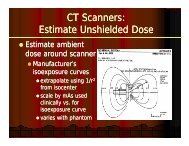
CT Scanner <strong>Shielding</strong>: Overview• Estimate unshielded weekly kerma in occupiedarea near scanner, K un– Use DLP and # patients to state workload• Know P/TP / T• Barrier requires transmission B =K• Get barrier thicknessun– Simpkin Health Phys 58, , 363-7: 1990 (refit in<strong>NCRP</strong>-147)• More from Bob Dixon tomorrow40
Result: CT Scanner in a <strong>Shielding</strong> CaveLight-weightconcrete floors/ceilings are oftentoo thin!“Normal” wallshielding to 2.1 mADD Pb to ceiling(~1 mm)CTScannerADD Pb towall above2.1 m (~1mm)typ 3 mADD Pb to floor(~1 mm)41
Surveys of X-ray <strong>Shielding</strong>• After installation of shielding, should inspect <strong>for</strong>voids in the shielding– Lead-lined dry wall installed upside down= big gap inthe shielding near the floor– Lead in walls not lapped into door/window frames– Gaps between lead sheets– Holes (e.g. electrical loutlets, t junction boxes, plumbing,air conditioning ducts) put into installed shielding. Suchvoids must be backed with shielding materials.• Do inspection by– Visually– By transmission survey with nuclear source & sensitivesurvey meter (GM or NaI)42
Surveys of X-ray <strong>Shielding</strong>• After installation of shielding, should assureadequacy of installed barriers. (That is, “Are theythick enough?”)– Visual linspection i be<strong>for</strong>e walls are closed up.– Transmission measurements through barriers• Generally ypoint measurements that may not be typical of wholebarrier.• Sources:– Gamma ray source (but don’t violate any licensing issues!)– X-ray source (but don’t burn up the x-ray tube)– Difficulties may arise if evaluator uses differentassumptions from designer.43
Surveys of X-ray <strong>Shielding</strong>• Can turn such transmission i measurementsaround and redo the shielding calculation topredict the maximum number of patientstthat can be imaged in the room withoutexceeding P/T.44
<strong>NCRP</strong> <strong>Report</strong> <strong>#147</strong> Conclusions I• Design goals, P:– Kerma in Controlled areas = 5 mGy y -1– Kerma in Uncontrolled areas = 1 mGy y -1• Will assure general population dose limit of 0.25 mSv y -1 isn’tviolated• Reasonable occupancy factors, T:– <strong>for</strong> individuals in uncontrolled areas– effect is to increase kerma to P/T• Transmission, B, is ratio of kermas with andwithout shielding– fit to Archer equation– “hard” HVL results from beam hardening45
<strong>NCRP</strong> <strong>Report</strong> <strong>#147</strong> Conclusions o sII• Workload, W– Quantifies x-ray usage– At a given kVp, shielded and unshielded kermasare ∝ W– W distributed over a range of kVp values. Thisdistribution determines• unshielded kerma• transmission– Workloads surveyed in clinical sites used in<strong>Report</strong>46
<strong>NCRP</strong> <strong>Report</strong> <strong>#147</strong> Conclusions III• <strong>Shielding</strong> models in <strong>NCRP</strong>-147 useful <strong>for</strong>radiography, R&F, mammography, chest,Interventional Labs, etc.– Extensions to <strong>NCRP</strong> Rept-49 models– Unshielded kerma per patient– NT/Pd 2 <strong>for</strong> “representative” radiographic & R&Frooms• CT shielding– Workload expressed as DLP and # patients– Existing floors and ceiling often inadequate <strong>for</strong>modern, multislice CT scanners47