Bedienungsanleitung K 100 Cl2 - Dr. A. Kuntze GmbH
Bedienungsanleitung K 100 Cl2 - Dr. A. Kuntze GmbH
Bedienungsanleitung K 100 Cl2 - Dr. A. Kuntze GmbH
- No tags were found...

You also want an ePaper? Increase the reach of your titles
YUMPU automatically turns print PDFs into web optimized ePapers that Google loves.
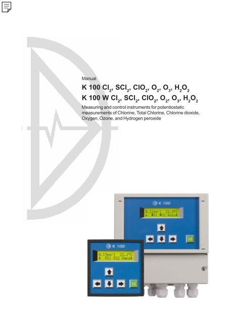
ManualK <strong>100</strong> Cl 2, SCl 2, ClO 2, O 2, O 3, H 2O 2K <strong>100</strong> W Cl 2, SCl 2, ClO 2, O 2, O 3, H 2O 2Measuring and control instruments for potentiostaticmeasurements of Chlorine, Total Chlorine, Chlorine dioxide,Oxygen, Ozone, and Hydrogen peroxide
<strong>Dr</strong>. A. <strong>Kuntze</strong>Gutes Wasser mit System<strong>Dr</strong>. A. <strong>Kuntze</strong> <strong>GmbH</strong>Robert-Bosch-Str. 7aD-40668 MeerbuschTel. +49-21 50-70 66-0Fax +49-21 50-70 66-60info@kuntze.comwww.kuntze.com
Contents1. Your K <strong>100</strong> ..................................................................................................... 41.1 General and Safety instructions ............................................................... 51.2 Application ............................................................................................... 61.3 Intended use ............................................................................................ 61.4 Features................................................................................................... 71.5 Technical data .......................................................................................... 81.6 Declaration of conformity .......................................................................... 92. Instructions for installation and connections ........................................... 102.1 Dimensions ............................................................................................ 112.2 Installation K <strong>100</strong> ................................................................................... 122.3 Installation K <strong>100</strong> W ............................................................................... 132.4 Installation of ASR module (instruments W only) .................................... 142.5 Installation of the RS module (instruments W only) ................................ 152.6 Connection diagram K <strong>100</strong> ..................................................................... 162.7 Connection diagram K <strong>100</strong> W ................................................................. 173. Operation of the instrument....................................................................... 183.1 How to adjust parameters ....................................................................... 193.2 Where to look for information .................................................................. 203.3 Menu overview ........................................................................................ 214. Code and laguage ...................................................................................... 225. Adjustment of the meter ............................................................................ 235.1 Calibration .............................................................................................. 245.2 Temperature compensation .................................................................... 255.3 Automatic sensor cleaning ASR (option) ................................................. 266. Adjustment of the controller ...................................................................... 276.1 ON/OFF controller .................................................................................. 286.2 P / PI controller as impulse-frequency controller ..................................... 296.3 P / PI controller as pulse-pause controller .............................................. 306.4 Activation and deactivation of the controller............................................. 316.5 Turn-on delay ......................................................................................... 316.6 External controller stop (digital input) ..................................................... 316.7 Manual operation of the relays ................................................................ 326.8 Dosage check ........................................................................................ 337. Data output.................................................................................................. 347.1 Current output ........................................................................................ 347.2 Current output as controller output ......................................................... 347.3 Serial interface RS485 (option) ............................................................... 348. Limit values and Alarm .............................................................................. 358.1 Alarm ..................................................................................................... 368.2 Configuration of the alarm relay .............................................................. 378.3 Error messages ...................................................................................... 389. Operation and maintenace........................................................................ 3910. Service ...................................................................................................... 41Index ............................................................................................................... 42Customer settings - for reference! ................................................................. 44K <strong>100</strong> (W) Cl 2, SCl 2, ClO 2, O 2, O 3, H 2O 23
1. Your K <strong>100</strong>Is an instrument by <strong>Dr</strong>. A. <strong>Kuntze</strong> <strong>GmbH</strong> which offers high quality and reliability foryears.It is one of our economy series K <strong>100</strong> with which we are trying to meet the risingdemand for low cost / high end instrumentation.The K <strong>100</strong> instruments are defined by an excellent value for money. They weredevelopped to maximize functionability on standard applications.Operation requirements are reduced to an absolute minimum: The instrument isdelivered ready-to-use with a pre-adjusted working potential suitable for yourmeasurement. It is even pre-calibrated, so you will receive approximate measuredvalues immediately after installation. Single-point calibration is used to determine theelectrode´s response characteristic.K <strong>100</strong> instruments can be equipped, even at a later date, with the Automatic Cleaningfunction ASR. The patented electrochemical cleaning function prevents coatings oflime, rust, or grease, and drastically reduces maintenance requirements.All K <strong>100</strong> instruments have an integrated controller which provides bidirectional PIcontrol, via two relays or as a steady-state controller via the analog output. You candefine a turn-on delay to prevent incorrect dosage after power failure and operate thecontroller by remote control. Connect a level sensor, and the fail-safe will shut downthe controller automatically in a low water situation. Activate the dosage check functionto get an alarm if dosage achieves no results, indicating damages in the feeding lines.You can configure the alarm relay as NO or NC contact, so that power failure gives analarm, too, and as pulse contact instead of permanent contact, to fit all kinds ofsubsequent security systems. Furthermore, input errors and low water are nowindicated via anlog output in addition to the relay/display indication.Let´s not forget the alarm function with minimum and maximum limit and turn-ondelay...You have certainly made a good choice. On the following pages you learn more aboutyour K <strong>100</strong>. If, however, you have further questions or are looking for information notincluded in this manual or if you are interested in supplementing products likesensors or flow cells or in our other instrument series, just give us a call - we will bedelighted to help you!4K <strong>100</strong> (W) Cl 2, SCl 2, ClO 2, O 2, O 3, H 2O 2
1.1 General and safety instructions1.1 General and Safety instructionsThis manual applies to the following instruments:Instrument and typeRevision dateK <strong>100</strong> Cl 2, K <strong>100</strong> W Cl 212/10K <strong>100</strong> SCl 2, K <strong>100</strong> W SCl 212/10K <strong>100</strong> ClO 2, K <strong>100</strong> W ClO 212/10K <strong>100</strong> O 2, K <strong>100</strong> W O 212/10K <strong>100</strong> O 3, K <strong>100</strong> W O 312/10K <strong>100</strong> H 2O 2, K <strong>100</strong> W H 2O 212/10It contains technical information for the installation, start-up and maintenance. If youhave any questions not included in this manual please contact your supplier or theofficial representative of <strong>Dr</strong>. A. <strong>Kuntze</strong> <strong>GmbH</strong> in your country.We would like to point out that the warranties specified in our general tradingconditions are valid only if- installation, connections, adjustments, start-up, and maintenance of theinstrument are carried out by authorized personnel with adequate qualification.- the instrument is used according to the description in this manual.Please check for damages immediately after receiving the instruments and report anydamages within 24 hours to the delivering company. Never work with a damagedinstrument.Keep this manual at a safe place where you can always look up the safety instructionsand the informations on handling and usage. According to DIN 61010 the manual ispart of the product and must be maintained as long as the instrument is used, andgiven to the next owner if the instrument is sold.This instrument was designed and built according to the safety measurements forelectronic devices and has left our company in perfect working condition. To preservethis condition and to ensure safe usage follow all instructions carefully and pay specialattention to all warnings issued in this manual. If the instrument is visibly damaged orhas been stored inappropriately or if there are any doubts concerning safe usage, shutit down and make sure it cannot be restarted by accident.You will notice that important safety instructions are highlighted:CAUTION highlights instructions for the protection of people. Disregarding theseinstructions may cause accidents and injuries!ATTENTION higlights instructions for the protection of the instrument and theequipment. Disregarding these instructions may lead to damage ordestruction of the instrument or equipment!NOTE is used to highlight interesting details.K <strong>100</strong> (W) Cl 2, SCl 2, ClO 2, O 2, O 3, H 2O 25
1.2 Application and intended use1.2 ApplicationThe instruments K <strong>100</strong> <strong>Cl2</strong> and K <strong>100</strong> W <strong>Cl2</strong> can be used to measure theconcentration of free Chlorine in water. The other instruments measure theconcentrations of their specific parameters. Alle have an integrated controller with twoset points. With this you can control actuators such as dosing pumps or valves to addchemicals until the desired concentration is reached and maintained.Applications are detoxication of industrial waste water, water treatment, anddesinfection.While the controller is set to Automatic, it controls independently the dosing of possiblyhazardous chemicals, according to the measured values.For safety measures, both the measurement and the calibration are checked forfailure. Failures are indicated in the display and via the alarm relay, which can set off ahorn or lamp or relate to a central control. If that failure makes control unreliable, thecontroller is automatically switched off until the failure has been taken care off.CAUTIONThe instrument checks the input signals, the calibration results, andthe water flow, if a flow sensor is connected. It cannot detecterroneous settings or failures in the treatment system, nor can itcheck for plausibility! The safety of the system of which theinstrument is part of, lies within the reach of responsibility of whoeverbuilt the system.1.3 Intended useUse these instruments only for the monitoring and control of water.Use only sensors, fittings, and accessories of <strong>Dr</strong>. A. <strong>Kuntze</strong>, since instruments andsensors are attuned.Ensure that the required measuring conditions are constantly maintained, such asflow, pressure, temperature, etc.Set-up the instrument according to this manual. Carry out all the steps described, andcheck all measurements and settings before you activate the controller.Use all available safety measures such as the alarm relay, the dosage check, and thelack-of-water indication.Regularly check that all safety measures are in good working order.CAUTION The protection built into the instrument is impaired if they are not usedas intended!6K <strong>100</strong> (W) Cl 2, SCl 2, ClO 2, O 2, O 3, H 2O 2
1.4 Features1.4 FeaturesMeterMeasuring ranges 0.00 - 4.00 mg/l Cl 2free Chlorine (K <strong>100</strong> (W) Cl 2)0.00 -10.00 mg/l TCl 2total chlorine (K <strong>100</strong> (W) SCl 2)0.00 - 4.00 mg/l ClO 2Chlorine dioxide (K <strong>100</strong> (W) ClO 2)0.0 - 20.0 mg/l O 2Oxygen (K <strong>100</strong> (W) O 2)0.00 - 4.00 mg/l O 3Ozone (K <strong>100</strong> (W) O 3)0.00 -30.00 mg/l H 2O 2Hydrogen peroxide (K <strong>100</strong> (W) H 2O 2)-30.0 - 140.0 °CDisplayMeasured value and temperature with dimensionStatus display sensor, calibration, controller & alarmTemperature compensation manual or automatic with Pt<strong>100</strong> (NTC for O 2)Calibration1-point calibration; for Oxygen measurements in airAveragingcan be activated and deactivated via menuAutomatic Sensor cleaning (option) automatically recognised when connectedControllerSet pointsController typesHysteresisP range X PIntegral time T NLeast pulsePulse+Pause timeImpulse frequencyTurn-on delayDosage checkAlarm function2 set points with adjustable directionON/OFF controller with hysteresisP controller as Pulse-Pause-, Impulse-Frequency- or steady controllerPI controller as Pulse-Pause-, Impulse-Frequency- or steady controllerajustable within the measuring rangeadjustable within the measuring range0 - 2000 sec.0.1 - 9.9 sec.02 - 99 sec.<strong>100</strong> - 7200 pulses/h0 - 200 sec.0 - 90 minmin. and max. limit and onset delayConnectionsRelaysAnalog output3 potential-free contacts (2x controller, 1x alarm)6 A, 250 V, max. 550 VA0/4-20 mA galvanically isolated, max. loading 500 OhmAnalog inputs 1 measuring input for Cl 2, TCl 2, ClO 2, O 2, O 3, or H 2O 21 measuring input for temperature sensorDigital inputSerial interface(Option)external controller stop or low water indicationNC or NO selectable via menuRS485, Baud rate 9600, data formate 8Bit,1start and 1stop bit, no parityK <strong>100</strong> (W) Cl 2, SCl 2, ClO 2, O 2, O 3, H 2O 27
1.5 Technical data1.5 Technical dataFeature K <strong>100</strong> K <strong>100</strong> WviewInstallation panel-type housing wall-mounting housingDimensions 96 x 96 x 135 mm (WxHxD) 165 x 160 x 85 mmWeight 0.8 kg 1.0 kgTerminals screw terminals spring-loaded terminalsfor cables up to 1.5mm 2 for cables up to 1.5mm 2Protection class Front IP54 IP65Power supply230 V +6/-10%, 40..60 Hz, optionally 117 V or 24 Vinternal fuse none 230V: 63mA HRC117V: 125mV HRC24V: 800mA NRCPower consumption 10VAContact rating6 A/ 250 V, max. 550 VA resistive load(with RC protective circuit)Operation temperature 0 - 50°CStorage temperature-20 - +65°CHumiditymax. 90% at 40°C non condensing8K <strong>100</strong> (W) Cl 2, SCl 2, ClO 2, O 2, O 3, H 2O 2
1.6 Declaration of conformity1.6 Declaration of conformityK <strong>100</strong> (W) Cl 2, SCl 2, ClO 2, O 2, O 3, H 2O 29
2. Instructions for installation and connections2. Instructions for installation andconnectionsInstallation:On the next pages you will find detailed instructions for the installation.For panel-type meters you have to prepare an opening of 92x92mm. Install theinstrument and fix it with the two mounting clips which were part of the delivery.You can install instruments in wall-mounting housings either by hanging them uponthe center slot or by sliding the slot under a screw, which is an alternative for limitedspace. Either way you have to fix it additionally with two screws.ATTENTION Install the instrument in a place where it is not put under mechanicalor chemical strain!Mind the protection class:K <strong>100</strong>: Front IP54K <strong>100</strong> W: IP65 (closed terminal cover)Connections:You will find detailed connection diagrams on the following pages.Before connecting the power supply check the information on the instrument label!ATTENTION Input, output and control lines must be installed separate from eachother and separate from power lines!For inputs and outputs use screened lines and connect the screen on one side only.The potentiostatic measurement is interference-sensitive, especially when usingmembrane sensors. Use a special screened cable. Membran sensors are deliveredcomplete with cable.For the connection of temperature sensors use a low-resistance cable with a largediameter.When using the relays, mind that with inductive loads, interference must besuppressed. If that is not possible, the relay must be protected at the terminal block inthe K <strong>100</strong> by a resistance-capacitance filter or, in case of direct current, by a freewheelingdiode.RCCurrent up to Capacitor C Resistance R60 mA 10 nF 260 V 390 Ohm 2 Watt70 mA 47 nF 260 V 22 Ohm 2 Watt150 mA <strong>100</strong> nF 260 V 47 Ohm 2 Watt1,0 A 220 nF 260 V 47 Ohm 2 Watt10K <strong>100</strong> (W) Cl 2, SCl 2, ClO 2, O 2, O 3, H 2O 2
2.1 Dimensions2.1 DimensionsK <strong>100</strong>K <strong>100</strong> WK <strong>100</strong> (W) Cl 2, SCl 2, ClO 2, O 2, O 3, H 2O 211
2.2 Installation K <strong>100</strong>2.2 Installation K <strong>100</strong>Prepare anopening of 92 x92 mm.Install theinstrument fromthe front sideand fix it with thetwo mountingclips which werepart of thedelivery.Screw tight untilthe instrument isfixed perfectly.12K <strong>100</strong> (W) Cl 2, SCl 2, ClO 2, O 2, O 3, H 2O 2
2.3 Installation K <strong>100</strong> W2.3 Installation K <strong>100</strong> WRemove the terminalcover.<strong>Dr</strong>ill three holes (max.M5) according to thedrawing. Mind that thereare two ways forinstallation: (1) You canhang the instrument uponthe upper screw. In thatcase drill the upper hole120mm above the lowertwo. (2) Or you can slipthe fixture on the back ofthe isntrument under theupper screw. In that casethe upper hole has to beanother 15mm higher.Mount the instrument andfix it with the two lowerscrews. Close theterminal cover or startwith the connections.K <strong>100</strong> (W) Cl 2, SCl 2, ClO 2, O 2, O 3, H 2O 213
2.4 Installation of ASR module2.4 Installation of ASR module (instruments W only)The Automatic Sensor Cleaning function ASR can be added later on, at least withinstruments in wall-mounting housing (production date 1-2011 or later).ATTENTIONCAUTIONASR cannot be used with membrane-covered sensors (TCl, Oxygen).Switch off the power supply before opening the instrument!ATTENTION Make sure that the inside of the instruemnt does not get wet!Remove the covers of the front screws, unscrew the screws, and open the front. Mindthat the connection of the key pad does not come loose, or if it does, do not forget toreplace it before closing the instrument.The ASR board is installed on the left side of theinstrument, directly above the terminals.Attention: Instruments delivered without ASR boardhave protective covers over the two 2-pinconnectors that have to be removed beforeinstallation of the board.Install the board with its 6-pin plug over the 6-pinsocket of the instrument and its two 2-pin socketsover the two 2-pin plugs of the instrument. Mind thatthe pins are not broken or bent during theinstallation and that the boards sits properly.This is how it looks with the board in place.Before closing the instrument, make sure thatthe 6-pin connection to the front´s key pad issecurely in place.Close the front, fix it with the screws, andreplace the screw covers.14K <strong>100</strong> (W) Cl 2, SCl 2, ClO 2, O 2, O 3, H 2O 2
2.5 Installation of RS module2.5 Installation of the RS module (instruments W only)The serial interface can be added later on, at least with instruments in wall-mountinghousing (production date 1-2011 or later).CAUTIONSwitch off the power supply before opening the instrument!ATTENTION Make sure that the inside of the instruemnt does not get wet!Remove the covers of the front screws, unscrew the screws, and open the front. Mindthat the connection of the key pad does not come loose, or if it does, do not forget toreplace it before closing the instrument.The RS board is installed on the left side of theinstrument, directly above the terminals.Install the board with its 10-pin socket over the 10-pin plug of the instrument. Mind that the pins arenot broken or bent during the installation and thatthe boards sits properly.The board is installed with the 10-pin connectionon the right side and the board facing left. It sits atan angle to make room for the ASR boardunderneath.This is how it looks with the RS board in place.This is how it looks with both boards in place.Before closing the instrument, make sure thatthe 6-pin connection to the front´s key pad issecurely in place.Close the front, fix it with the screws, andreplace the screw covers.K <strong>100</strong> (W) Cl 2, SCl 2, ClO 2, O 2, O 3, H 2O 215
2.6 Connection diagram K <strong>100</strong>K <strong>100</strong>2.6 Connection diagram K <strong>100</strong>123456789 +10 -11 +12 -1314SensorPt<strong>100</strong>/NTC0/4-20 mADig. IN-RS 485594837261+Rel 1Rel 2Rel 3LNPE151617181920212223242526MConnection Terminals Note<strong>Cl2</strong>/ClO2/O3 sensor 1 - 4 1 = Screenor H2O2 sensor2 = Measuring electrode = brown3 = reference electrode = white4 = counter electrode = blueOxygen sensor 1 - 4 1 = free2 = measuring electrode = core3 + 4 together = counter electrode = brownTCl sensor 1 - 4 1 = reference = yellow2 = measurement = green3 = - 6 V = white4 = + 6 V = brownPt<strong>100</strong> / NTC 5 + 6Analog output 9 + 10 9 = +, 10 = -, max. load 500 OhmDigital input 11 + 12 11 = +, 12 = -, external controller stopand / or low water indicationRelay 1 18 + 19Relay 2 20 + 21Relay 3 22 + 23 Alarm relayPower supply 24 - 26 Check information on instrument label!RS485 (Option) Sub-D 3 = +, 8 = -4/7 bridged activates terminating resistance16K <strong>100</strong> (W) Cl 2, SCl 2, ClO 2, O 2, O 3, H 2O 2
Display2.7 Connection diagram K <strong>100</strong> WK <strong>100</strong>2.7 Connection diagram K <strong>100</strong> WM1 2 3 4 5 6 7 10 11 12 13 14 15 16 17 18 19 20 21 22+ -Sensor Pt<strong>100</strong>/NTC 0/4-20 mA Rel. 1 Rel. 2 Rel. 3 L N PEA23 24 25 26 27 28- + +RS 485Dig. INConnection terminals Note<strong>Cl2</strong>/ClO2/O3 sensor 1 - 4 1 = Screenor H2O2 sensor2 = Measuring electrode = brown3 = Reference electrode = white4 = Counter electrode = blueOxygen sensor 1 - 4 1 = free2 = measuring electrode = core3 + 4 together = counter electrode = brownTCl sensor 1 - 4 1 = reference/GND = yellow2 = Measuring signal = green3 = - 6 V = white4 = + 6 V = brownPt<strong>100</strong> / NTC 6 + 7Display-Kontrast Display Potentiometer to adjust brightnessAnalog output 11 + 12 11 = +, 12 = -, max. load 500 OhmRelay 1 14 + 15Relay 2 16 + 17Relay 3 18 + 19 Alarm-RelaisPower supply 20 - 22 Check information on instrument label!RS485 (Option) 23 + 24 23 = -, 24 = +Jumper A activates terminating resistanceDigital input 26 - 28 26 = +, 27 = -, external controller stopand / or low water indication28 = +24 V DC for inductive flow sensorsK <strong>100</strong> (W) Cl 2, SCl 2, ClO 2, O 2, O 3, H 2O 217
3. Operation of the instrument3. Operation of the instrument1 2 3 4 5 60.49 mg/l 25.0°CS1 S2 Man7 8 9 10 111 Measured value2 Status relay 13 Status relay 2 relay OFF relay ON4 Temperature5 ControllerAUTO: controller ONMAN : controller OFF(manual operationof the relays)HOLD: freezes analogoutput and limit function6 Orientation aids7 Key left ()8 Key up ()9 Key down ()10 Key right ()When turned on the instrument shows the measured value and temperature togetherwith the controller mode (Man) and the status of the relays S1 and S2 (both OFF).With five membrane keys you can move within the menu:With key you enter the main menu.With keys and you move up and down in the menu.With key you adress a menu or parameter.With key you leave a menu or store a change.For your convenience triangles in the display indicate the directions you can take fromyour position in the menu.From the display of the measured values you can switch the controller ON and OFFwith key in the order: AUTO HOLD MAN AUTO.With key „M“ you get back to the display of the measured values from any point in themenu. Changes that have not been stored will be lost.NOTEThe instruments K <strong>100</strong> and K <strong>100</strong> W differ only in housing. Operationand menus are the same.18K <strong>100</strong> (W) Cl 2, SCl 2, ClO 2, O 2, O 3, H 2O 2
3.1 How to adjust parameters3.1 How to adjust parametersTemp. Comp. Manual Comp.1) When you adress a parameter the actual setting isdisplayed.Temp. Comp. Automat. Comp.Temp. Comp. Manual Comp.2) Switch to the next alternative setting with key.3) When you have come to the last alternative, pressing thekey once more will bring you back to the start.Selection between alternativesFor many parameters you have the choice between two or more alternatives, e. g.between manual and automatic temperature compensation. For these parameters youneed only key. Switch from one alternative to the next until you either come back towhere you started or until you reach the alternative you were looking for.With these parameters any changes are immediately valid - there is no need to storethe change.Enter code 058 Code1) Adress the parameter with key.Enter code 058 Code2) A double triangle appears behind the number indicatingthat the number can be changed now with keysand .Enter code 062 Code3) Store the new value with key. The double triangledisappears - the new value is stored.Adjustment of numerical parametersNumerical parameters can only be altered when a double triangle is visible behind thenumber. This double triangle appears when you adress the parameter with key.Adjust the parameter with keys and . A short pressure on the key changes the lastdecimal by 1. If you keep the key pressed, the value will continue changing until thepressure is released.Store the changes with key. The double triangle disappears.NOTEIf you do not want to store the change, press key „M“ instead ofkey.K <strong>100</strong> (W) Cl 2, SCl 2, ClO 2, O 2, O 3, H 2O 219
3.2 Where to look3.2 Where to look for information0.48 mg/l 25.0°CS1S2 AutoMain menuCalibrateTemp. Comp.Enter passwordSet pointsLimit valuesMain displayEnter the menu with key .Information is in chapter:Adjustment of the meter - calibrationAdjustment of the meter - temperature compensationCode and languageAdjustment of the controller - ON/OFF, P/ PI controllerLimit values and alarmBasic settingsServiceBasic settingsCal. Pt/NTCContr. settingsStart delayAnalog outputLanguageBus adressAveragingTemp. coeff.CleaningDig. inputAlarm relayInformation is in chapter:Adjustment of the meter - temperature compensationAdjustment of the controller - ON/OFF, P/PI controllerAdjustment of the controller - activation and deactivationData outputCode and languageData outputAdjustment of the meter - averagingAdjustment of the meter - temperature compensationAdjustment of the meter - automatic Sensor cleaningAdjustment of the controller - activation and deactivationLimit values and alarmMain menu and basic settingsThe parameters are sorted into two menus: In the main menu you will find all functionswhich are used regularly, such as calibration. The menu basic settings contains allparameters which are set just once during start-up.On the following pages you will find information on how to adjust parameters andwhich parameters you need for which application, in the following order:1) General adjustments: password and language2) Adjustments for measurement: calibration, temperature compensation,averaging, flow, and cleaning (option)20K <strong>100</strong> (W) Cl 2, SCl 2, ClO 2, O 2, O 3, H 2O 2
3.3 Menu overview3.3 Menu overview0.48 mg/l 25.0°CS1S2 AutoPress key to enter the menu.Main menuCalibrateTemp. comp.Enter passwordSet pointsLimit valuesBasic settingsServiceDPD calibration0.48 mg/lSlope025 mVTemp. comp.Manual comp.Temperature25.0 °CEnter password056 CodeSet point S11.50 mg/lP range S10.20 mg/lIntegral time S<strong>100</strong>0 sec.Set point S2P range S2Integral time S2Limit S11.00 mg/lLimit S20.30 mg/lstart delay005 sec.control. modeAuto+ManBasic settingsCal. Pt/NTCContr. settingsStart delayAnalog outputLanguageBus adressAveragingCal Pt/NTC0.0 °CPulse-freq. S<strong>100</strong>*<strong>100</strong>/hDirection S1raiseDirection S2lowerHysteresis0.01 mg/lPulse+Pause10 sek.Min. pulse0.1 sec.Dosage checkS1 060minStart delayONStart delay180 sec.Select output0 - 20 mABegin 0/4mA0.00 mg/lEnd20 mA4.00 mg/lAnalog outputMeasuring valueWe speakEnglishBus adressNr. 00AveragingONServiceProduct infoAnalog inputsClear memoryUnit no.Nr. 041Software dateM/Y 1.00Product. dateM/Y 1.00Analog inputsinput 1 003 mVAnalog inputsinput 2 25.0°CClear memoryPress&Temp. coeff.CleaningDig. inputAlarm relayTemp. coeff.0.0%/KCleaning1/dayStart delay6.0 hBase-load dosingOFFDig. inputNOAlarm relayNormally openPulse contactwith ext.contr.K <strong>100</strong> (W) Cl 2, SCl 2, ClO 2, O 2, O 3, H 2O 221
4. Code and laguage4. Code and laguageMain menu..Enter passwordEnter passwordEnter Password056 CodeEnter passwordTo get access to the various parameters you have to enter the correct password:Code 11 gives access to the parameters „calibration“, „temperaturecompensation“, and „set points“.Code 86 gives access to all parameters and functions.With any other number it is impossible to select, view or change any parameter..Main menu.Basic settingsBasic settings..LanguageLanguageWe speakenglishLanguageFor the communication with the instrument you can choose from a variety oflanguages.Since choosing a language is part of the basic settings, it requires code 86. If adifferent code is set, you will be asked to enter the correct password.22K <strong>100</strong> (W) Cl 2, SCl 2, ClO 2, O 2, O 3, H 2O 2
5. Adjustment of the meter5. Adjustment of the meterHauptmenüCalibrateTemp. comp.....Basic settingsCalibration of the measurement and display of slope.Selection between automatic and manual temperaturecompensation, adjustment of temperature for manualcompensation.Basic settingsCal. Pt/NTC.AveragingTemp. coeff.CleaningCalibration of the temperature measurementActivation of averaging functionCoefficient for linear temperature compensationCleaning interval and delay time (option)Potentiostatic measurements require a 1-point calibration:Since the measurement depends upon the flow-rate and calibration solutions wouldnot be stable anyway, the sensor cannot be taken out of the armature for calibration, asis done with pH sensors. Instead the actual concentration of the test water isdetermined by an alternative method, for example photometrically with DPD, and thisvalue is entered as calibration value. Calibration of the Oxygen measurement issimpler, using the Oxygen concentration of the ambient air.The measurement is influenced by temperature. This influence can be compensatedmanually or automatically. For manual compensation the temperature is enteredmanually, for automatic compensation temperature has to be measured with atemperature sensor. For the temperature compensation a linear coefficient can beadjusted as %/K.For smoother measured values activate the averaging function.If you have purchased an instrument with Automatic Sensor Cleaning ASR, the basicsettings will include „cleaning“ where you can activate the automatic cleaning, definethe interval between subsequent cleaning cycles and the time for the first cleaningcycle.NOTE The menu „cleaning“ appears automatically when an ASR-board isinstalled.K <strong>100</strong> (W) Cl 2, SCl 2, ClO 2, O 2, O 3, H 2O 223
5.1 Calibration5.1 CalibrationMain menuCalibrationDPD CalibrationDPD Calibration0.48 mg/lSlope025 mVEnter the concentration determinedby photometric DPD measurement ascalibration value.Calibration of the measurement of Cl 2, TCl 2, ClO 2, O 3, and H 2O 21) Switch off the controller. Take a sample of the test water flowing out of thearmature and determine the concentration by photometric DPD measurementor a similar reference method.2) Enter the determined concentration and calibrate by pressing keys and :Start with key and then - while still applying pressure on this key - additionallypress key.3) Check the displayed slope before switching on the controller.Zero-point correctionIf you set the DPD value to 0.00mg/l, the calibration is interpreted as zero-pointcorrection, and the instruments substracts this value from all subsequentmeasurements. However, zero-point correction is only advisable if Analog input 1 in theservice menu differs noticeably from zero in disinfectant-free water.Calibration of the Oxygen measurementThe Oxygen measurement is calibrated in water-saturated air.1) Switch off the controller. Take the sensor out of the armature, dry the sensor tipcarefully with a napkin, hold it in the air above water with the membrane pointingdown and wait until the reading is stable.2) Calibrate by pressing keys and : Start with key and then - while stillapplying pressure on this key - additionally press key .3) Check the displayed slope, put the sensor back in the armature, wait until thereading is stable, then switch the controller on again.NOTEThe Oxygen measurement strongly depends on temperature. Makesure that automatic calibration is selected during calibration.24K <strong>100</strong> (W) Cl 2, SCl 2, ClO 2, O 2, O 3, H 2O 2
5.2 Temperature compensation5.2 Temperature compensationMain menu.Temp. comp.....AutomaticcompensationTemp. Comp.Auto Comp.ManualcompensationTemp. Comp.Manual Comp.Temperature25.0 °CBasic settingsBasic settingsCal Pt/NTC...Temp. coeff.Cal Pt/NTCCal. Pt<strong>100</strong>/NTC0.0 °CTemp. coefficientTemp. coeff.0.0 %/KChoose between manual and automatic temperature compensation.Mind that for automatic compensation the temperature sensor should measure thetemperature in the vicinity of the sensor. If temperature sensor and potentiostaticsensor are not immersed in the same solution, better switch to manualcompensation. Enter the temperature manually. The instrument will then compensatethe temperature effect of this temperature.Temperature coefficientWith the temperature coefficient you can adjust the degree of compensation. Thecoefficient is given as %/K. For example, with a coefficient of 2%/K two percent of themeasured value are substracted per degree of temperature above 25°C.Calibration of the temperature measurementSince the temperature sensor is connected with a twin-core cable, slight deviationsmight occur between measured and real temperature. These deviations can beeliminated by calibration.During start-up, measure the temperature manually and enter a correction term so thatthe display shows the exact temperature.K <strong>100</strong> (W) Cl 2, SCl 2, ClO 2, O 2, O 3, H 2O 225
5.3 Automatic sensor cleaning ASR (option)5.3 Automatic sensor cleaning ASR (option)Main menu..Basic settingsBasic settings..CleaningCleaningCleaningevery 7 daysStart delay6.0 hbase-load dosingOFFThe patented Automatic Sensor Cleaning ASR prevents staining and passivatingcoatings and keeps the surface of metal sensors clean throughout the measurement.The cleaning is an electrochemical one: in adjustable intervals the instrument appliesa strong voltage to the electrode to produce Hydrogen and Oxygen from thesurrounding water. This method needs no addition of chemicals.The cleaning process takes about 30 seconds. During this time measurement is notpossible, and after cleaning the sensor needs some time for polarisation. Therefor thedisplay and the analog output will show the last measured value for five minutes, andthe message „cleaning in progress“ is displayed. As a safety measure, attempts tocalibrate within these five minutes are ignored.Activation and timingThe cleaning is activated by setting the cleaning function from „deactivated“ to 1/day(every 24h), 2/day (every 12 h), every 3days, or every week. The first cleaning starts assoon as the function is activated, and subsequent cleanings are carried out after 24h,or 12h, or the specified period of days.The start delay allows to select a more convenient cleaning time, e.g. in the night. Afteractivation the cleaning is delayed by the set time.NOTE Whenever the instrument indicates „ext. contr. stop“, cleaning is notcarried out.Since during ASR no measurement is carried out, the controller is shut off until reliablemeasured values are available again. For applications in open systems, where thisshut-down will lead to an intolerable loss of disinfectant concentration, you can selecta base-load dosing - during ASR the instrument will continue dosing with the averagecontroller output of the last 30 minutes.CAUTION This dosing is not controlled by measurements! Only use it if there isno risk of overdosing!NOTENOTEWhen using the base-load dosing, set the delay to min. 0.5h to get areliable average.Interval settings are updated only directly after the cleaning and afteractivation. If you change the interval between cycles, the new settingswill be effective only after the next cleaning.26K <strong>100</strong> (W) Cl 2, SCl 2, ClO 2, O 2, O 3, H 2O 2
6. Adjustment of the controller6. Adjustment of the controllerMain menu..Set points..Basic settingsBasic settings .Contr. settingsTurn-on delaySelection of ON/OFF, P or PI controller, adjustment of P rangesand I functions for 2 set points.Adjustment of frequencies and pulse/pausetimes, hysteresis, direction of the control actionActivation of the controller after start-up or powerinterrupt is delayed by the time specified here.For any type of controller you have to enter one or two set points, and you have to tellthe instrument whether these set points are reached by increasing or decreasing themeasured value.You can choose between three different controller versions:ON/OFF controllerThe ON/OFF controller switches ON if the measured value exceeds the set point andOFF if it drops back below it or vice versa. Dosage is always carried out with <strong>100</strong>%(ON) or 0% (OFF). The parameter for an ON/OFF controller is the hysteresis.P controllerThe P controller or proportional controller reduces the dosage in the vicinity of the setpoint proportional to the control deviation. This is easily achieved if the analog output isused as steady control output. If the relays are used, the proportional reduction isachieved by either reducing the switch frequency (Impulse-frequency controller) orreducing the time within a given period of time in which the relay is ON (pulse-pausecontroller). The parameters for a P controller are the P range and the impulsefrequencyor the pulse+pause time and the minimum pulse.PI controllerThe PI controller is a P controller with an additional I function. Adjustments andparameters are the same as for an P controller. Additionally the integral action timehas to be adjusted which determines the I function. The I function eliminates the Pcontroller´s disadvantage of a remaining steady-state deviation.K <strong>100</strong> (W) Cl 2, SCl 2, ClO 2, O 2, O 3, H 2O 227
6.1 ON/OFF controller6.1 ON/OFF controllerMain menu..Set points....Basic settings .Set pointsSet point S11.50 mg/lP range S10.20 mg/lIntegral time S<strong>100</strong>0 sec.Set point S20.50 mg/lP range S20.20 mg/lIntegral time S2000 sec.Basic settingsContr. settingsrYou can choose different controllerversions for S1 and S2.Controller settings..Direction S1raiseDirection S2lowerHysteresis0.01 mg/lFor an ON/OFF controller you have to set the following parameters:1) Set points S1 and S2Set point S1 refers to relay 1, set point S2 refers to relay 2.2) P range and integral action time for S1 and S2For an ON/OFF controller set P range = 0 and integral time = 0.3) Acting direction for S1 and S2Select „raise“ if the dosage raises the measured value.Select „lower“ if the dosage lowers the measured value.4) optionally a hysteresisThe hysteresis prevents fast switching in the vicinity of the set point. If hysteresis isactivated (by setting a value > 0) the relay switches only when the set point isexceeded by half the hysteresis.28K <strong>100</strong> (W) Cl 2, SCl 2, ClO 2, O 2, O 3, H 2O 2
6.2 P/PI controller as impulse-frequency controller6.2 P / PI controller as impulse-frequencycontrollerMain menu..Set points....Basic settingsSet pointsSet point S11.50 mg/lP range S10.20 mg/lIntegral time S<strong>100</strong>0 sec.Set points S20.50 mg/lP range S20.20 mg/lIntegral time S2000 sec.Basic settings.Contr. settingsYou can choose different controllerversions for S1 and S2.Controller settingsPulse-Freq. S<strong>100</strong>*<strong>100</strong>/hPulse-Freq. S200*<strong>100</strong>/hDirection S1raiseDirection S2lowerFor an impulse-frequency controller you have to set the following parameters:1) set points S1 and S2S1 refers to relay 1, S2 refers to relay 2.2) P range and integral action time for S1 and S2Adjust a P range > 0. For a P controller set integral time = 0, for a PI controller setan integral time > 0.3) pulse-frequencies for S1 and S2Enter the maximum pulse-frequency that corresponds to <strong>100</strong>% dosage.4) the acting direction for S1 and S2Select „raise“ if the dosage raises the measured value.Select „lower“ if the dosage lowers the measured value.K <strong>100</strong> (W) Cl 2, SCl 2, ClO 2, O 2, O 3, H 2O 229
6.3 P/PI controller as pulse-pause controller6.3 P / PI controller as pulse-pause controllerMain menu..Set points....Basic settingsSet pointsSet point S11.50 mg/lP range S10.20 mg/lIntegral time S<strong>100</strong>0 sec.Set point S20.50 mg/lP range S20.20 mg/lIntegral time S2000 sec.Basic settings.Contr. settingsController settingsPulse-Freq. S<strong>100</strong>*<strong>100</strong>/hPulse-Freq. S200*<strong>100</strong>/hDirection S1raiseDirection S2lower..Pulse+Pause10 sMin. pulse0.1 sYou can choose differentcontroller versions for S1and S2.The pulse+pause time mustbe at least twice as long asthe minimum pulse time.For a pulse-pause controller you have to set the following parameters:1) set points S1 and S2S1 refers to relay 1, S2 refers to relay 2.2) P range and integral action timeAdjust a P range > 0. For a P controller set integral time = 0, for a PI controller setan integral time > 0.3) pulse-frequencies for S1 and S2Both frequencies must be set to 00, otherwise the controller will act as an impulsefrequencycontroller.4) the acting direction for S1 and S2Select „raise“ if the dosage raises the measured value.Select „lower“ if the dosage lowers the measured value.5) pulse+pause timeDefine a period of time during which the relay is proportionally to the controldeviation ON (pulse) or OFF (pause), respectively.6) least pulse timeSet a minimum pulse time that the relay has to at least remain open to allow theactuator to react.30K <strong>100</strong> (W) Cl 2, SCl 2, ClO 2, O 2, O 3, H 2O 2
6.4 Activation and deactivation of the controller6.4 Activation and deactivation of the controllerYou can activate and deactivate the controller without any menu. Press key to switchbetween manual operation (controller OFF) and automatic operation (controller ON).The actual operation mode is indicated in the display by MAN or AUTO.WARNINGMake sure that the controller is OFF when connecting dosing pumpsor other actuators!Main menu..Basic settingsBasic settings..Start delay...start delayStart delayOFFTurn-on delayONTurn-on delay180 sec.Digital inputDig. inputDig. inputNODig. inputNC6.5 Turn-on delaySet a delay time which has to pass before the controller is activated after start-up orpower interrupt. This allows the measurement to settle and prevents inappropriatedosage of chemicals.6.6 External controller stop (digital input)You can activate or deactivate the controller with an external switch by using the digitalinput. This feature can also be used as low water indication. Just connect a level orflow sensor to the digital input. At works, the input ist NO (normally open). You canswitch to NC (normally closed) in the basic settings.With selection NO, the controller stops whenever the digital input is closed, with NC, itstops whenever the input is opened.As long as that is the case, the message “external controller stop“ is displayed.K <strong>100</strong> (W) Cl 2, SCl 2, ClO 2, O 2, O 3, H 2O 231
6.7 Manual operation of the relays6.7 Manual operation of the relays0.48 mg/l 25.0°CS1S2 Auto0.48 mg/l 25.0°CS1S2 Man0.48 mg/l 25.0°CS1S2 Man0.48 mg/l 25.0°CS1S2 Man1) If the controller is ON, switch it OFF with key.Instead of „Auto“ the display shows „Man“.2) Switch to the operation mode of S1 with key .The square to the left of S1 starts to flash.3) Switch ON relay 1 with key .The square to the left of S1 gets dark.4) Switch OFF relay 1 again with key.0.48 mg/l 25.0°CS1S2 ManThe square gets light.5) Switch to the operation mode of S2 with key .0.48 mg/l 25.0°CS1S2 ManThe square to the left of S2 starts to flash.6) Switch ON relay 2 with key.0.48 mg/l 25.0°CS1S2 ManThe square to the left of S2 gets dark.7) Switch OFF relay 2 again with key.0.48 mg/l 25.0°CS1S2 ManThe square gets light.8) Leave the operation mode of relay 2 with key .0.48 mg/l 25.0°CS1S2 ManBoth squares appear light, none flashes - You have leftthe operation mode.For manual operation you need no menu.With key you switch OFF the controller.With key you switch between Manual operation operation mode S1 operationmode S2 manual operation.In the operation mode you can Switch ON and OFF the selected relay with key.A flashing square indicates that the relay is in operation mode.A dark square indicates that the relay is swichted ON.A light square indicates that the relay is switched OFF.WARNINGIf you switch ON a relay it stays ON until you switch it OFF againmanually!32K <strong>100</strong> (W) Cl 2, SCl 2, ClO 2, O 2, O 3, H 2O 2
6.8 Dosage check6.8 Dosage checkMain menu..Basic settingsBasic settings.Contr. settingsController settings...Dosage checkS1 10 minIn the basic settings of the controller you can define, how long a controller is supposedto dose with <strong>100</strong>% without raising alarm.If the controller output is <strong>100</strong>% for more than the specified time, this is interpreted asan indication of failure, and the instrument issues an alarm and deactivates thecontroller, thus stopping further dosage.The dosage check is a safety catch to prevent hazardous chemicals to be set free incase of a defective dosing tube or tube connection.NOTENOTEIn case of an alarm due to dosage check, only the controllerconcerned is deactivated.If you set the dosage check time to 0 seconds, the dosage checkfunction is deactivated.K <strong>100</strong> (W) Cl 2, SCl 2, ClO 2, O 2, O 3, H 2O 233
7. Data output7. Data outputMain menu..Basic settingsBasic settings.Analog outputSelection.Analog output Select output0 - 20 mA- between 0-20 mA and 4-20 mA..Begin 0/4mA0.00 mg/l- of the measured valuecorresponding to 0/4 mA..End20 mA4.00 mg/l- of the measured valuecorresponding to 20 mAAnalog outputMeasuring value- between readout of themeasurement or thecontrol valuesSerial interfaceRS485 (Option)Bus adressBus adressNr. 00Set a number between 0and 31 to adress theinstrument via data bus.7.1 Current outputYou can read out the measured values as 0/4-20 mA signals via the current output.With the setting 4-20 mA the resolution is lower, but defective cable connections areimmediately evident.With the parameters Begin and End you define which part of the measuring range youwant to read out.7.2 Current output as controller outputAlternatively you can use the current output as steady-state controller output. In thatcase assign the current output to the correcting variables S1 bzw. S2 instead of themeasured value. The output will be in % - <strong>100</strong>% equalling 20mA - so you do not haveto define start and end values.7.3 Serial interface RS485 (option)The instruments are available with serial interface RS485 by means of which they canbe integrated in a data bus system. Via the interface, all settings, measured andcontrol values as well as any error messages can be read out digitally.Instruments with RS485 are automatically delivered with the leaflet „Information on theRS485“ which contains instructions on the communication and a complete list of thefunctions available via interface.34K <strong>100</strong> (W) Cl 2, SCl 2, ClO 2, O 2, O 3, H 2O 2
8. Limit values and alarm8. Limit values and AlarmMain menu..Limit valuesLimit valuesLimit S11.00 mg/lLimit S20.30 mg/lStart delay005 sec.controller modeAuto+ManRelais 3 is switched ON if the measuredvalue exceeds limit S1.Relais 3 is switched ON if the measuredvalue drops below limit S2.The alarm is issued only if the cause ofalarm remains longer than the delay time.limit function active only when controller isON, or also in manual modeFor the alarm, you can ajust two limits: limit 1 is an upper limit. If the measured valueexceeds limit 1, an alarm is issued. Limit 2 is a lower limit. The alarm is issued if themeasured value drops below limit 2.In case of alarm the display shows the message „limit 1“ (or 2, respectively), and relay3 is switched ON. This relay can be used to activate an external horn or lamp.You decide whether the limit function is active only when the controller is set onautomatic mode, or whether it should also be active in the manual mode.If you are worried that in the latter case an alarm is issued during maintenance, pleasenote that we have added a HOLD function which enables the limit values and freezesthe analog output just for such contingencies. For more information, see chapter 9 -Operation and maintenance.Start delayIn some applications it happens regularly that the measured value exceeds a limit fora short period of time. To avoid having an alarm issued under these circumstancesyou can adjust a start delay which has to pass before an alarm is issued. If the startdelay time is >0 then the alarm is issued only if the cause of alarm remains longerthan the specified delay time.K <strong>100</strong> (W) Cl 2, SCl 2, ClO 2, O 2, O 3, H 2O 235
8.1 Alarm8.1 AlarmAdditional to the limit function the instrument provides various check functions thatraise alarm. In case of alarm, the alarm relay switches, undelayed, and the cause ofalarm is indicated in the display.If the cause of alarm is such that control is no longer possible or might even bedangerous, the controller is automatically deactivated until the alarm is switched off.Switching off the alarm is done automatically by the instrument as soon as the causeof alarm is eliminated.Failures connected with the measurement - input errors and low water - also lead toa current output of 0mA (only when assigned to the measurement).Sensor check during calibrationIf a sensor gives unsatisfying results during calibration, an alarm is issued. Thealarm is held until a new calibration shows satisfying sensor data. In case ofcalibration failure the controller is not deactivated, to enable you to continue thedosing or treatment process until a replacement sensor is at hand.Sensor check during measurementDuring measurement all measuring inputs are checked. If an analog input does notreceive a correct signal, an alarm is issued, and the controller deactivated. Alarm andcontroller stop remain until the analog input receives correct signals again. In case ofan input error, the current output is set to 0mA.Low waterIf you connect a flow sensor to the digital input, in a low water situation the flowmonitor will issue an alarm. The alarm remains until the flow monitor shows thatwater is again available. During the alarm the controller ist deactivated, and thecurrent output set to 0mA. The alarm relay switches if you have selected this function.Dosage controlIf a controller output is <strong>100</strong>% for longer than the defined dosage time, an alarm isissued, and the corresponding controller is deactivated. The alarm remains until thecontroller output drops below <strong>100</strong>%. It can also be extinguished by setting thecontroller to manual mode.CAUTIONIf your controller settings are such that the value of <strong>100</strong>% cannotoccur, e.g. because you have a set point of 0.3mg/l Chlorine and a Prange of 0.6mg/l, so that the maximum output is 50%, this condition isnever met! Make sure that dosage control is not made impossible byyour settings before activating the controller!Cause of alarm only active in AUTO mode deactivates controllerSlope error no noError input 1 no yesError input 2 (T) no yesLimit min/max adjustable noDosage check yes yesLow water no yes36K <strong>100</strong> (W) Cl 2, SCl 2, ClO 2, O 2, O 3, H 2O 2
8.2 Configuration of the alarm relay8.2 Configuration of the alarm relayMain menu..Basic settingsBasic settings..Alarm relayAlarm relayAlarm relaynormally openPulse contactwith ext. contrl.You decide whether the alarm relay should be a NO or NC contact. At works it is set toNO as it used to be. In the basic settings you can change to NC. In that case the relayis kept closed actively, so in case of power failure it opens, thus issuing an alarm.You can also decide whether the relay should switch permanently during an alarm orwhether it should only give a pulse. This allows independent acknowledgement of thealarm to shut off horns, for example. It also allows registration of subsequent alarms.At works the configuration is permanent contact, as it used to be.Last not least you can decide whether the alarm relais switches if the digital input isclosed („ext. controller stop“). This is useful if you have connected a level or flowsensor to the digital input, because then the alarm relay will indicate low watersituations.K <strong>100</strong> (W) Cl 2, SCl 2, ClO 2, O 2, O 3, H 2O 237
8.3 Fehlermeldungen8.3 Error messagesError message Cause MeasuresSlope errorThe slope determined bycalibration was lowerthan 20 %.Please check the sensor connection and cable,the flow, and the temperature sensor andsettings. Then repeat the calibration.If the error message remains, the sensor hasto be cleaned, regenerated, or replaced.If the slope is 0mV or 500mV, please check theinput signal in the service menu, and contactyour supplier.Error input 1Error input 2Limit 1 / 2Dosage check 1 / 2Ext. controller stopThe measuring inputreceives no real signal.The temperature inputreceives no real signal.The measured valueexceeded limit 1 (ordropped below limit 2,respectively).Controller 1 (or 2, resp.)gives out a <strong>100</strong>% outputfor more than the definedperiod of time.The digital input has beenshort-circuited.Please check the connections, the cable andthe sensor for signs of damage.This message also appears if the measuringrange is exceeded to an extend as to overloadthe input.Please check the connections, the cable andthe sensor for signs of damage.This message also appears if automatictemperature compensation was selectedalthough no temperature sensor was used orthe sensor did not correspond to the settings.Please check the dosing and readjust thecontrol parameters, if necessary.Please check the dosing, especially thefeeding tubes and connections.Caution! Carefully check for leaking chemicals!This only indicates the external controller stop.If, however, you have connected a level sensor,this message appears due to the „low water“alarm.Cleaning inprogressThe Automatic SensorCleaning has started.The message will disappear automaticallywhen the cleaning process is finished. Whileit´s displayed, calibration is not possible,38K <strong>100</strong> (W) Cl 2, SCl 2, ClO 2, O 2, O 3, H 2O 2
9. Operation and maintenance9. Operation and maintenaceDisplay contrastWith instruments in wall-mounting enclosures the display contrast can be adjusted tothe actual light conditions by means of a potentiometer. It is indicated in the connectiondiagram with the word „display“.CleaningThe front and the display should not get in touch with organic solutions such asmethanol. Never let water get inside the instrument. We suggest to simply use a dampcloth for cleaning.Exchange fuseWARNING!ATTENTIONDisconnect the power supply before opening the instrument!Mind that the cable connections to the front are not damaged, brokenor torn during the process!Instruments in wall-mounting enclosures have an internal fuse which has to bereplaced at need. You will find a spare fuse fixed to the inside of the terminal cover.Information on the fuse can be found in the chapter „Technical data“.To exchange the fuse, open the front carefully. The fuse is located in the lower righthand side. It is kept in place by a Bayonet lock. Turn the lock to the left until the fusepops up. Exchange it and fix the new fuse by turning the lock to the right. Put the frontback on and fix it tightly.Maintenance of the safety functionsRegularly check the alarm relay to make sure that in case of failure both the indicationby the instrument and the recognition by the superior control (SPS etc.) work reliably.You can set off the alarm for example by setting limit S1 to a value smaller than thecurrent measured value.NOTE Mind that perhaps an alarm delay has been set. Also remember torestore the original settings after the test!Regularly check the function of the water level or flow sensor to make sure that in caseof lack of water the sensor gives the signal that leads to the controller stop.Simulate lack of water by briefly interrrupting the water supply. This must lead to aswitch of the level sensor or a decrease of the flow signal, and the message „ext.controller stop“ or „no water“ must appear in the display.K <strong>100</strong> (W) Cl 2, SCl 2, ClO 2, O 2, O 3, H 2O 239
Maintenance of the measurementNOTE:Select HOLD for maintenance. In that mode, the controller is OFF,the current output is frozen, and the limit values are deactivated.This allows maintenance without causing alarm in a centralcontrol unit. The HOLD mode is selected from the main displaywith key just as the modes AUTO and MAN.Regularly clean the metallic surfaces of the electrodes with a common dishdetergent. Rinse carefully with water afterwards. Or use the automatic sensorcleaning function ASR. Mind that the measurement will take some time torepolarise after cleaning.For maintenance of membrane sensors please refer to the instructions in thesensor manual.Recalibrate in regular intervals.NOTE The instrument checks the calibration data and indicates, if asensor has to be cleaned or replaced.If you have to exchange a sensor, make sure that the replacement sensor isappropriate for your application and corresponds to the equipment used.Mind that you have to calibrate whenever you change a sensor - or an instrument!Regulalry clean filters, flow sensors, and fittings.Set-upFollow the instructions of this manual. Carry out all steps described. Check boththe measured values and the settings before you activate the controller.Disposal:For disposal please notice that the instrument contains electrolyte capacitorswhich have to be disposed separately.40K <strong>100</strong> (W) Cl 2, SCl 2, ClO 2, O 2, O 3, H 2O 2
10. Service10. ServiceMain menu....ServiceServiceProduct infoUnit no.Nr. 041Software dateM/Y 1.00Product. dateM/Y 1.00Analog inputsAnalog inputsInput 1 003 mVAnalog inputsInput 2 25.0°CErase settingsErase settingsPress&In this menu you will find information which is especially important for any inquiries,updates or problems.Product infoThese figures allow a precise identification of the instrument (hardware and software).Analog inputsHere you can see the raw data the instrument obtains from the sensors. They are notinfluenced by compensations or calibration and offer valuable information in case ofproblems with the measurement or the instrument.If you have difficulties interpreting this data, send them to your supplier together withthe instrument data - he will know what to do.Erase settings (reset)With this function you can erase all customer settings and restore the original at-worksdata.The process takes some 30 seconds. When it is finished the display will show themeasured value, and the controller will switch off.K <strong>100</strong> (W) Cl 2, SCl 2, ClO 2, O 2, O 3, H 2O 241
IndexAAdjustment of the meter ......................................................................................... 23AlarmErrors ................................................................................................................. 36Limit values ........................................................................................................ 35Power failure ....................................................................................................... 37Analog output ......................................................................................................... 34ASR (Automatic Sensor Cleaning .......................................................................... 26BBus adress ............................................................................................................ 34CCalibration .............................................................................................................. 24Slope error .......................................................................................................... 38Cleaning ................................................................................................................. 26Code ...................................................................................................................... 22Connection diagram K <strong>100</strong> W ................................................................................. 17Connection diagram K<strong>100</strong> ...................................................................................... 16Connections ........................................................................................................... 10ControllerActing direction .................................................................................................. 28ON/OFF controller .............................................................................................. 27P controller ......................................................................................................... 27PI controller ........................................................................................................ 27Controller output ..................................................................................................... 34Controller settingsImpulse-frequency controller ............................................................................... 29ON/OFF controller .............................................................................................. 28Pulse-pause controller ........................................................................................ 30Current output ........................................................................................................ 34DDigital input ............................................................................................................ 31Dimensions ............................................................................................................ 11Display contrast ..................................................................................................... 39Dosing control ........................................................................................................ 33EErase settings ........................................................................................................ 41Error messages ..................................................................................................... 38External controller stop .......................................................................................... 31FFuse ...................................................................................................................... 39HHOLD function ........................................................................................................ 40Hysteresis.............................................................................................................. 2842K <strong>100</strong> (W) Cl 2, SCl 2, ClO 2, O 2, O 3, H 2O 2
IImpulse-frequency controller ................................................................................... 29Installation K <strong>100</strong> ................................................................................................... 12Installation K <strong>100</strong> W ............................................................................................... 13Interface ................................................................................................................... 7KKeys ...................................................................................................................... 18LLanguage ............................................................................................................... 22Limit values ............................................................................................................ 35Location ................................................................................................................... 8MMaintenance .......................................................................................................... 39Measuring ranges..................................................................................................... 7MenuBasic settings .................................................................................................... 20Main menu ......................................................................................................... 20Menu overview .................................................................................................... 21PParameter setting................................................................................................... 19Password ............................................................................................................... 22Product info ............................................................................................................ 41Protection class ....................................................................................................... 8Pulse contact ......................................................................................................... 37RRC filter .................................................................................................................. 10Registration output ................................................................................................. 34Relaycontact rating ....................................................................................................... 8Relays ..................................................................................................................... 7Manual operation ................................................................................................ 32Status of the relays............................................................................................. 18SSensor check ......................................................................................................... 36Serial interface ......................................................................................................... 7Service ................................................................................................................... 41Set points .............................................................................................................. 27Software version ....................................................................................................... 5Start delayAlarm ................................................................................................................. 35Controller ............................................................................................................ 31TTechnical data .......................................................................................................... 8K <strong>100</strong> (W) Cl 2, SCl 2, ClO 2, O 2, O 3, H 2O 243
Customer settings - for reference!Instrument: Identification / location: ..................................................................................Type: ................................................. Date of installation ...............................................Instrument no................................................. Software version ...................................................Measurement: Cl 2 TCl 2 ClO 2 H 2O 2 O 2 O 3Averaging: ON OFFCleaning: 12h 1/ day every 3 days every 7 days OFFDelay: .....................h Base-load dosingTemperature compensation: ManualTemperature: ......................... °C AutomaticCorrection ..........................................°CTemperature coefficient ...................% / KCurrent output:Controller: 0-20mA 4-20mA for: Meas. value controller S1 controller S2Begin: ......................................... End: ..........................................Controller S1Controller S2Direction: raise lower Direction: raise lowerSet point: .................................. Set point: ........................................Hysteresys ................................... Hysteresys ........................................P range .................................... P range ........................................Integral time .....................................sec. Integral time ..........................................sec.Pulse pause time............................. sec. Pulse pause time .............................. sec.Min. pulse .......................................... sec. Min. pulse ............................................. sec.Pulse frequency ...............................*<strong>100</strong> / h Pulse frequency ..................................*<strong>100</strong> / hDosage check .................................. min Dosage check ..................................... minStart delay:Delay time ............................................ min.Alarm:Alarm output:Limit S1 ............................................. Limit S2 ..................................................Delay time ........................ min. with ext. controller stop NC NO Permanent contact Pulse contact with ext. controller stopDigital input: Normally closed Normally openInterface RS 485: Bus adress .............................................
![Dr. A. Kuntze Gnus [nju:s] 07I10 - Dr. A. Kuntze GmbH](https://img.yumpu.com/51402749/1/184x260/dr-a-kuntze-gnus-njus-07i10-dr-a-kuntze-gmbh.jpg?quality=85)