Safety Factors - Pile Driving Contractors Association
Safety Factors - Pile Driving Contractors Association
Safety Factors - Pile Driving Contractors Association
- No tags were found...

You also want an ePaper? Increase the reach of your titles
YUMPU automatically turns print PDFs into web optimized ePapers that Google loves.
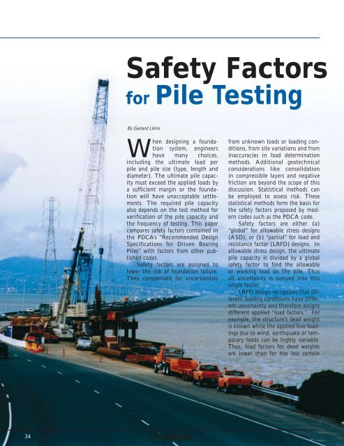
<strong>Safety</strong> <strong>Factors</strong>for <strong>Pile</strong> TestingBy Garland LikinsWhen designing a foundationsystem, engineershave many choices,including the ultimate load perpile and pile size (type, length anddiameter). The ultimate pile capacitymust exceed the applied loads bya sufficient margin or the foundationwill have unacceptable settlements.The required pile capacityalso depends on the test method forverification of the pile capacity andthe frequency of testing. This papercompares safety factors contained inthe PDCA’s “Recommended DesignSpecifications for Driven Bearing<strong>Pile</strong>s” with factors from other publishedcodes.<strong>Safety</strong> factors are assigned tolower the risk of foundation failure.They compensate for uncertaintiesfrom unknown loads or loading conditions,from site variations and frominaccuracies in load determinationmethods. Additional geotechnicalconsiderations like consolidationin compressible layers and negativefriction are beyond the scope of thisdiscussion. Statistical methods canbe employed to assess risk. Thesestatistical methods form the basis forthe safety factors proposed by moderncodes such as the PDCA code.<strong>Safety</strong> factors are either (a)“global” for allowable stress designs(ASD), or (b) “partial” for load andresistance factor (LRFD) designs. Inallowable stress design, the ultimatepile capacity is divided by a globalsafety factor to find the allowableor working load on the pile. Thusall uncertainty is lumped into thissingle factor.LRFD design recognizes that differentloading conditions have differentuncertainty and therefore assignsdifferent applied “load factors.” Forexample, the structure’s dead weightis known while the applied live loadingsdue to wind, earthquake or temporaryloads can be highly variable.Thus, load factors for dead weightsare lower than for the less certain34
live loads. LRFD methods assign differentstrength factors (often called“resistance factors” with values lessthan unity) which relate to the verificationprocedure reliability. The generalexpression for LRFD design is iQ i≤ kR kWhere iis the load factor forthe load Q iof the ith load type (e.g. 1might be 1.4 for the dead load Q 1,and 2might be 1.7 for the live loadQ 2), and is the resistance factorkfor the resistance R kfor the kth limitstate (e.g. might be 0.80 for a staticload test R on 1% of the piles). Inconcept, for a given set of load andresistance factors, an equivalentglobal safety factor can be calculatedfrom the load factor divided by theFORD PILEFOUNDATIONS, INC.PILE DRIVING - PILE LOAD TESTINGSTEEL SHEETING - HELICAL PIER UNDERPINNINGOffice and Yard: 4985 Euclid Road, Virginia Beach, Virginia 23462Mailing Address: P.O. Box 62364, Virginia Beach, Virginia 23466Telephone: (757) 497-3593 Fax: (757) 497-0031E-mail: piledriver@msn.comresistance factor (e.g. in the aboveexamples, the equivalent globalsafety factor is 1.94 for a 50% deadload situation). Further mentionof LRFD in this article will usecomputed equivalent global factors.The risk of foundation failuresmakes capacity evaluation necessary.Logically, less testing increases therisk of a failed foundation, whilemore testing reduces risk. Similarly,more accurate test methods reducerisk, while less accurate methodsincrease risk. The goal is anacceptably low probability of failure.<strong>Pile</strong>s can potentially fail either dueto structural failure or geotechnicalfailure (e.g. soil strength). Generally,driven piles rarely fail structurally(drilled or augered piles have a higherprobability of structural failure andthus usually have higher associatedsafety factors, or lower factors onthe structural strength conditions).Static Load Testing hastraditionally been the standard forevaluating soil strength and ultimatepile capacity. Prior to about 1970, pileswere loaded using a slow maintainedload procedure over several days totwice the design load, as specifiedin ASTM D1143. Generally, onlyone static test was performed persite and these “proof tests” rarelyInstalling Driven <strong>Pile</strong>s in Tidewater andThroughout the Southeast for 56 YearsMARINE CONTRACTINGCORPORATIONMARINE CONSTRUCTION AND DEMOLITIONPILE DRIVING AND DREDGINGOffice: 1397 A Air Rail Ave, Virginia Beach, Virginia 23455Mailing Address: P.O. Box 5525, Virginia Beach, Virginia 23471Telephone: (757) 460-4666 Fax: (757) 363-9647E-mail: mccorp@infi.netProviding a Full Range ofMarine Construction Services for 23 Years36
<strong>Pile</strong> Testing InstrumentationGeokon, Incorporated manufactures a fullrange of geotechnical instrumentationsuitable for monitoring loads, strains anddeformation in piles.Geokon instrumentation employsvibrating wire technology that providesmeasurable, long-term advantages:Cut or splice cables without adverseeffect on readingsProven long-term stabilityRemote datalogging possibleDSP, noise-free dataGeokon, Incorporated48 Spencer StreetLebanon, NH 03766USA1 • 603 • 448 • 15621 • 603 • 448 • 3216info@geokon.comwww.geokon.commethod (e.g. static load test) witha conservative failure definition,the safety factor can be significantlyreduced because the risk is reduced.The offset yield line criteria recommendedby the PDCA code is amongthe most conservative of failure criteriaand thus justifies lower safetyfactors.The PDCA code awards lowersafety factors for testing more piles,because the uncertainty is reduced.For testing only 0.5% of the piles, asafety factor of 2.0 is suggested, whileif 5% of the piles are tested, then thesafety factor can be reduced to 1.65.<strong>Pile</strong>s are selected so site variability isadequately addressed, and adequatehammer performance is periodicallyverified. Lower safety factors meansthe pile load can be increased, resultingin fewer piles, or that the drivingcriteria can be relaxed, thus reducingproduction pile installation timeand costs. The extra testing costs aremore than compensated by reducedfoundation costs.Dynamic <strong>Pile</strong> Testing is a routinepile capacity evaluation method.Dynamic testing requires measuringpile force and velocity duringhammer impact and subjecting thisdata to a signal matching analysisto determine the soil behavior.Extensive correlations between staticand dynamic testing have verifiedthe method’s reliability. After correlatingthe static and dynamic tests,the PDCA code allows substitutionof three dynamic tests for one statictest in determining the quantity offurther testing. Thus, with at leastone successful correlation, then thePDCA suggested 5% static testingcan be translated into testing 15%of the piles dynamically, for thesame suggested safety factor of 1.65.The large number of tests allows sitevariability and hammer performanceconsistency to be properly assessed.In many cases, dynamic pile testinghas completely replaced statictesting. In this case, no site-specificcorrelation is established and thusthere is a higher risk, since the correlationdepends upon past experienceof the signal matching analysisaccuracy. This extra risk requiresan increased safety factor comparedwith static testing methods. In thiscase, the safety factor can vary from2.1 with only 2% of the piles testeddynamically down to 1.9 when atleast 10% of the piles are testeddynamically.To obtain a reliable ultimatecapacity from dynamic pile testing,some very basic guidelines must befollowed. The hammer input must besufficiently large to produce a minimumset per blow so the soil is loadedplastically and thus mobilizes thefull soil strength. In cases where theset per blow is very small (e.g. large“blow count”), the dynamic pile testwill only activate a portion of the fullsoil strength and thus will under-predictthe true ultimate capacity (thisis analogous to a “static proof test”),so the result is conservative. Finally,the pile capacity often changeswith time after installation (usuallyincreases due to “setup,” although insome cases reduction due to “relaxation”are found). To measure timedependent capacity effects, the pileshould be tested by restrike after anappropriate waiting time. Restriketests are recommended standardpractice for capacity evaluation bydynamic pile testing.Dynamic testing provides otherbenefits. Dynamic pile testing providesvaluable additional informationon driving stresses which, if toolarge, can result in pile damage. <strong>Pile</strong>integrity can be evaluated dynamicallyfor both location and extentof damage, if any. Proper hammerperformance is extremely importantfor driven piles because engineersrely on the blow count (or set perblow) as a driving criteria for pileacceptance, thus implicitly assumingthat the hammer is performingproperly. By monitoring periodicallythroughout larger projects, it can beassured that the hammer is performingproperly and consistently duringthe entire project so that the sameinitial driving criteria can be used forall piles with confidence. Periodictesting can check site variability andinvestigate the cause of piles that aretoo short or too long or that haveunusual blow count records to determineif the cause is the hammer orthe pile or the soil. These guidelines38
for checking site variability and periodichammer verifications are mentionedin the PDCA code.Wave Equation Analysis isa computer simulation of the piledriving process. A numerical modelis constructed for the hammer, forthe pile, and for the soil. Numerousassumptions are made, such as hammerperformance and soil responsebehavior. Assumed ultimate capacitiesare entered, a one dimensionalwave propagation analysis is made,and the resulting blow counts arepredicted. A series of assumed resistancesand associated predicted blowcounts produce a “bearing graph” toestablish a suggested driving criteria.However, because of the increaseduncertainty associated with theassumptions, the risk is increased andthus the safety factor in the PDCAcode is suggested as 2.5.Dynamic Formula were developedover 100 years ago to estimatepile capacity by simple energy considerations.Some engineers still usethem today to make a preliminaryselection of hammer size. However,these methods are very simplistic.Numerous studies have concludedthat their prediction accuracy is poorand, to minimize risk, large safetyfactors are necessary. The standardENR formula, for example, has abuilt-in safety factor of 6. Recentstudies have shown that the Gatesformula is statistically the best forprediction. The Gates formula is theonly formula currently recognizedby the PDCA, AASHTO, and theFHWA (although FHWA stronglyrecommends that dynamic formulabe replaced by wave equation analysis).Since accuracy is relatively poorand risk increased, the recommendedsafety factor by PDCA for the Gatesformula is 3.5.Static Analysis estimates pilecapacity from soil strength estimatesobtained from site soil investigations.Numerous correlations and empiricalcorrection factors for soil strengthwere developed for SPT, CPT, orother soil sampling tools. However,there generally is considerable scatterof strength prediction results andlocal experience does not transfer todiffering conditions or differing samplingmethods. Numerous predictionevents have demonstrated that suchpredictions are generally highly inaccurate.Because of large inherent riskdue to poor prediction accuracy, thePDCA code requires a safety factorof 3.5 for piles installed to a staticanalysis criteria only for an acceptablelevel of risk.Comparison of the PDCA Codewith Other Codes is summarized inthe accompanying table and providesan interesting platform for discussion.The PDCA code origin startedwith the AASHTO Standard ASDcode from 1992.AASHTO (American <strong>Association</strong>of State Highway andTransportation Officials) representsthe 50 state highway departmentsplus the FHWA. Subsequently,AASHTO is moving toward LRFDCost Effective Timber <strong>Pile</strong>Foundation SolutionsThe low cost piling solution forFoundation and Marine piling.Design capacities to 75 tons.Technical seminars available.Design information available.From a natural, renewableresource.For more information contact:TIMBERPILINGCOUNCILFOUNDATION & MARINE PILING800-410-2070 pstFax: 206-275-4755www.awpi.orginfo@timberpilingcouncil.org40
ut the result is still under development. Because of similaritiesof origin, factors for static analysis and dynamicformula are identical to the PDCA code. AASHTOrecognizes that wave equation analysis is more reliablethan dynamic formula so the safety factor is setat 2.75. Dynamic testing does not specifically mentionsignal matching and thus may partially account forthe relatively high factor 2.25 for dynamic testing. Statictesting alone has the traditional standard factor of 2.0.Testing both statically and dynamically results in a lowersafety factor of 1.9. Generally, the AASHTO code doesnot address the amount of testing to be performed.IBC 2000, from the International Building Code, isan effort of the three USA regional building codes to forma single national code. The foundation section comesoriginally from the Southern Building Code which has itsbase from the 1940s with an update in 1982 to cover a few“new technology” items missing from the original code(e.g. prestressed piles, et al), but nothing new relating tosafety factors. The IBC did provides for dynamic pile testing(as per ASTM D4945) as a new inclusion of this newcode. This SBC code is obviously the oldest and generallyreflects older practice requirements. For piles withdesign loads under 40 tons, capacity is determined by “anapproved driving formula” or by static analysis, with noload testing required. The static analysis uses either a soilsinvestigation or a safety factor of 6 referenced to a chartOVERSTOCKED INVENTORY FOR SALEAVERAGEFOOTAGE O.D. LENGTHS15,000 3 1/2" 0.375 Wall 12.52 # 30 FT70,000 5" 0.478 Wall 23.08 # 44/45 FT13,000 7" 0.317 Wall 22.63 # 43 FT40,000 7" 0.362 Wall 25.66 # 42 FT50,000 7" 0.408 Wall 28.72 # 44/45 FT9,000 7 5/8" 0.328 Wall 25.56 # 45 FT100,000 7 5/8" 0.375 Wall 29.04 # 43/44 FT20,000 7 5/8" 0.430 Wall 33.04 # 42 FT8,500 9 5/8" 0.352 Wall 34.86 # 43 FT10,000 9 5/8" 0.395 Wall 38.94 # 40 FT12,000 9 5/8" 0.472 Wall 46.16 # 44 FT90,000 9 7/8" 0.625 Wall 61.74 # 44/45 FT5,000 10 3/4" 0.500 Wall 54.74 # 44 FT5,000 10 3/4" 0.545 Wall 59.40 # 44 FT20,000” 10 3/4" 0.562 Wall 61.21 # 44 FT12,000” 10 3/4" 0.595 Wall 64.49 # 44 FT6,000” 11 7/8" 0.582 Wall 70.13 # 41 FTof conservative soil strengths.For loads of 40 tons or higher,wave equation analysis is specifiedto estimate the driving criteria,and the load is to be verifiedby either static or dynamic testing(dynamic testing in ASTMD4945 indirectly implies at leastone correlating static test).In contrast to IBC 2000, theAustralian Code AS2159-1995is perhaps one of the most progressivein the world. AS2159is an LRFD code and the globalfactors shown here for comparisonare computed from an equalweighting of live and dead loads(having 1.5 and 1.25 load factorsrespectively). The rangeof safety factors in the code isgiven with some guidance by thecode. The dynamic formula factorsare to be applied to sandysoils only; dynamic formula areprohibited for clay soils. <strong>Factors</strong>for static analysis are based onthe soil exploration method(e.g. SPT or CPT; CPT methodsare given higher confidenceand thus lower safety factors).The dynamic testing factorsrequire signal matching. Lowersafety factors for dynamic testingrequire at least 15% of the pilesto be dynamically tested (and also comprehensive siteinvestigations and careful construction control), whilehigher factors result when less than 3% of the piles aredynamically tested. The lowest static testing safety factorscome from statically testing more than 3% of the piles,while higher factors apply when less than 1% of the pilesare statically tested.The ASCE 20-96 is the Standard Guidelines for theStroer & Graff, Inc.PILEDRIVING CONTRACTORSSaginaw Pipe Co., Inc.46 North Main Street, Kingwood, Tx 77339(800) 571-7473 | (281) 361-5915 | (281) 361-6025 faxContact Ray Vetters, Dennis Ince, Bill Walker1830 Phillips LaneAntioch, California94509-7306(925) 778-0200(925) 778-6766 FAX42
Design and Installation of <strong>Pile</strong>Foundations. This code is quitedifferent from others in that thesafety factor is defined by threeparts (capacity determinationmethod, design axial load levels,and structural pile type). Thecapacity determination methodis the only common criteriawith other codes. The latter twocriteria have come under somerecent criticism (“ProposedOverhaul of Deep FoundationProvisions of the InternationalBuilding Code” by Len Cobb,presented at the ASCE Geo-Institute Deep Foundations 2002Conference, Feb 2002). Becauseof more structural uncertainty,this code requires significantlyhigher safety factors for nondrivenpiles. Determination ofcapacity solely on static analysisis not permitted. Except forlightly loaded piles, dynamicformula are not recommendedand no factors are even suggested(factors for lightly loadedpiles are unrealistically small forthe associated risk). The factorsfor dynamic and static testingare generally similar to PDCAvalues for lower pile loads, butthe factors are higher than thePDCA values for piles with design loads of 40 tons ormore. (This code is currently in a revision process andsafety factors are likely to be reduced for the higher loadcases).As a common practice, static analysis methods aregenerally only used to estimate pile lengths in the designprocess. Rarely are pile installations governed by thismethod, so whether a code has a factor or not for staticanalysis is almost a non-issue. Dynamic formula are alsodecreasing in usage. They remain mainly a tool for preliminaryhammer selection. In most cases, actual use ofdynamic formula to govern pile installation are perhapslimited to light design loads. From a practical view, awave equation analysis is almost as fast and simple asa dynamic formula. Generally, some other more precisemethod (wave equation, dynamic testing, or static testing)is also specified on most projects, particularly projectswith design loads above 40 tons, so the lower safetyfactor and improved reliability of the more accuratemethods would then govern the project anyway.In summary, keeping the risk of foundation failurebelow an acceptable level is the goal for any foundation.To accomplish this, safety factors are applied tothe ultimate pile capacity to calculate an acceptabledesign or working load for the piles. The risk of failurecan be reduced by testing more piles, or using evaluationmethods that are more accurate. A reduced risk of failurejustifies lower safety factors. The safety factors recommendedby several newer codes generally give a rangeof safety factors depending on the type and amount oftesting performed on site, and result in factors less thanthe traditional factor of 2.0. These more modern testingmethods, combined with a higher frequency of testingand the resulting lower safety factors, can reduce thetotal foundation costs. ▼LOGISTICS PROFESSIONALSServing All PointsService is Our Business!Power Only • FB • SD • Heavy Haul • V • HazmatPhone: 985-893-7878 or 800-256-2185Fax: 985-893-522243