Driven Piles are Tested Piles! - Pile Driving Contractors Association
Driven Piles are Tested Piles! - Pile Driving Contractors Association
Driven Piles are Tested Piles! - Pile Driving Contractors Association
- No tags were found...

Create successful ePaper yourself
Turn your PDF publications into a flip-book with our unique Google optimized e-Paper software.
A Presentation of
From a stick in the mudto a technologicallyproven tool, driven piles<strong>are</strong> as old as history andas new as tomorrow!
Archeologists have determined that driven piles have been used since Neolithictimes. The lake dwellers of what is now Switzerland, northern Italy, Austria andeastern France constructed their villages on driven pile supported platforms as adefensive measure. The builders of the ancient village discovered at Wangen,Switzerland utilized 50,000 piles in the construction of their village. Primitivecivilizations around the world have used driven piles and poles to support theirhomes in water and in flood prone <strong>are</strong>as. Predecessors to the Aztecs in the MexicoCity <strong>are</strong>a built their sites on lakes in the <strong>are</strong>a on pile supported mats topped withsoil called “Chinampas” or on <strong>are</strong>as contained by driven piles and filled with soiland stone. Ancient tribes in the Java Sea <strong>are</strong>a built stilted villages. AncientChinese engineers built bridges on driven piles.
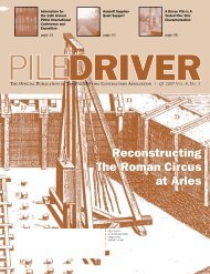
The Greeks and Romans utilized driven piles to support bridges, aqueducts and otherstructures in poor soils, many of which <strong>are</strong> in use today. Bridges crossing the majorrivers of Europe were constructed by the Romans to maintain control of their empire.The Roman Circus at Arles in France was founded on driven piles and in modernarcheological excavations found to be in good condition and to have supported theirloads for about a thousand years until the structure fell into disuse. Amsterdam wasfounded in the early 1300’s. During a major growth period in the 1600’s the diggingof canals created a hundred man-made islands for housing. These residential <strong>are</strong>aswere connected by 300 pile supported bridges. Even today, most of the city is pilesupported. Other examples of historical use of driven piles abound throughoutEurope.Roman AqueductModel of <strong>Pile</strong> Foundation, Circus of Arles
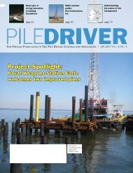
A modern barge mounted rig utilizing an accurately placed template.
Today owners, engineers andcontractors have a whole arsenalof modern technology and toolsavailable to them to assist inproviding efficient and economicaldeep foundation solutions.
From site investigation to design, better understandingof soil properties and new computerized tools <strong>are</strong>available to engineers. Installation problems,equipment capabilities and load carryingcharacteristics of various pile types <strong>are</strong> able to beanticipated with a high degree of accuracy even beforethe design is completed. Better understanding of theperformance and strength of materials, in conjunctionwith new and stronger materials, and workingtogether with modern codes, permit greaterefficiencies in the selection of pile types.
Modern equipment can be employed by contractors toensure safe, quick and adequate installation of drivenpiles. Global Positioning Systems (GPS) aid in surveyand accurate layout of pile locations. New hammers<strong>are</strong> capable of energy adjustments and monitoring toprovide the required hammer performance whileprotecting the piles from damage. Instruments can beused during testing and installation to confirm thedesign and pile load capabilities. Testing techniques<strong>are</strong> also available to check the performance ofpreviously driven piles to comp<strong>are</strong> them with therequirements of the specifications.
A driven pile is atested pile!Definitions and comparison toother deep foundation elements.
A pile can be defined as astructural column installed in earthand provided to offer support or toresist forces.
A <strong>Driven</strong> <strong>Pile</strong> is a relatively long,slender column, provided to offersupport or to resist forces, made ofpreformed material, and having apredetermined shape and size that canbe physically inspected prior to, andduring installation, and which isinstalled by impact hammering,vibrating, or pushing into the earth.
A Drilled <strong>Pile</strong> is made of concrete or groutand cast or poured, in a plastic state, intoa drilled hole in the earth. Augercast,Drilled Shafts, Drilled Cast-in-Place and,their variations <strong>are</strong> all forms of drilledpiles. Completed drilled piles cannot beeasily inspected after installation and canbe difficult to install in very soft or loosesoils, wet, and marine conditions.
A Drilled <strong>Pile</strong> removes soil from theground and the resulting round hole isfilled with concrete or grout.A <strong>Driven</strong> <strong>Pile</strong> is installed as a whole,rigid, structural member into theground from the surface. <strong>Driven</strong> <strong><strong>Pile</strong>s</strong><strong>are</strong> said to be either “displacement” or“non-displacement” piles.
Displacement <strong><strong>Pile</strong>s</strong> <strong>are</strong> considered solidshapes that during installation,displace the soil laterally.Non-displacement <strong><strong>Pile</strong>s</strong> <strong>are</strong> of hollowor “outline” shape and displace little orno soil during installation.
Basic <strong>Pile</strong> InstallationTechniques(driven vs. drilling)
Drilled <strong><strong>Pile</strong>s</strong> <strong>are</strong>installed by drillinga hole in the soil,typically using anauger. Grout orconcrete is placed inthe hole to form thepile.
Augered Cast-in-Place <strong>Pile</strong> Installation
Drilled Shaft Installation
<strong>Driven</strong> piles <strong>are</strong> installed using an impacthammer, vibro driver or hydraulic press andperformance is routinely monitored duringoperation. Modern driven pile installationequipment is capable of providing consistent,known energy that can be easily measuredduring operation. Advancement of the pile intothe earth can be monitored and recorded forfuture study and comparison to other tested andinstalled piles.
A <strong>Driven</strong> <strong>Pile</strong> is onewhich is ofpredetermined solidmaterial, shape andsize, that can beseen, felt, and,inspected prior toinstallation andwhich is installed bydriving or pushinginto the earth.
Types of <strong>Driven</strong> <strong><strong>Pile</strong>s</strong><strong>Driven</strong> <strong><strong>Pile</strong>s</strong> can be classified bytheir structural use (designfunction) or, by the materialsfrom which they <strong>are</strong> made.
<strong><strong>Pile</strong>s</strong> classed by structural use will fall into oneof the following groups or combinations of thesegroups.•Resisting Vertical Compressive Forces•Resisting Lateral Forces•Resisting Tension Forces
Resisting VerticalCompressiveForces - where theanticipated supportrequires resistance tovertical compressiveloads, such as forbuildings, bridges,docks, towers, tanks,etc.
Resisting Lateral Forces - where the forces tobe supported <strong>are</strong> from the side or laterally, as insheet piles, mooring and fender piles and othersimilar situations.
Resisting Tension Forces - counteracting wind oroverturn loads (guyed anchors for towers, signs);opposing buoyancy and floatation forces as intanks, pools, mooring pile, etc.; load balance infooting design limitations, etc.
<strong><strong>Pile</strong>s</strong> classed by the materialsfrom which they <strong>are</strong> made willbe one of the following orcombinations of these:
• Timber• Concrete (Precast & Precast-prestressed).• Pipe <strong><strong>Pile</strong>s</strong> (Open-end & Closed-endconcrete filled).• Structural Steel & Aluminum Shapes ("H”sections, sheets, combo piles).• Synthetic materials (fiberglass, polymers,vinyl, etc.)
<strong>Driven</strong> piles can be either displacementpiles, i.e. of solid shape or, nondisplacement,i.e. hollow or of outlineshape. Sheet piles <strong>are</strong> specialized types ofnon-displacement piles formed in sheetsand having connections on the edges topermit interlocking with adjacent piles.Composites and combinations of these <strong>are</strong>also used.
Timber <strong><strong>Pile</strong>s</strong>Timber piles <strong>are</strong> made from the trunks of tall, straight trees.The more typical species <strong>are</strong> conifers such as SouthernYellow Pine and Douglas Fir. Untreated timber piles <strong>are</strong>suitable for temporary situations and in situations wherethe top of the pile will always be in soil below groundwaterlevel. All permanent timber piles driven in marineenvironments and where the butt (upper end) will be abovegroundwater levels require a preservative treatment to resistrot and insect and marine borer attack. Combinations ofuntreated timber topped by a metal shell filled with concrete<strong>are</strong> in common use in some <strong>are</strong>as of the U.S. where groundwater is found to be within approximately 10 feet of thesurface.
Timber <strong><strong>Pile</strong>s</strong> (Displacement <strong>Pile</strong>)
Timber <strong><strong>Pile</strong>s</strong> (Displacement <strong>Pile</strong>)
Timber <strong><strong>Pile</strong>s</strong> (Displacement <strong>Pile</strong>)
Combination <strong><strong>Pile</strong>s</strong>(Untreated timber with a concrete filled metal shell)
Concrete <strong><strong>Pile</strong>s</strong>Concrete piles (Precast & Precast-Prestressed) <strong>are</strong> commonlymanufactured in solid or hollow form and, squ<strong>are</strong>, octagonalor round cross section. Modern manufacturing employs atechnique of pre-stressing which increases resistance tobending and reduces the amount of internal steelreinforcement required. This process involves the placing ofspecial cables in the form used the make the piles. The cables<strong>are</strong> pre-tensioned before the placement of the concrete and,after the concrete begins curing, the tension is released. Thishas the effect of providing internal compressive forces in thepile and, increasing stiffness and toughness of the pile,permitting longer lengths and harder driving. Because of theinherent resistance to corrosion, concrete piles provide a goodmaterial for marine applications.
Solid Precast Concrete (Displacement <strong>Pile</strong>)
Solid Precast Concrete (Displacement <strong>Pile</strong>)
Solid Precast Concrete (Displacement <strong>Pile</strong>)
Concrete Cylinder <strong>Pile</strong> (Non-Displacement)
Concrete Cylinder <strong>Pile</strong> (Non-Displacement)
Combination <strong><strong>Pile</strong>s</strong>(Tapered Concrete & Pipe <strong><strong>Pile</strong>s</strong>)
Combination <strong><strong>Pile</strong>s</strong>(Precast Concrete & “H” <strong>Pile</strong> Points)
Pipe <strong><strong>Pile</strong>s</strong>Pipe piles made of steel can be of varying diameters fromless than 6 inches to as large as 8 feet or more. Thestrength of the pipe pile is largely determined by thethickness of the wall and the strength of the steel. Insituations where additional strength or resistance tobending is required concrete is placed in the pile afterdriving. Pipe piles can be driven either with a steel platewelded on the bottom (closed-end) as a displacement pileor open-ended as a non-displacement pile. Pipe piles canbe easily spliced to extend the piles when required, eitherby welding or through the use of mechanical connectors.
Pipe piles can be coated to provide protection fromcorrosion where required. A unique form of the pipepile is the tapered steel pile, driven with a closed end andhaving increasing diameters from the tip. This wedgeshape provides additional load capacity in someapplications and can be increased in length by splicing asection of uniform diameter pipe pile to the top.
Closed-End Pipe <strong>Pile</strong> (Displacement <strong>Pile</strong>)
Closed End Pipe (Displacement <strong>Pile</strong>)
Closed-End Pipe <strong>Pile</strong> (Displacement <strong>Pile</strong>)
Closed-End Pipe <strong>Pile</strong> (Displacement <strong>Pile</strong>)(with corrosion protection coating)
Closed-End Pipe <strong>Pile</strong> (Displacement <strong>Pile</strong>)(with Spin Fins© for added tension capacity)
Open End Pipe (Non-Displacement <strong>Pile</strong>)
Open End Pipe (Non-Displacement <strong>Pile</strong>)
Open End Pipe (Non-Displacement <strong>Pile</strong>)
Closed-End Pipe <strong>Pile</strong> (Displacement <strong>Pile</strong>)(Tapered, fluted steel piles)
Structural Shapes - Steel & Aluminum<strong><strong>Pile</strong>s</strong> have been made from structural steel shapes for over125 years and <strong>are</strong> commonly rolled steel formed into an“H” cross section shape. “I” beams and fabrications ofrailroad rail have also been used. Structural steel piles <strong>are</strong>,non displacement piles and have an advantage of highstrength to weight ratio, great bending resistance, ease ofsplicing for longer lengths and by their nature, lower ratesof soil displacement to affect adjacent <strong>are</strong>as. Steel is themost common material used for sheet piles and in someinstances <strong>are</strong> combined with other shapes to form “combopiles” for use in applications requiring additional bendingstrength.
“H” <strong><strong>Pile</strong>s</strong> (Non-Displacement <strong>Pile</strong>)
“H” <strong><strong>Pile</strong>s</strong> (Non-Displacement <strong>Pile</strong>)(Extending “H” piles by welding)
“H” <strong><strong>Pile</strong>s</strong> (Non-Displacement <strong>Pile</strong>)
“I ” Beam <strong><strong>Pile</strong>s</strong> (Non-Displacement <strong>Pile</strong>)
Sheet <strong><strong>Pile</strong>s</strong>Steel sheet piles in a “Z”, arched or, flat cross section <strong>are</strong>other steel piles in common use. Sheet <strong><strong>Pile</strong>s</strong> <strong>are</strong> unique inthat they <strong>are</strong> designed to be joined with adjacent piles bythe use of integral interlocks. Galvanized light gauge steeland Aluminum sheet piles <strong>are</strong> gaining acceptance forlightly loaded sheeting applications and offer theadvantage of corrosion resistance in bulkheadapplications.
Steel Sheet <strong><strong>Pile</strong>s</strong>
Steel Sheet <strong><strong>Pile</strong>s</strong>
Steel Sheet <strong><strong>Pile</strong>s</strong>
Combination (Combo) <strong><strong>Pile</strong>s</strong>(Steel Sheet<strong><strong>Pile</strong>s</strong> & WFBeams)
Synthetic MaterialsVinyl, Fiberglass and, polymers <strong>are</strong> a few of therecently used materials for piles, particularly in specialapplications. Vinyl sheet piles <strong>are</strong> becoming acommon application where aesthetics <strong>are</strong> importantand the lateral loads <strong>are</strong> not great. Examples of this<strong>are</strong> found in residential waterfront bulkheads wherean owner can have a clean white wall at the watersedge. Fiberglass reinforced plastic (or polymer) piles<strong>are</strong> used in applications where resiliency or springaction is required, such as vessel mooring or fenderpiles along a dock. Other materials and applications<strong>are</strong> employed when special concerns require them.
Vinyl Sheet <strong><strong>Pile</strong>s</strong>
<strong>Pile</strong> Installation EquipmentThe primary tools used in the actual driving(installing) of piles <strong>are</strong>•Impact Hammers,•Vibratory Driver / Extractors•Special Hydraulic Presses•Supporting Equipment - power sources,hoisting & material handling equipment, etc.
Impact HammersIn the simplest sense, Impact Hammers <strong>are</strong> those whichadvance the pile in the soil by the raising of a weight (orram) which is then allowed to fall or, is accelerateddownward to strike the pile and “drive” it downward. Inuse all Impact Hammers <strong>are</strong> provided with an attachment(called a drive cap, bonnet, helmet or sometimes a hood)between the top of the pile and the lower end or base of thehammer. The purpose of this attachment is to adapt theend of the pile to the base of the hammer, to maintainalignment of the pile to the hammer and lead guides and,to protect the top of the pile from excessive impact shockforces. Most caps incorporate a cushioning element to aidin reducing shock loads to the hammer and the pile.
Types of Impact HammersImpact Hammers <strong>are</strong> identified bytheir method of operation or themotive force employed. They <strong>are</strong>generally identified as:•Drop Hammers•Air or Steam Hammers•Diesel Hammers•Hydraulic Impact Hammers
Drop HammersDrop Hammers <strong>are</strong> the simplest and oldest type ofImpact Hammer. In this style of hammer, an outsidelifting force (a winch) raises a weight and then releasesit to free fall, impacting the drive cap or follow blockresting on the top of the pile, driving the pile into theground. The mass of the weight or ram is usuallyknown and, if the height of the drop is regulated, thedriving energy (kinetic energy) can be determined andregulated. Frictional losses, especially in the winch,diminish substantially the actual energy output of thistype hammer. Though not often used, in someapplications, the techniques of old <strong>are</strong> the economicaland practical solution to some of today’s foundationproblems.
Drop Hammer(With followblock / drivecap on pile)
Air (or Steam) HammersThese Hammers <strong>are</strong> operated by compressed air or steam providedfrom an air compressor or steam boiler. This motive power is used toraise the ram to a predetermined height and, through automatic valveaction, the motive power is shut off. The ram coasts upward somedistance, and then, is allowed to fall under the force of gravity. As theram reaches the limit of downward travel and strikes the top of thedrive cap, the pile is driven downward, and the valve actuates, movingthe ram upward to start the process over.In some styles of hammers, additional air (or steam) is introduced intothe hammer at the top of the stroke to accelerate the downward travelof the ram. These <strong>are</strong> referred to as double acting or differentialhammers.
Air (or Steam) Hammers
Air (or Steam) Hammers
Diesel HammersDiesel Hammers operate as single cylinder, internal combustion dieselengines. A mixture of atomized diesel fuel and air <strong>are</strong> ignited bycompression caused by the falling ram. The resulting combustioncauses the ram to travel upward. The height of the ram's stroke isdetermined by the amount of diesel fuel used in combustion and by soilresistance. When the ram reaches its maximum stroke height, gravitythen sends the ram downward. As the ram travels downward fresh airand fuel <strong>are</strong> compressed in the combustion chamber by the ram'sdownward fall. When the ram reaches the bottom of the stroke itimpacts an anvil, driving the pile downward and simultaneouslyigniting the fuel to start the process over again. Some diesel hammersalso incorporate a closed, air filed chamber at the top of the hammerwhere the air is compressed by the ram’s upward travel, and ultimatelyaccelerates the ram downward for extra energy. This type of dieselhammer is said to be double acting, and operates at greater blows perminute.
Diesel Hammers
Diesel Hammers
Hydraulic Impact HammersHydraulic impact hammers employ a hydraulic power-pack,essentially a large engine driven pump system, which pumps specialoil under high pressure, through hoses connected to the hammer.The hammer consists of a ram/piston that is forced upward by thepressure of the oil. As the ram approaches the predetermineduppermost travel, automatic valve actuation causes a rapid release ofpressure, allowing the ram to coast slightly before falling, under theforce of gravity. Double acting hydraulic hammers utilize hydraulicpressure above the ram to accelerate the downward movement of theram, increasing the driving force and speed of operation. Hydraulichammers employ sophisticated control systems, providing variablespeed and stroke and therefore, precise regulation of energytransmission to the pile. Further, most hydraulic hammers utilizebuilt-in monitoring devices to record the particulars of the drivingoperation - rate of penetration, frequency and energy of the blows,etc.
Hydraulic Impact Hammers
Hydraulic Impact Hammers
Vibro Driver/ExtractorsVibro Drivers employ motor driven matched pairs of eccentricweights, revolving on horizontally mounted shafts, at relativelyhigh speeds in counter rotating directions. Because of thesynchronization and timing of the rotations, horizontal forces <strong>are</strong>cancelled and the resulting vertical forces provide a rapid verticalmotion to a rigidly clamped pile. The weight of the machine andthe rapid vertical motion provides the driving force to advance thepile in the soil. The motive power can be provided by electric, ormore typically hydraulic, motors mounted in the drive head.Auxiliary power packs provide energy to the on-board motors. Byits nature of operation, the Vibro Driver is most effective ingranular soils, and in driving non-displacement piles. Vibrodrivers <strong>are</strong> very effective in installing non-displacement piles -sheet piles, H piles, and open pipe piles. They <strong>are</strong> also usuallyvery effective in the extraction of all types of piles.
Vibro Driver/Extractors
Vibro Driver/Extractors
Hydraulic Press InstallersHydraulic Press installers utilize reactive resistance to anchor ahydraulically operated jacking system (rams) to push piles into theground. Reactive resistance can be from temporary weights oradjacent previously installed piles working in tension. HydraulicPresses utilize a power pack for motive power and <strong>are</strong> capable ofinstalling relatively long length piles in confined work <strong>are</strong>as.Additionally, this installation technique is very nearly vibration freeand can operate with little noise. These types of installers work mostefficiently with non-displacement piles such as sheet piles or openend pipe and H piles.
Hydraulic Press Installer
Hydraulic Press Installer
<strong>Pile</strong> Rigs & Configurations<strong>Pile</strong>driving rigs <strong>are</strong> configured in many different ways, dependingon the task requirements. However, there <strong>are</strong> common elementsin all configurations. Each must have a method of hoisting andpositioning the pile and a means of handling the installationequipment. In addition, the pile and the hammer or driver mustbe maintained in alignment during driving of the pile. A pile leador a template is utilized to maintain alignment and position of thepile and driver. Additionally, the complete apparatus must bepositioned for successive operations.Basically, there <strong>are</strong> three general scenarios for pile rigapplications - Land Based Rigs, Inland Marine Rigs, andOffshore Marine Rigs. Each of these will have common featuresand each can be found in modified arrangements as well.
Land Based RigsLand based rigs generally consist of a crane (either a crawler ortruck crane) mounted pile rig. Common arrangements can befixed lead or swinging lead types, with or without a template forguiding the piles during installation. A lead is a vertical structurewhose purpose is to align and guide the hammer and pile. Fixedleads <strong>are</strong> “fixed, or rigidly attached to the crane boom and oftenextend above the boom tip (cantilevered fixed lead). Fixed leadswhich do not extend above the boom tip <strong>are</strong> often referred to as“under slung leads”. This system uses a bottom brace or“spotter” to hold the lower end of the lead in position. A swinginglead is suspended from the boom tip, rather than being fixed to it,and may either be fixed at the bottom by use of stabbing points inthe ground or pinning to a template. Other specially designedarrangements <strong>are</strong> also utilized, including specifically designed pilerigs common in Europe and more recently seen in the US, withadaptations utilizing crawler excavator components.
Land Based RigsCantilevered Fixed Lead(With Fixed Bottom Brace)(With Spotter)
Land Based RigsUnder slung Swinging Lead(With Fixed Bottom Brace)(With Stabbing points)
Land Based RigsEuropean Style, Fixed Lead with Fixed Bottom Brace(<strong>Driving</strong> Aft Batter with Hydraulic Hammer)
Land Based RigsEuropean Style, Fixed Lead on Crawler Lower
Inland Marine RigsInland marine and shallow water applications generally require afloating platform to support a crane and the related toolsnecessary for pile driving. An alternative to this is the use of afixed platform such as a trestle. A variation of this is theutilization of the previously constructed work as a platform toadvance the project. As in land based work, the configuration ofthe rig can employ fixed leads, swinging leads and or a template.Sometimes contractors elect to employ the bell system typicallyused offshore. On occasion, because of limited access or otheroperating restraints, small, truckable, barges <strong>are</strong> attached togetherto form a larger work platform.
Inland Marine Rigs(Swinging Lead with Template)
Inland Marine Rigs(With Fixed Bottom Brace)(Swinging Lead with Template)
Inland Marine Rigs(<strong>Driving</strong> sheeting from sectional barges)
Inland Marine Rigs(Working from Trestle)
Inland Marine Rigs(Working from Trestle)
Offshore Marine RigsOffshore piledriving is generally in much deeper water depths thaninland marine work. The additional consideration of providing a workplatform suitable for open sea operations distinguishes this type work.The bell or, “offshore lead” used in deep water marine environments, is aspecial, relatively short, swinging lead having a “bell” guide at the lowerend to assist and hold alignment of the pile and hammer. It is a speciallydesigned structure used to handle the much larger equipment and pilesfound in these unique conditions. A template is commonly utilized tomaintain pile location in the unstable environment of the sea. Alignmentand placement of the pile and rig is frequently determined by GPS andsatellite navigation triangulation.
Offshore Marine Rigs(A <strong>Pile</strong> Supported Offshore Oil Platform)
Offshore Marine Rigs(Offshore <strong>Pile</strong> Rig Using a Template – With Hammers on Deck)
Offshore Marine Rigs(Hydraulic Offshore Hammers on Deck)
Offshore Marine Rigs(Hydraulic OffshoreHammer capable ofdriving underwater to deepdepths)
Offshore Marine Rigs(GPS Positioning for Offshore <strong>Pile</strong> Locations)
Quality Controls and ProductAssuranceWith the advent of increased materialstrengths and recent advances ininstallation equipment, greaterassurances of quality <strong>are</strong> also availableto owners, designers, and contractors.
Design StandardsBuilding and design codes <strong>are</strong>being modernized to takeadvantage of new technology andto meet ever increasing demandsof cost, efficiency, and facility ofinstallation. PDCA and itsmembers <strong>are</strong> active in theseefforts. The association has beeninstrumental in developing anddistributing the PDCARecommended DesignSpecification for Bearing <strong><strong>Pile</strong>s</strong>.
PDCA co-distributes FHWA’s National Highway Institute’s Design andConstruction of <strong>Driven</strong> <strong>Pile</strong> Foundations (a design guide and workshopmanual).
PDCA sponsors the dissemination of up-to-date information through theannual “Design & Installation of Cost-Efficient <strong>Driven</strong> <strong><strong>Pile</strong>s</strong> Conference”.
Material Standards & InspectionsModern standards recognize advancements inincreased strength and application of materials as wellas the development of new materials. <strong>Driven</strong> piles, bytheir nature, <strong>are</strong> manufactured prior to installation.This affords for visual inspection and testing to assurecompliance with the material standards andspecifications prior to installation.
Testing During DesignFrequently the first test made during the design of the foundation is thetaking and analysis of soil samples. Core samples <strong>are</strong> made to depthsdeeper than the deepest anticipated pile tip embedment. Analysis of thesoil properties can determine the size, type and depth of the pile.
<strong>Driven</strong> piles <strong>are</strong> often” proof tested” prior to driving permanent piles. Representativepiles <strong>are</strong> driven in simulation of job site conditions, and by monitoring andrecording, the effect of incrementally applied loads capacity of the piles can beconfirmed.
Dynamic testing of piles can be accomplished by monitoring instrumented pilesduring driving, both during the test pile phase, and during permanent pileinstallation to confirm bearing capacity and/or integrity.
Additionally, or in lieu of load testing, soil, pile, and hammer combinations can beanalyzed by computer driven wave equation analysis and fairly accurate predictionsof capacity and hammer performance provide confirmation of the design, drivabilityof the pile and the adequacy of the proposed hammer.
Installation Inspection &ConfirmationDuring driving of production piles, representative piles can be checked,blow by blow, by dynamic analysis of instrumented piles, verifyingintegrity of the pile, energy transfer, hammer performance and, pilecapacity at the time of driving.
Completed piles can be readily checked for integrity by use of “<strong>Pile</strong> IntegrityTesting”.
In cases where additional confirmation is desired, new load testing methods can beemployed to provide results quickly.
Logging of pile driving can monitor pile installation, blow by blow, and pile by pile,and can be accomplished manually or automatically, assuring that each pile is drivenas required for the design. The pile logs can be reviewed and readily comp<strong>are</strong>d withinformation developed during the test pile program.
Overview of the Process fromDesign to Finished Installation
PlanningOnce the owner defines the parameters of the use and type ofstructure, the design team goes to work planning the design.• Preliminary Analysis & Design (Engineering & GeotechnicalAnalysis) - This stage includes site and soil investigation and,preliminary calculations to determine the probable loadcapacities of various types of foundation elements.• Confirmation of Engineering & Design - Often times “Probe”,Indicator”, and/ or ”Test <strong><strong>Pile</strong>s</strong>” <strong>are</strong> driven at this stage and,"Load Tests” <strong>are</strong> performed to confirm the design parameters.(This stage also often occurs after Contract Award and priorto the start of production pile driving.)
Bidding & Contract AwardProject plans and specifications, once developed, <strong>are</strong> provided tothe bidders for the preparation of their estimates and bids.Contract Award is made on the basis of bidder responses, throughnegotiation, or a combination of these. Some design-buildprojects combine the design and construction responsibilities andthe winning bidder actively participates in the design process.Frequently, as a result of information learned during previoustesting and review, changes can be made to the project design toprovide more efficient and economical results, either throughmaterial and time savings, or through contractor valueengineering suggestions.
<strong>Pile</strong> InstallationClose coordination with the design team during installationensures a trouble free installation. Frequent review of jobprogress avoids problems and confirms that all piles <strong>are</strong> driven asintended and adequate for the project requirements. Questionablepiles can be evaluated and taken c<strong>are</strong> of in a timely manner toavoid unnecessary impact on overall progress.Unanticipated site condition problems can be solved through openand forthright communication between all parties concerned.
Quality ControlMaterial inspection reports give assurances of compliance to thespecifications and job requirements. A pile log of drivingprovides a record of progress and a check on the adequacy ofeach pile, affording the opportunity to take timely correctiveactions when necessary. Thus, every pile is a tested pile!On larger, and on more critical projects additional testing andmonitoring is undertaken; with additional dynamic or statictesting frequently being employed. When taken with theinformation developed during pile testing, compliance to thedesign is assured.
Completion & AcceptanceUpon completion of driving, a review of all inspection reports, andtest and driving records, should reveal all piles to have beeninstalled satisfactorily for the design.Should problems be revealed, modern testing/inspection tools willbe able to properly identify those problems so that appropriatecorrective actions can be undertaken.Once all <strong>are</strong> satisfied that all piles comply with contractrequirements, the only thing remaining is that the contractorbe paid! The owner having received with assurance, thefoundation he requires and, the piling contractor receiving notonly the satisfaction of a job done well, but the rewards for hisefforts!
AcknowledgementsAndSources of AdditionalInformationThis presentation is directed to thoseinterested in learning about driven piles andtheir benefits to solid foundation installationand design. It is intended to be anintroduction and guide to further study aboutdriven piles and their use and application.
The following PDCA Member Firms (and their contactemployees) have contributed significantly to the success of thisproject. We wish to acknowledge them and their assistance, forwithout their help the project would not have been possible.They <strong>are</strong> to be commended for their involvement and support ofPDCA and its programs.American <strong>Pile</strong>driving Equipment,Inc.John WhiteAmerican Wood Preservers Institute’sPole, Piling and Timber CouncilDean MatthewsBalfour Beatty Construction, Inc.Mark JohnnieBerminghammer Foundation EquipmentPatrick BerminghamCS Marine Constructors, Inc.Mark WeiszEd Waters & Sons Contracting Co., Inc.Van HoganGulf Coast Pre-Stress, Inc.Max J. WilliamsIHC Hydorhammer B.V.Geert Jonker
Johnson Bros. CorporationDan HickmanLiebherr Nenzing Crane Co.Wolfgang HerzogLink Belt Construction Equipment Co.Michael StewartMenck, GmbHDoug ScaggsMississippi Valley Equipment Co.Mike WhistlerPeirce Engineering, Inc.John J. PeircePeratrovich, Nottingham & Drage, Inc.Dennis Nottingham<strong>Pile</strong> Dynamics, Inc.Garland LikinsSkyline SteelJoao MartinsSpecialty Piling Systems, Inc.Steve Whitty
This presentation is a result of the efforts ofthe Communications Committee of the <strong>Pile</strong><strong>Driving</strong> <strong>Contractors</strong> <strong>Association</strong>:Van Hogan, ChairmanGarland Likins, MemberDoug Scaggs, MemberSteve Whitty, Member
The <strong>Pile</strong> <strong>Driving</strong> <strong>Contractors</strong> <strong>Association</strong> (PDCA) is an organizationof pile driving contractors that advocates the increased use of drivenpiles for deep foundations and earth retention systems. To do this, we:Promote the use of driven pile solutions in all cases where they <strong>are</strong>effective.Support educational programs for engineers on the design andefficiency of driven piles and for contractors on improvinginstallation procedures.Encourage and support research that will improve the reliability,usefulness, and cost effectiveness of driven piles.Give contractors a larger voice in establishing procedures andstandards for the installation and design of driven piles.
For membership information, additional information aboutsubject matter presented herein, or to contact any of thecontributors directly, please contact PDCA Headquarters:<strong>Pile</strong> <strong>Driving</strong> <strong>Contractors</strong> <strong>Association</strong>P. O. Box 66208Orange Park, FL 32065(888) 311-7322www.piledrivers.orgexecdir@piledrivers.org©2003 by PDCA – PDCA authorizes the duplication and copying of thismaterial for non-commercial, educational purposes, so long as it is notaltered, and all references to PDCA remain intact and <strong>are</strong> shown in allcopies and presentations.