DCS - Phocos.com
DCS - Phocos.com
DCS - Phocos.com

You also want an ePaper? Increase the reach of your titles
YUMPU automatically turns print PDFs into web optimized ePapers that Google loves.
<strong>DCS</strong><br />
CID No.181802011
CONTENTS<br />
1~8<br />
9~16<br />
17~24<br />
25~32<br />
33~40<br />
41~48
<strong>DCS</strong><br />
1
Abb. 1.2<br />
3<br />
Abb. 1.1
7 6 5 4 3 2 1<br />
7 6 5 4 3 2 1<br />
4<br />
JP1<br />
1.5V<br />
3.0V<br />
4.5V<br />
6.0V<br />
9.0V<br />
12.0V<br />
13.6V<br />
1.5V<br />
3.0V<br />
4.5V<br />
6.0V<br />
9.0V<br />
12.0V<br />
13.6V<br />
<strong>Phocos</strong> DC-L V-1-1
<strong>DCS</strong><br />
Linear DC/DC Convertor<br />
User Manual (English)<br />
9<br />
Dear customer,<br />
Thank you very much for<br />
buying a <strong>Phocos</strong> product.<br />
Please read the instruction<br />
carefully and thoroughly<br />
before using the product.
With your new <strong>DCS</strong> controller you own a state-of-the art device<br />
which was developed according to the latest available technical<br />
standards. It <strong>com</strong>es with a number of outstanding features,<br />
like:<br />
Operation of devices (e.g. radios) with different voltages<br />
in solar systems<br />
Selectable output voltages at the output terminals<br />
Electronic overload protection<br />
This manual gives important re<strong>com</strong>mendations for installing,<br />
using and programming as well as remedies in case of problems<br />
with the controller. Read it carefully in your own interest.<br />
Please take note of the safety and usage re<strong>com</strong>mendations<br />
at the end of this manual.<br />
Description of Functions<br />
The controller makes it possible to use electrical devices with<br />
a relatively low supply voltage. By setting the output voltage<br />
with jumpers (the output voltage is always lower than the<br />
input voltage), a wide variety of loads can be connected, for<br />
example devices that normally run on dry cell batteries ( 1.5,<br />
3, 4.5, 6, 9, 12, 13.6 Volt). In addition, the system is protected<br />
against overload.<br />
10
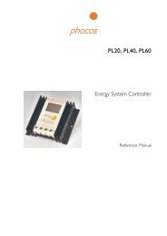
Mounting and Connecting<br />
General:<br />
When the batteries are not connected (Minus line), the Minus<br />
load output should be connected with Minus IN.<br />
Example:<br />
connecting in<br />
<strong>com</strong>bination with<br />
the CML, CA charge<br />
controllers (Fig. 1.1)<br />
Fig. 1.2<br />
11<br />
Fig.1.1<br />
Example:<br />
connecting in<br />
<strong>com</strong>bination with the<br />
CX charge controller<br />
(Fig. 1.2)
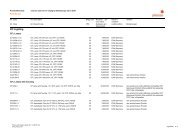
Setting of the Controller<br />
1. Location of jumpers on the circuit board:<br />
Jumper1<br />
7 6 5 4 3 2 1<br />
JP1<br />
1.5V<br />
3.0V<br />
4.5V<br />
6.0V<br />
9.0V<br />
12.0V<br />
13.6V<br />
2. Setting of the required output voltage<br />
(Jumper 1)<br />
Factory Setting<br />
12<br />
7 6 5 4 3 2 1<br />
1.5V<br />
3.0V<br />
4.5V<br />
6.0V<br />
9.0V<br />
12.0V<br />
13.6V<br />
<strong>Phocos</strong> DC-L V-1-1
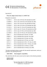
Mounting and Connecting<br />
(keep the right order in mind!)<br />
Set the jumpers in accordance with the intended use of the<br />
controller (see Setting of the controller in the previous chapter).<br />
Mount the controller to the wall.<br />
Connect the connection points of the output terminals with<br />
the device you want to use.<br />
Connect the input terminals of the <strong>DCS</strong> with the LOAD<br />
clamps of the upstream controller (ensure the correct<br />
polarity!).<br />
Complete the installation by connecting the sensor cable.<br />
Display Functions<br />
Red LED lights up :<br />
Current limitation is active.<br />
Yellow LED lights up:<br />
the controller is ready-tooperate.<br />
13
General Safety and Usage Re<strong>com</strong>mendations<br />
Safety Features<br />
The controller is not susceptible to overload.<br />
Re<strong>com</strong>mendations for Use<br />
The controller warms up during normal operation, depending<br />
on the connected loads. While in operation, the controller does<br />
not need any particular maintenance or service. Every now<br />
and then, remove dust with a dry tissue.<br />
Intended Use<br />
The <strong>DCS</strong> controller is intended only for downstream connection<br />
with established 12V photovoltaic systems (no shunt controller!).<br />
With systems in which the <strong>Phocos</strong> CML, CA or CX controllers<br />
are used, an optimal functioning of the controller is ensured.<br />
If you have any doubts, please contact your dealer or installer.<br />
Safety Re<strong>com</strong>mendations<br />
Batteries store a large amount of energy. Never short circuit<br />
a battery under any circumstances. We re<strong>com</strong>mend<br />
connecting a fuse (slow acting type) directly to the battery.<br />
Batteries can produce flammable gases. Avoid making sparks,<br />
14
using fire or any naked flame under any circumstances.<br />
Make sure that the battery room is sufficiently ventilated.<br />
Avoid touching or short circuiting wires or terminals. Be<br />
aware that the voltages on specific terminals or wires can<br />
be up to double the battery voltage. Use isolated tools,<br />
stand on dry ground and keep your hands dry.<br />
Keep children away from the batteries and the charge<br />
controller.<br />
Please observe the safety re<strong>com</strong>mendations of the battery<br />
manufacturer. If in doubt, consult your dealer or installer.<br />
Reverse polarity at the connector clamps should be avoided<br />
under all circumstances, as this can damage the device<br />
and/or the battery.<br />
This device has been developed and manufactured with<br />
care. As with any technical device, it has a limited life<br />
span. If batteries should be charged with the device, you<br />
should check regularly, if the voltage of the batteries falls<br />
within the permissible range. If no, disconnect the controller<br />
and other connected devices from the battery and contact<br />
your dealer or installer.<br />
Liability Exclusion<br />
The manufacturer shall not be liable for damages, especially on<br />
15
the battery, caused by use other than as intended or as<br />
mentioned in this manual or according to the re<strong>com</strong>mendations<br />
of the battery manufacturer. The manufacturer shall not be<br />
liable if there has been service or repair carried out by any<br />
unauthorized person, unusual use, wrong installation, or bad<br />
system design.<br />
Technical Data<br />
Subject to change without notice. Version:20080808<br />
Made in one of the following countries: China-Germany<br />
<strong>Phocos</strong> AG -Germany<br />
www.phocos.<strong>com</strong><br />
16
<strong>DCS</strong><br />
17
Fig.1.2<br />
19<br />
Fig.1.1
7 6 5 4 3 2 1<br />
JP1<br />
1.5V<br />
3.0V<br />
4.5V<br />
6.0V<br />
9.0V<br />
12.0V<br />
13.6V<br />
20<br />
7 6 5 4 3 2 1<br />
1.5V<br />
3.0V<br />
4.5V<br />
6.0V<br />
9.0V<br />
12.0V<br />
13.6V<br />
<strong>Phocos</strong> DC-L V-1-1
<strong>DCS</strong><br />
25
Sch 1.2<br />
27<br />
Sch. 1.1
7 6 5 4 3 2 1<br />
JP1<br />
1.5V<br />
3.0V<br />
4.5V<br />
6.0V<br />
9.0V<br />
12.0V<br />
13.6V<br />
28<br />
7 6 5 4 3 2 1<br />
1.5V<br />
3.0V<br />
4.5V<br />
6.0V<br />
9.0V<br />
12.0V<br />
13.6V<br />
<strong>Phocos</strong> DC-L V-1-1
<strong>DCS</strong><br />
33
Fig.1.2<br />
35<br />
Fig.1.1
7 6 5 4 3 2 1<br />
JP1<br />
1.5V<br />
3.0V<br />
4.5V<br />
6.0V<br />
9.0V<br />
12.0V<br />
13.6V<br />
36<br />
7 6 5 4 3 2 1<br />
1.5V<br />
3.0V<br />
4.5V<br />
6.0V<br />
9.0V<br />
12.0V<br />
13.6V<br />
<strong>Phocos</strong> DC-L V-1-1
<strong>DCS</strong><br />
41
7 6 5 4 3 2 1<br />
JP1<br />
1.5V<br />
3.0V<br />
4.5V<br />
6.0V<br />
9.0V<br />
12.0V<br />
13.6V<br />
44<br />
7 6 5 4 3 2 1<br />
1.5V<br />
3.0V<br />
4.5V<br />
6.0V<br />
9.0V<br />
12.0V<br />
13.6V<br />
<strong>Phocos</strong> DC-L V-1-1