evolution of the stability work from classic retaining walls to ...
evolution of the stability work from classic retaining walls to ...
evolution of the stability work from classic retaining walls to ...

Create successful ePaper yourself
Turn your PDF publications into a flip-book with our unique Google optimized e-Paper software.
✐<br />
✐<br />
✐<br />
✐<br />
BULETINUL INSTITUTULUI POLITEHNIC DIN IAS¸I<br />
Publicat de<br />
Universitatea Tehnică ,,Gheorghe Asachi” din Ias¸i<br />
Tomul LIV (LVIII), Fasc. 4, 2008<br />
Sectia<br />
CONSTRUCT¸ II. ARHITECTURĂ<br />
EVOLUTION OF THE STABILITY WORK FROM CLASSIC<br />
RETAINING WALLS TO MECHANICALLY STABILIZED<br />
EARTH WALLS<br />
BY<br />
OANA COLT¸ and ANGHEL STANCIU<br />
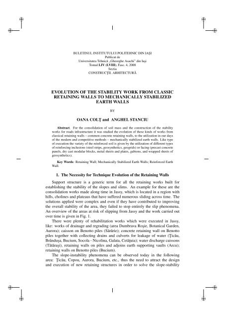
Abstract. For <strong>the</strong> consolidation <strong>of</strong> soil mass and <strong>the</strong> construction <strong>of</strong> <strong>the</strong> <strong>stability</strong><br />
<strong>work</strong>s for roads infrastructure it was studied <strong>the</strong> <strong>evolution</strong> <strong>of</strong> <strong>the</strong>se kinds <strong>of</strong> <strong>work</strong>s <strong>from</strong><br />
<strong>classic</strong>al <strong>retaining</strong> <strong>walls</strong> – common concrete <strong>retaining</strong> <strong>walls</strong>, <strong>to</strong> <strong>the</strong> utilization in our days<br />
<strong>of</strong> <strong>the</strong> modern and competitive methods – mechanically stabilized earth <strong>walls</strong>. Like type<br />
<strong>of</strong> execution <strong>the</strong> variety <strong>of</strong> <strong>the</strong> reinforced soil is given by <strong>the</strong> utilization <strong>of</strong> different types<br />
<strong>of</strong> reinforcing inclusions (steel strips, geosyn<strong>the</strong>tics, geogrids) or facing (precast concrete<br />
panels, dry cast modular blocks, metal sheets and plates, gabions, and wrapped sheets <strong>of</strong><br />
geosyn<strong>the</strong>tics).<br />
Key Words: Retaining Wall; Mechanically Stabilized Earth Walls; Reinforced Earth<br />
Wall.<br />
1. The Necessity for Technique Evolution <strong>of</strong> <strong>the</strong> Retaining Walls<br />
Support structure is a generic term for all <strong>the</strong> <strong>retaining</strong> <strong>work</strong>s built for<br />
establishing <strong>the</strong> <strong>stability</strong> <strong>of</strong> <strong>the</strong> slopes and slims. An example for <strong>the</strong>se are <strong>the</strong><br />
consolidation <strong>work</strong>s made along time in Jassy, which is located in a region with<br />
hills, cholines and plateaus that have suffered numerous sliding across time. The<br />
solutions applied were complex and even if <strong>the</strong>y have contributed <strong>to</strong> improving<br />
<strong>the</strong> overall <strong>stability</strong> <strong>of</strong> <strong>the</strong> area, <strong>the</strong>y failed <strong>to</strong> s<strong>to</strong>p entirely <strong>the</strong> slip phenomena.<br />
An overview <strong>of</strong> <strong>the</strong> areas at risk <strong>of</strong> slipping <strong>from</strong> Jassy and <strong>the</strong> <strong>work</strong> carried out<br />
over time is given in Fig. 1.<br />
There were plenty <strong>of</strong> rehabilitation <strong>work</strong>s which were executed in Jassy,<br />
like: <strong>work</strong>s <strong>of</strong> drainage and regrading (area Dumbrava Ros¸ie, Botanical Garden,<br />
Aurora); caisson on Benot<strong>to</strong> piles (Sărărie); concrete <strong>retaining</strong> wall on Benot<strong>to</strong><br />
piles <strong>to</strong>ge<strong>the</strong>r with collecting drains and culverts for leakage <strong>of</strong> water (T¸ icău,<br />
Brândus¸a, Bucium, Socola - Nicolina, Galata, Cetăt¸uia); water discharge caissons<br />
(Tătăras¸i), <strong>retaining</strong> <strong>walls</strong> on piles and adjoins earth supporting vaults (Arcu);<br />
<strong>retaining</strong> <strong>walls</strong> on Benot<strong>to</strong> piles (Bucium).<br />
The slope-in<strong>stability</strong> phenomena can be observed <strong>to</strong>day in <strong>the</strong> following<br />
area: T¸ icău, Copou, Aurora, Bucium, etc., thus <strong>the</strong> need <strong>to</strong> attract <strong>the</strong> design<br />
and execution <strong>of</strong> new <strong>retaining</strong> structures in order <strong>to</strong> solve <strong>the</strong> slope-<strong>stability</strong><br />
✐<br />
✐<br />
✐<br />
✐
✐<br />
✐<br />
✐<br />
✐<br />
28 Oana Colt¸ and Anghel Stanciu<br />
problems. This is why we present an <strong>evolution</strong> <strong>of</strong> <strong>stability</strong> <strong>work</strong>s methods<br />
including <strong>the</strong> utilization <strong>of</strong> <strong>the</strong> reinforced soil structures.<br />
Fig. 1. – Jassy slope-support structures in <strong>the</strong> sliding-affected areas.<br />
2. The Evolution <strong>of</strong> <strong>the</strong> Stability Structures<br />
To solve <strong>the</strong> problem <strong>of</strong> <strong>the</strong> construction <strong>of</strong> communication routes in areas<br />
with restrictions and for <strong>the</strong> stabilization <strong>of</strong> adjacent slopes at risk <strong>of</strong> slipping,<br />
over <strong>the</strong> time it has been seen an <strong>evolution</strong> <strong>of</strong> <strong>stability</strong> <strong>work</strong>s concepts <strong>from</strong> <strong>the</strong><br />
<strong>classic</strong>al <strong>retaining</strong> <strong>walls</strong> <strong>to</strong> reinforced or precast concrete <strong>retaining</strong> wall <strong>to</strong> various<br />
forms <strong>of</strong> reinforced soil.<br />
In summary, in time, <strong>the</strong> concept <strong>retaining</strong> wall sustains all <strong>the</strong> unstable soil,<br />
changed in<strong>to</strong> <strong>the</strong> concept where <strong>the</strong> soil sustained itself and <strong>the</strong> remaining forces<br />
are taken by <strong>the</strong> <strong>retaining</strong> wall.<br />
2.1. Classical Retaining Walls<br />
The first <strong>retaining</strong> structures realized was those made in concrete in various<br />
forms (Fig. 2) constructed <strong>of</strong> dry masonry, s<strong>to</strong>ne masonry or brick with mortar,<br />
concrete no-fines [1]. They ensure <strong>the</strong> takeover <strong>of</strong> <strong>the</strong> earth resistive forces<br />
(friction on <strong>the</strong> foot, etc.) generated by its own weight and a partial mobilization<br />
for a possible area <strong>of</strong> failure, shearing resistance <strong>of</strong> <strong>the</strong> earth. Most <strong>of</strong>ten, <strong>the</strong>se<br />
types <strong>of</strong> structures become non-economical due <strong>to</strong> <strong>the</strong>ir quite large size. Their<br />
use is recommended particularly where masonry material may be found in <strong>the</strong><br />
construction area.<br />
In order <strong>to</strong> reduce <strong>the</strong> size <strong>of</strong> <strong>the</strong>se <strong>retaining</strong> <strong>walls</strong> and especially in <strong>the</strong> case <strong>of</strong><br />
large heights, <strong>the</strong> idea <strong>of</strong> introducing discharge plates appeared, <strong>the</strong>y being named<br />
<strong>retaining</strong> <strong>walls</strong> with consoles or discharging plates (Fig. 3 a, b).<br />
The discharging plates and <strong>the</strong> consoles have a double role: <strong>to</strong> reduce <strong>the</strong><br />
values <strong>of</strong> active forces and <strong>to</strong> increase <strong>the</strong> <strong>stability</strong> <strong>of</strong> <strong>the</strong> earth wall, with <strong>the</strong><br />
✐<br />
✐<br />
✐<br />
✐
✐<br />
✐<br />
✐<br />
✐<br />
Bul. Inst. Polit. Ias¸i, t. LIV (LVIII), f. 4, 2008 29<br />
raising <strong>of</strong> <strong>the</strong> soil weight on <strong>to</strong> console <strong>to</strong> <strong>the</strong> weight <strong>of</strong> <strong>the</strong> wall. In addition, <strong>the</strong>re<br />
have been realized <strong>retaining</strong> <strong>walls</strong> with shafts and niches [2], (Fig. 3 c, d).<br />
Fig. 2. – The <strong>classic</strong>al <strong>retaining</strong> <strong>walls</strong> in various forms.<br />
Fig. 3. – Retaining <strong>walls</strong> with discharging consoles / discharging plates and niches.<br />
2.2. Concrete Steel Retaining Walls<br />
It appeared <strong>the</strong> possibility <strong>of</strong> reducing <strong>the</strong> size <strong>of</strong> <strong>the</strong> <strong>retaining</strong> <strong>walls</strong> using<br />
by <strong>the</strong>n, along with <strong>the</strong> emergence <strong>of</strong> <strong>the</strong> concrete steel in area <strong>of</strong> constructions;<br />
through <strong>the</strong> use <strong>of</strong> structural forms that have helped <strong>to</strong> increase <strong>the</strong> share <strong>of</strong> soil’s<br />
own weight in ensuring its <strong>stability</strong>, reduction <strong>of</strong> active earth pressure and <strong>the</strong><br />
mobilization <strong>of</strong> a part <strong>of</strong> <strong>the</strong> resistance <strong>to</strong> shearing on foot (Fig. 4). The crosssection<br />
<strong>of</strong> <strong>the</strong>se <strong>walls</strong> consists <strong>of</strong> a foundation plate that is embedded in <strong>the</strong> front<br />
wall [3], [4]. To increase <strong>the</strong> <strong>stability</strong> <strong>to</strong> <strong>the</strong> sliding wall, a heel key is appropriate<br />
<strong>to</strong> develop at <strong>the</strong> footing level.<br />
Reinforced concrete <strong>walls</strong> were developed <strong>from</strong> simple cross section <strong>to</strong><br />
complex ones. Thus, in order <strong>to</strong> reduce <strong>the</strong> active earth pressure and <strong>to</strong> increase<br />
<strong>the</strong> strength and <strong>stability</strong> <strong>of</strong> <strong>the</strong>se structures were introduced counterforts or<br />
buttresses and/or discharging plates (Fig. 4 d). In <strong>the</strong> case <strong>of</strong> high heights for<br />
<strong>retaining</strong> <strong>walls</strong> (over 5 m) <strong>the</strong> bending moments become very high and <strong>the</strong> use<br />
<strong>of</strong> <strong>the</strong> concrete steel <strong>retaining</strong> <strong>walls</strong> becomes unreasonable, and <strong>the</strong>refore has<br />
✐<br />
✐<br />
✐<br />
✐
✐<br />
✐<br />
✐<br />
✐<br />
30 Oana Colt¸ and Anghel Stanciu<br />
resorted <strong>to</strong> placing pretension reinforcements in <strong>the</strong> stretched areas <strong>of</strong> <strong>the</strong> <strong>retaining</strong><br />
wall (Fig. 4 e) [4].<br />
Fig. 4. – Active and passive reinforced concrete <strong>retaining</strong> <strong>walls</strong>.<br />
2.3. Anchored Retaining Walls<br />
The appearance <strong>of</strong> concrete steel and <strong>the</strong> pre-stretched elements favoured<br />
<strong>the</strong> emergence <strong>of</strong> new forms for <strong>the</strong> construction <strong>of</strong> <strong>the</strong> <strong>retaining</strong> <strong>walls</strong>, and <strong>the</strong><br />
development <strong>of</strong> anchored <strong>retaining</strong> <strong>walls</strong> (Fig. 5) [5].<br />
Fig. 5. – Anchored <strong>retaining</strong> <strong>walls</strong><br />
These structures are composed <strong>of</strong> a reinforced concrete element that is<br />
intended <strong>to</strong> convey <strong>the</strong> equivalent <strong>of</strong> <strong>the</strong> active or rest pressure <strong>to</strong> <strong>the</strong> land mass<br />
as possible tensions in <strong>the</strong> pre-stretched anchors. This sustain mainly comes <strong>from</strong><br />
<strong>the</strong> mobilization <strong>of</strong> <strong>the</strong> resistance through anchors.<br />
2.4. Mechanically Stabilized Earth Walls<br />
Starting <strong>from</strong> <strong>the</strong> idea <strong>of</strong> concrete steel and <strong>from</strong> <strong>the</strong> idea that <strong>the</strong> soil is selfsustainable<br />
in <strong>the</strong> slope <strong>to</strong> some extent, it appeared <strong>the</strong> concept <strong>of</strong> reinforced<br />
soil [6]. Thus, <strong>the</strong> basic idea <strong>of</strong> reinforced soil is using reinforcements in <strong>the</strong><br />
form <strong>of</strong> bands, bars, wires and sheets inserted between layers <strong>of</strong> soil and <strong>the</strong>y are<br />
likely <strong>to</strong> take up significant stretching efforts.<br />
However, as in reinforced concrete, <strong>the</strong>y are forming an assembly in which<br />
<strong>the</strong> reinforcements are located on land in <strong>the</strong> direction where <strong>the</strong> soil is solicited<br />
on stretching. In this solution, <strong>the</strong> <strong>retaining</strong> wall does not add additional efforts:<br />
<strong>the</strong> weight <strong>of</strong> <strong>the</strong> material <strong>from</strong> which <strong>the</strong> wall is made, <strong>the</strong> <strong>stability</strong> being given<br />
✐<br />
✐<br />
✐<br />
✐
✐<br />
✐<br />
✐<br />
✐<br />
Bul. Inst. Polit. Ias¸i, t. LIV (LVIII), f. 4, 2008 31<br />
by <strong>the</strong> weight <strong>of</strong> <strong>the</strong> reinforced soil mass and reinforced efforts stretching over <strong>the</strong><br />
reinforcements.<br />
The first modern system <strong>of</strong> soil reinforced was conceived and promoted since<br />
1966 by French engineer Henri Vidal, known as ”Terre Armée” (reinforced soil),<br />
(Fig. 7 a), [7], . . . , [10]. As reinforcement elements, Vidal used metallic bands<br />
and <strong>the</strong> facing was made <strong>from</strong> metallic elements.<br />
3. Mechanically Stabilized Earth Walls Evolution<br />
3.1. Terminology<br />
A <strong>retaining</strong> structure <strong>of</strong> reinforced soil consists <strong>of</strong> several items whose<br />
presentation is given in Fig. 6 [7], [11].<br />
Fig. 6. – Reinforced soil cross-section.<br />
Reinforced soil: it is <strong>the</strong> term used for all types <strong>of</strong> reinforced soil, created<br />
using multiple layers <strong>of</strong> inclusions, reinforcements.<br />
Reinforcements: generic term that defines all kinds <strong>of</strong> items made by humans,<br />
which incorporated in<strong>to</strong> <strong>the</strong> soil, improve its characteristics.<br />
Facing: it is part <strong>of</strong> reinforced soil systems, used <strong>to</strong> prevent collapse <strong>of</strong> soil<br />
layers <strong>of</strong> reinforcement.<br />
Filling soil: <strong>the</strong> soil, usually uncohesive where <strong>the</strong> reinforcements are placed<br />
for reinforcement.<br />
Retained backfill: <strong>the</strong> material located behind <strong>the</strong> reinforced soil.<br />
Foundation: ensure <strong>the</strong> verticality <strong>of</strong> <strong>the</strong> facing, used only for <strong>the</strong> facing <strong>of</strong><br />
reinforced concrete plates.<br />
3.2. Facing<br />
As we said, <strong>the</strong> facing is used <strong>to</strong> maintain <strong>the</strong> land between two layers <strong>of</strong><br />
reinforcement. The facing should be fairly resistant <strong>to</strong> retain local granules <strong>of</strong> soil<br />
that is between two reinforcements near <strong>the</strong> surface [11]. Also must be flexible<br />
as a whole <strong>to</strong> follow all <strong>the</strong> strains <strong>of</strong> massive reinforced soil without introducing<br />
additional efforts.<br />
✐<br />
✐<br />
✐<br />
✐
✐<br />
✐<br />
✐<br />
✐<br />
32 Oana Colt¸ and Anghel Stanciu<br />
The main types <strong>of</strong> facing used for reinforced soil are <strong>the</strong> following:<br />
Metallic facing is made <strong>of</strong> galvanized steel in <strong>the</strong> form <strong>of</strong> a cylinder cut in half.<br />
Such type <strong>of</strong> facing can be positioned on <strong>the</strong> horizontal direction, specifically for<br />
<strong>the</strong> first reinforced soil structures made in <strong>the</strong> 60’s, (Fig. 7 a), or vertically specific<br />
for <strong>the</strong> reinforced soil Ter-voile, (Fig. 7 b).<br />
Fig. 7. – Types <strong>of</strong> facing.<br />
Ter-voile [12] is relatively new used as a method <strong>of</strong> reinforced soil and <strong>the</strong><br />
basic idea in this method was <strong>the</strong> use <strong>of</strong> waste (metallic barrels) in construction<br />
materials, <strong>the</strong> facing made by cutting <strong>the</strong> barrels in two on vertical and reinforcements<br />
made in <strong>the</strong> form <strong>of</strong> braces.<br />
Due <strong>to</strong> <strong>the</strong> possibility <strong>of</strong> corrosion <strong>of</strong> metallic facing, it occurred <strong>the</strong> idea<br />
<strong>of</strong> using concrete for <strong>the</strong> facing in form <strong>of</strong> panels or precast concrete blocks<br />
(Fig. 7 c). They are relatively small and were designed and built especially for<br />
<strong>the</strong> construction <strong>of</strong> reinforced soil <strong>walls</strong>. The weight <strong>of</strong> <strong>the</strong>se blocks usually is<br />
between 10 and 15 kg. This type <strong>of</strong> facing is used for <strong>the</strong> soil reinforced with<br />
metallic strips and <strong>the</strong> connection between blocks and reinforcements are made<br />
by metallic connecting elements like safety catch pins and grooves.<br />
✐<br />
✐<br />
✐<br />
✐
✐<br />
✐<br />
✐<br />
✐<br />
Bul. Inst. Polit. Ias¸i, t. LIV (LVIII), f. 4, 2008 33<br />
Years later, in <strong>the</strong> early 70’s, <strong>the</strong>y have been proposed <strong>the</strong> use geosyn<strong>the</strong>tics<br />
for reinforced soil structures due <strong>to</strong> fear <strong>to</strong> a possible corrosion <strong>of</strong> metal<br />
reinforcements in <strong>the</strong> soil [13]. In France, <strong>the</strong> first geosyn<strong>the</strong>tics reinforcements<br />
<strong>work</strong>s were made in 1971. Were used <strong>the</strong> non-woven geotextiles for <strong>the</strong><br />
construction <strong>of</strong> a <strong>retaining</strong> wall <strong>of</strong> 4 m high located on a s<strong>of</strong>t and compressible<br />
soil and that’s why <strong>the</strong> need <strong>to</strong> make a supple structure. A section for this type<br />
<strong>of</strong> support structure is shown in Fig. 7 d. For this type <strong>of</strong> structure was used a<br />
geosyn<strong>the</strong>tic facing and <strong>the</strong> main advantage <strong>of</strong> this <strong>the</strong> method is that <strong>the</strong>re are no<br />
additional loads on <strong>the</strong> wall.<br />
Ano<strong>the</strong>r type is gabion facing, which can be used as a front <strong>to</strong> <strong>the</strong> reinforced<br />
soil with reinforcements <strong>of</strong> wire, metal bars, geogrids, geotextiles and <strong>the</strong> reinforcements<br />
are linked on <strong>the</strong> gabions in various ways. One <strong>of</strong> <strong>the</strong> reinforcement<br />
<strong>work</strong>s that uses this type <strong>of</strong> system facing is Terramesh [14] (Fig. 7 e). The<br />
particularity <strong>of</strong> this type <strong>of</strong> reinforcement system <strong>of</strong> <strong>the</strong> earth is <strong>the</strong> unit between<br />
<strong>the</strong> facing and <strong>the</strong> reinforcements, being used in this case <strong>the</strong> wire mesh, which at<br />
one end can be shaped executing <strong>the</strong> gabions.<br />
The facing <strong>of</strong> welded mesh is used for <strong>the</strong> reinforced soil named Tex<strong>to</strong>mur<br />
[15], (Fig. 7 f ). The facing elements <strong>of</strong> Tex<strong>to</strong>mur are 5 m long and are<br />
made <strong>of</strong> steel bars with a diameter <strong>of</strong> 8. . . 10 mm and <strong>the</strong> length reinforced is<br />
determined according <strong>to</strong> <strong>the</strong> design. The angle <strong>of</strong> inclination may be <strong>from</strong> 55 ◦ <strong>to</strong><br />
vertical. Ano<strong>the</strong>r way is <strong>the</strong> net bending edge welded <strong>to</strong> <strong>the</strong> wall <strong>to</strong> form <strong>the</strong> front.<br />
The structures were <strong>the</strong> metallic facing is used have <strong>the</strong> disadvantage <strong>of</strong><br />
corrosion. In <strong>the</strong> case <strong>of</strong> gabions or welded mesh facing for prevent <strong>the</strong> corrosion<br />
and erosion <strong>the</strong> metal can be galvanized. The advantage <strong>of</strong> such facing is low cost,<br />
rapid assembly, effective draining, which provides increased <strong>stability</strong>.<br />
The geosyn<strong>the</strong>tics facing are advantageous due <strong>to</strong> <strong>the</strong> elimination <strong>of</strong> corrosive<br />
fac<strong>to</strong>r and due <strong>to</strong> <strong>the</strong> potential reintroduction in<strong>to</strong> <strong>the</strong> natural structure by growing<br />
grass on <strong>the</strong> facing.<br />
3.3. Reinforcement<br />
Taking in<strong>to</strong> account that any material which has high resistance <strong>to</strong> stretching<br />
can improve <strong>the</strong> properties <strong>of</strong> <strong>the</strong> soil, we can state that <strong>the</strong> palette <strong>of</strong> materials<br />
used for reinforced soil is very large. Such reinforcements may be: flat steel,<br />
geosyn<strong>the</strong>tics, grid or metal, plastic, steel bolts. Depending on <strong>the</strong> material used<br />
and <strong>the</strong> direction <strong>of</strong> manifestation <strong>of</strong> stretching resistance <strong>of</strong> reinforcements, we<br />
can analyse several ways <strong>of</strong> reinforcing <strong>the</strong> soil.<br />
a) Reinforced soil with randomly distributed elements<br />
Practical applications <strong>of</strong> reinforced soil with randomly distributed elements<br />
are closely related <strong>to</strong> technology implementation. Since <strong>the</strong> end <strong>of</strong> <strong>the</strong> 60’s, <strong>the</strong>re<br />
were made considerable efforts <strong>to</strong> find a specific use for <strong>the</strong>m, but <strong>the</strong> results have<br />
remained unconvincing. However, <strong>the</strong> solution <strong>of</strong> this type <strong>of</strong> reinforcement has<br />
✐<br />
✐<br />
✐<br />
✐
✐<br />
✐<br />
✐<br />
✐<br />
34 Oana Colt¸ and Anghel Stanciu<br />
came later as Texsol which consists in reinforced soil with continue fibres [16].<br />
This way it came that <strong>the</strong> construction <strong>of</strong> reinforced soil wall <strong>from</strong> a mixture<br />
<strong>of</strong> powdery material reinforced with simple wire, made <strong>from</strong> textile or syn<strong>the</strong>tic<br />
material (disperse reinforcement – Fig. 8 a), by mixing <strong>the</strong>m and obtain a<br />
distribution <strong>of</strong> wires in all directions, which results in <strong>the</strong> emergence <strong>of</strong> apparent<br />
cohesion in any direction in all mass produced.<br />
Fig. 8. – Reinforced soil with randomly distributed elements – Texsol.<br />
The construction <strong>of</strong> <strong>the</strong>se kinds <strong>of</strong> reinforced soil structures requires a large<br />
<strong>work</strong> area because <strong>the</strong> technology takes place <strong>from</strong> <strong>the</strong> base <strong>of</strong> <strong>the</strong> wall <strong>to</strong> <strong>the</strong> <strong>to</strong>p,<br />
which coincides with <strong>the</strong> necessity <strong>of</strong> previous excavations and <strong>of</strong>ten use adding<br />
material.<br />
b) Linear reinforcements<br />
In addition <strong>to</strong> random placement <strong>of</strong> reinforcements in <strong>the</strong> ground, <strong>the</strong><br />
construction <strong>of</strong> reinforced soil <strong>the</strong> linear reinforcements can also be used <strong>to</strong>o<br />
(Fig. 9 a). Their basic feature is <strong>the</strong> form <strong>of</strong> a bar or strip and <strong>the</strong> linear<br />
effects <strong>of</strong> reinforcements (Fig. 7 a...c). This type <strong>of</strong> reinforcement is specific<br />
for reinforcements <strong>of</strong> metal materials. The practical advantage in using linear<br />
reinforcements is that <strong>the</strong> construction is very easy.<br />
Fig. 9. – Linear reinforcements.<br />
If <strong>the</strong> soil must be preserved in its natural state, <strong>the</strong> easiest solution is <strong>to</strong><br />
✐<br />
✐<br />
✐<br />
✐
✐<br />
✐<br />
✐<br />
✐<br />
Bul. Inst. Polit. Ias¸i, t. LIV (LVIII), f. 4, 2008 35<br />
introduce bars in holes drilled in soil. With minor changes <strong>to</strong> <strong>the</strong> technology<br />
<strong>of</strong> making anchorages, <strong>the</strong> inclusions bars may be introduced in <strong>the</strong> ground and<br />
<strong>the</strong>y interact on <strong>the</strong>ir entire length.<br />
This method is applied for <strong>the</strong> Clouage type <strong>of</strong> reinforced soil [17] (Fig. 9 b).<br />
Using this method, in <strong>the</strong> massif <strong>of</strong> soil that we want <strong>to</strong> maintain in place are<br />
placed steel bars, which are fixed by cementing or with syn<strong>the</strong>tic resin. On <strong>the</strong><br />
outside <strong>of</strong> <strong>the</strong> bolt body is fixed a plate <strong>of</strong> monolithic or prefabricated concrete,<br />
forming <strong>the</strong> facing <strong>of</strong> <strong>the</strong> reinforced soil and aims <strong>to</strong> take over <strong>the</strong> earth pressure<br />
and <strong>to</strong> transmit forward <strong>to</strong> <strong>the</strong> bolt, which <strong>work</strong>s <strong>to</strong> pluck. The main advantage<br />
consists in enhances <strong>the</strong> adherence soil–reinforcement’s thanks <strong>to</strong> <strong>the</strong> unchanged<br />
structure <strong>of</strong> sustain soil.<br />
An essential advantage <strong>of</strong> linear reinforcing is <strong>the</strong> reduction <strong>of</strong> <strong>the</strong> possibility<br />
<strong>of</strong> corrosion, due <strong>to</strong> <strong>the</strong> geometry <strong>of</strong> <strong>the</strong>se inclusions. The surface exposed <strong>to</strong><br />
corrosion being minimal compared <strong>to</strong> any o<strong>the</strong>r solution <strong>of</strong> reinforcements. On<br />
<strong>the</strong> o<strong>the</strong>r hand, this section is not very efficient because <strong>the</strong> contact between soil<br />
and reinforcements decreases significantly, <strong>the</strong>reby reducing <strong>the</strong> friction between<br />
<strong>the</strong> soil and <strong>the</strong> reinforcements.<br />
c) Continuous reinforcements<br />
Mechanical behaviour <strong>of</strong> <strong>the</strong> reinforcements located on levels fits very well <strong>the</strong><br />
geometry and construction <strong>of</strong> practical use in soil structures. However, using reinforcements<br />
<strong>from</strong> geosyn<strong>the</strong>tics materials (geogrids or geotextiles, Fig. 7 d, f ) [18],<br />
in <strong>the</strong> form <strong>of</strong> sheets placed in parallel planes, reinforcing being made on two<br />
directions (Figs. 7 a, 10 a). It can also be used metal reinforcements in <strong>the</strong><br />
form <strong>of</strong> welded wire mesh, which also have resistance <strong>to</strong> stretch in two directions<br />
(Figs. 7 e, 10 b).<br />
Among systems that use metal reinforcements, which have two directions<br />
<strong>of</strong> shearing, we have already reminded <strong>the</strong> Terramesh system, which has <strong>the</strong><br />
particularity <strong>of</strong> using wire-welded meshes as reinforcements and gabions as facing<br />
elements.<br />
Ano<strong>the</strong>r system that uses continuous reinforcing is Polyfelt [19], which is<br />
using geosyn<strong>the</strong>tics reinforcements (Fig. 10 c). The stages in construction <strong>of</strong> a<br />
reinforced soil wall with Polyfelt are similar <strong>to</strong> those <strong>of</strong> any wall <strong>of</strong> this type, <strong>the</strong><br />
difference appear in <strong>the</strong> use <strong>of</strong> recoverable casings that allow vertical positioning<br />
<strong>of</strong> <strong>the</strong> layers and ensuring <strong>the</strong> inclination <strong>of</strong> <strong>the</strong> facing that is made <strong>from</strong> <strong>the</strong><br />
reinforcements material.<br />
In this type <strong>of</strong> reinforced soil we will include <strong>the</strong> Tex<strong>to</strong>mur system (Fig. 7 f ),<br />
where <strong>the</strong> geotextiles reinforcements are placed in layers at a vertical distance <strong>of</strong><br />
500 mm; between <strong>the</strong>m is placed and compacted <strong>the</strong> cohesive or granular filling<br />
material. The advantages <strong>of</strong> this system is that local material can be used as filling<br />
material and <strong>the</strong>re can be made curves, corners or terraces in varying lengths and<br />
<strong>the</strong> construction is done without support.<br />
✐<br />
✐<br />
✐<br />
✐
✐<br />
✐<br />
✐<br />
✐<br />
36 Oana Colt¸ and Anghel Stanciu<br />
A special type <strong>of</strong> reinforced soil is Pneusol [20], (Fig. 10 d), that represents<br />
<strong>the</strong> result <strong>from</strong> <strong>the</strong> combination <strong>of</strong> two elements: tires and soil. The term ”tire”<br />
refers <strong>to</strong> all <strong>the</strong> waste tires (<strong>the</strong> sides and roll band), or whole tires. They are<br />
placed in layers and filled with compacted soil. The term ”soil” includes all types<br />
<strong>of</strong> cohesive or noncohesive soil, naturally or artificially made. We include Pneusol<br />
in <strong>the</strong> continuous reinforced soil because <strong>the</strong> connexion between <strong>the</strong> tires forms<br />
continuous reinforcements.<br />
Fig. 10. – Reinforced soil with continuous reinforcements.<br />
The main advantage <strong>of</strong> this system is economical because <strong>the</strong>re are used<br />
waste tires and <strong>the</strong> filling material does not require special characteristics. The<br />
circular shape <strong>of</strong> tires also allows easily making <strong>of</strong> curve <strong>walls</strong> with small radius<br />
<strong>of</strong> curvature.<br />
4. Advantages <strong>of</strong> Using <strong>the</strong> Reinforced Soil Walls<br />
The reinforced soil <strong>walls</strong> presents a number <strong>of</strong> advantages in comparison<br />
with traditional methods due <strong>to</strong> <strong>the</strong> materials used and <strong>the</strong> technologies applied.<br />
Among <strong>the</strong>m we may mention <strong>the</strong> use <strong>of</strong> simple and fast technologies <strong>of</strong><br />
construction, which does not require a broad set <strong>of</strong> machines and also do not<br />
require a special qualification <strong>of</strong> <strong>the</strong> construction <strong>work</strong>ers. For making <strong>the</strong><br />
reinforced soil structures we need a small <strong>work</strong>ing space, except for Texsol<br />
system, which needs a large <strong>work</strong>ing area. Because <strong>the</strong> structures <strong>of</strong> reinforced<br />
soil take over <strong>the</strong> strains is not necessary <strong>the</strong> use <strong>of</strong> rigid foundations. As <strong>the</strong> main<br />
construction material is soil, it can be easily used materials on <strong>the</strong> spot, which<br />
reduces costs considerably. Ano<strong>the</strong>r advantage is <strong>the</strong> possibility <strong>to</strong> reintroduce<br />
this kind <strong>of</strong> structure in<strong>to</strong> <strong>the</strong> nature by growing grass on <strong>the</strong> facing.<br />
✐<br />
✐<br />
✐<br />
✐
✐<br />
✐<br />
✐<br />
✐<br />
Bul. Inst. Polit. Ias¸i, t. LIV (LVIII), f. 4, 2008 37<br />
5. Conclusions<br />
The <strong>evolution</strong> <strong>of</strong> conceptual <strong>work</strong> <strong>to</strong> support <strong>the</strong> mass <strong>of</strong> soil was dictated<br />
<strong>to</strong> both <strong>the</strong> material and <strong>the</strong> permanent search for <strong>the</strong> mobilization <strong>of</strong> shearing<br />
resistance <strong>of</strong> <strong>the</strong> soil <strong>to</strong> ensure its <strong>stability</strong>. The most <strong>of</strong> <strong>the</strong> use <strong>of</strong> reinforced<br />
soil is in <strong>the</strong> field <strong>of</strong> <strong>retaining</strong> <strong>walls</strong>. The <strong>walls</strong> <strong>of</strong> reinforced soil behave like<br />
any types <strong>of</strong> <strong>retaining</strong> <strong>walls</strong> and <strong>the</strong>y can replace <strong>the</strong> <strong>classic</strong>al solutions used <strong>to</strong><br />
make <strong>the</strong> <strong>retaining</strong> <strong>walls</strong>, bridge abutment, etc. In some cases it might result a<br />
large economy, and sometimes <strong>the</strong> technology used for reinforced soil, taking in<br />
account <strong>the</strong> flexibility <strong>of</strong> structures, may be <strong>the</strong> only possible solution.<br />
Received, November, 12, 2008 ,,Gheorghe Asachi” Technical University, Jassy,<br />
Department <strong>of</strong> Transportation Infrastructure and<br />
Foundations<br />
e-mail: oanacolt@gmail.com<br />
REFERENCES<br />
1. Durdarov V., Sbornye fundamenty promyshlennyh zdanii. Moskva, 1966.<br />
2. Maior N., Păunescu M., Geotehnică s¸i Fundat¸ii. Edit. Did. s¸i Pedag., Bucures¸ti, 1973.<br />
3. Păunescu M., Pop V., Silion T., Geotehnică s¸i Fundat¸ii. Edit. Did. s¸i Pedag.,<br />
Bucures¸ti, 1982.<br />
4. Mihul A., Construct¸ii din be<strong>to</strong>n armat. Edit. Did. s¸i Pedag., Bucures¸ti, 1969.<br />
5. Hobst L., Zajic J., Ancorarea în roci. Edit. Tehnică, Bucures¸ti, 1981.<br />
6. Vidal H., La terre Armée. Ann. de l’Inst. Techn. du Bâtiment et des Travaux Publics,<br />
19, 223-224, 888–938 (1966).<br />
7. ∗ ∗ ∗, GP 093-06-Ghid privind proiectarea structurilor de pământ armat cu materiale<br />
geosintetice s¸i metalice. Univ. Tehn. de Constr., Bucures¸ti, 2006.<br />
8. Silion T., Răileanu P., Stanciu A., Fundat¸ii - Pământ armat. Inst. Polit. Ias¸i, 1980.<br />
9. Stanciu A., Contribut¸ii la dimensionarea lucrărilor din pământ armat. Ph.D. Diss.,<br />
Inst. Polit. Ias¸i, 1981.<br />
10. Stanciu A., Bot¸i N., Lungu I., Considerat¸ii privind noi tehnici de stabilizare a<br />
taluzelor s¸i a lucrărilor de sprijinire adiacente. al X-lea Congres Nat¸ional de Drumuri<br />
s¸i Poduri, 1998.<br />
11. Colt¸ O., Concept¸ii moderne în alcătuirea structurilor de sprijin din pământ armat.<br />
Techn. Report, ”Gheorghe Asachi” Techn. Univ., Jassy, 2006.<br />
12. Curt V., Morin J.P., Metulesco A., Un nouveau concept de soutènement: le procéde<br />
Ter-Voile. Ann. de l’Inst. Techn. du Bâtiment et des Travaux Publics, , 454 (1987).<br />
13. Holtz R., Geosyn<strong>the</strong>tics R&D – The ”Early” Days (1960 <strong>to</strong> circa 1985). Proc. <strong>of</strong> <strong>the</strong><br />
Koerner Res. Symp., Drexel University, Philadelphia, Pennsylvania, USA, 2004.<br />
14. ∗ ∗ ∗, www.maccaferri-northamerica.com. Terramesh System.<br />
15. ∗ ∗ ∗, www.keller-ge.co.uk. Tex<strong>to</strong>mur.<br />
16. Leflaive E., The Reinforcement <strong>of</strong> Granular Materials with Continuous Fibers. Proc.<br />
2nd Int. Conf. on Geotextiles, 721–726, Las Vegas, USA, 1982.<br />
✐<br />
✐<br />
✐<br />
✐
✐<br />
✐<br />
✐<br />
✐<br />
38 Oana Colt¸ and Anghel Stanciu<br />
17. ∗ ∗ ∗, www.terrasol.com. Clouterre, Clouage.<br />
18. Găzdaru A., Feodorov V., Manea S. et al., Geosinteticele în construct¸ii. Proprietăt¸i,<br />
utilizări, elemente de calcul. Edit. Acad., Bucures¸ti, 1999.<br />
19. ∗ ∗ ∗, www.polyfelt.com. Polyfelt.<br />
20. Long N.T., Le Pneusol. Techn. Report, Labora<strong>to</strong>ire Central des Ponts et Chaussées,<br />
Rapport des Labora<strong>to</strong>ires, série GT7, 1985.<br />
EVOLUT¸ IA LUCRĂRILOR DE SPRIJINIRE DE LA ZIDURILE DE<br />
SPRIJIN CLASICE LA STRUCTURILE DIN PĂMÂNT ARMAT<br />
(Rezumat)<br />
Pentru consolidarea masivelor de pământ s¸i realizarea structurilor de sprijin ca lucrări<br />
de artă în infrastructura căilor de comunicat¸ii s-a observat evolut¸ia aces<strong>to</strong>ra de la lucrările<br />
de sprijiniri clasice – ziduri de sprijin din be<strong>to</strong>n simplu, la utilizarea în zilele noastre a<br />
unor me<strong>to</strong>de moderne s¸i competitive – pământul armat. Ca moduri de execut¸ie varietatea<br />
me<strong>to</strong>delor de realizare a pământului armat este dată de utilizarea diferitelor tipuri de<br />
armături (metalice, geosintetice, geogrile) sau de parament (blocuri prefabricate din<br />
be<strong>to</strong>n, structuri metalice, geogrile în<strong>to</strong>arse sau geosintetice).<br />
✐<br />
✐<br />
✐<br />
✐