fiabilite des composants de puissance fiabilite des ... - Institut Farman
fiabilite des composants de puissance fiabilite des ... - Institut Farman
fiabilite des composants de puissance fiabilite des ... - Institut Farman
- No tags were found...

You also want an ePaper? Increase the reach of your titles
YUMPU automatically turns print PDFs into web optimized ePapers that Google loves.
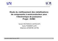
ThématiquesEPASF - FARMAN calculsFIABILITE DESCOMPOSANTS DEPUISSANCESylvain PIETRANICO (SATIE/LMT)Sylvie POMMIER (LMT)Stéphane LEFEBVRE (SATIE)
Fracture mechanism – (a)When extreme loads are applied, abrittle fracture of the ceramic isobservedThe crack path is normal to themaximum principal stress in theceramic layer .type (a) – failureBrittle fracture of the ceramicEssai <strong>de</strong> tractioncompression
Fracture mechanism – (b)Tiny crack near the copper/ceramicinterface – type (b) failure.Fatigue crack growth in copperalong the copper/ceramic interfaceEssai <strong>de</strong> tractioncompressionThe fatigue life of the componentis equal to the number of striationscounted on the fracture surface.This damage mechanisms is theone limiting the fatigue life.
ApproachCopperCeramic (NiAl or Si 3 N 4 )SingularitiesFE mo<strong>de</strong>lCopper – elastic plasticCeramic - elasticNon singular area : WEIBULL STRESS DISTRIBUTION-A crack initiation criteria-Stochastic : the fracture stress is statistically distributedbecause initiation sites statistically are statistically distributed (pores, grain boudary, second phases)-Scale effectsSingular area : FRACTURE MECHANICS FRAMEWORK-A crack growth criteria-Deterministic : no need to create a singularity, it pre-exists-Criteria : at which condition this singularity can move
Characterization of the materials : ceramics- brittle- failure stress statistically distributed- scale effect•Bending tests•2 ceramics- NiAl Aluminium nitri<strong>de</strong>-Si 3 N 4 Silicon nitri<strong>de</strong>•3 geometriesthin : t=0.5 mm , w=2.5large : t=0.5 mm , w=10 mmthick : t=1 mm , w=2.5 mmNiAl
Characterization of the materials : ceramicsPF( dV ) = 1 − P ( dV )S=Weibull distributionm⎛⎞⎜ dV ⎛ σ ⎞1 − exp − ⎟⎜⎜⎟V ⎟⎝o ⎝ σ 0 ⎠ ⎠Three points bendingtest
Characterization of the materials : ceramicsPF( dV ) = 1 − P ( dV )S=Weibull distributionm⎛⎞⎜ dV ⎛ σ ⎞1 − exp − ⎟⎜⎜⎟V ⎟⎝o ⎝ σ 0 ⎠ ⎠Three points bendingtestStress field in 3 points bendingσ22 yt⎛( x, y) = ⎜1− ⎟ σ max⎝xL⎞⎠
Characterization of the materials : ceramicsPF( dV ) = 1 − P ( dV )S=Weibull distributionm⎛⎞⎜ dV ⎛ σ ⎞1 − exp − ⎟⎜⎜⎟V ⎟⎝o ⎝ σ 0 ⎠ ⎠Three points bendingtestStress field in 3 points bendingσ22 yt⎛( x, y) = ⎜1− ⎟ σ max⎝xL⎞⎠PF( ) ( )V= 1 − P = − ∫S V 1 expV−dVVo⎛ σ⎜⎝ σ 0( x,y)⎞⎟⎠mWeakest link theorym⎛ ⎞⎜ ⎛ σW⎞= 1 − exp − ⎟⎜⎜⎟⎟⎝ ⎝ σ 0 ⎠ ⎠
Characterization of the materials : ceramicsPF( dV ) = 1 − P ( dV )S=Weibull distributionm⎛⎞⎜ dV ⎛ σ ⎞1 − exp − ⎟⎜⎜⎟V ⎟⎝o ⎝ σ 0 ⎠ ⎠Three points bendingtestStress field in 3 points bendingσ22 yt⎛( x, y) = ⎜1− ⎟ σ max⎝xL⎞⎠PF( ) ( )V= 1 − P = − ∫S V 1 expV−dVVo⎛ σ⎜⎝ σ 0( x,y)⎞⎟⎠mWeakest link theorym⎛ ⎞⎜ ⎛ σW⎞= 1 − exp − ⎟⎜⎜⎟⎟⎝ ⎝ σ 0 ⎠ ⎠Where, in 3 points bendingσW= σmax⎛⎜⎝V 1eff ⎞Vo⎟ ⎟ ⎠mandVeff⎛ σ x,= ∫ ⎜V ⎝ σ( )y⎞⎟⎠mdV=⎛V⎜2⎞⎟max ⎝ ⎠ 11( ) 2+m
Characterization of the materials : ceramicsP F= 1 −⎛exp⎜−⎜⎝⎛ σW⎜⎝ σ 0⎞⎟⎠m⎞⎟⎟⎠σW= σmax⎛⎜⎝V 1eff ⎞Vo⎟ ⎟ ⎠m⎛ L.t.w ⎞ 1V eff = ⎜ ⎟⎝ 2 ⎠ 1 + m( ) 2Aluminium Nitri<strong>de</strong>AlNmσ= 9.56o = 360MPaSilicon Nitri<strong>de</strong>Si 3 N 472m = 13.σ =o 470MPa
Characterization of the materials : ceramics- brittle- failure stress statistically distributed- scale effect•Bending tests•2 ceramics- NiAl Aluminium nitri<strong>de</strong>-Si 3 N 4 Silicon nitri<strong>de</strong>•3 geometriesthin : t=0.5 mm , w=2.5large : t=0.5 mm , w=10 mmthick : t=1 mm , w=2.5 mmNiAl
Range of applicabilityPF( )( )FEdV σ x,y,zV = 1 − exp ∫ − ⎜VFEVFEo⎛⎜⎝FEσ0⎟ ⎞⎠mWhereσFE( x,y,z )is the positive part of the maximum principal stress in the sub volume dVAluminium Nitri<strong>de</strong>AlNmσ= 9.56o = 360MPaSilicon Nitri<strong>de</strong>Si 3 N 4m = 13. 72σ =o 470MPaThe smallest AlN effective volume is equal to 0.07 mm 3The smallest Si 3 N 4 effective volume is equal to 0.03 mm 3 .( )1 dσxThe maximum value of is equal to 4mm -1 .σ ( x ) d x
ApproachCopperCeramic (NiAl or Si 3 N 4 )SingularitiesFE mo<strong>de</strong>lCopper – elastic plasticCeramic - elasticNon singular area : WEIBULL STRESS DISTRIBUTION-A crack initiation criteria-Stochastic : the fracture stress is statistically distributedbecause initiation sites statistically are statistically distributed (pores, grain boudary, second phases)-Scale effectsSingular area : FRACTURE MECHANICS FRAMEWORK-A crack growth criteria-Deterministic : no need to create a singularity, it pre-exists-Criteria : at which condition this singularity can move
Finite element simulationsCopperCeramic (NiAl or Si 3N 4)SingularitiesFor the Weibull analysis, thesingular area are exclu<strong>de</strong>d : ( )σ xd( x ) 11 σ−d x≥4mm
ApproachCopperCeramic (NiAl or Si 3 N 4 )SingularitiesFE mo<strong>de</strong>lCopper – elastic plasticCeramic - elasticNon singular area : WEIBULL STRESS DISTRIBUTION-A crack initiation criteria-Stochastic : the fracture stress is statistically distributedbecause initiation sites statistically are statistically distributed (pores, grain boudary, second phases)-Scale effectsSingular area : FRACTURE MECHANICS FRAMEWORK-A crack growth criteria-Deterministic : no need to create a singularity, it pre-exists-Criteria : at which condition this singularity can move
Singular area( ) ( )σ r , θ = rλ fθSharp corner (angle 90°), bi-materialTheoretical value (Bogy) : λ=-0.42
Singular area( ) ( )σ r , θ = rλ fθSharp corner (angle 90°), bi-materialTheoretical value (Bogy) : λ=-0.42Sharp corner (angle 90°), bi-material+ plasticity in copper+ finite thicknessesOr<strong>de</strong>r of the singularity from FE λ=-0.5« Generalized » stress intensity factorsare <strong>de</strong>termined
Singular area - approach•Assumption : Westergaard equations apply (checked by FE)•Extraction of the displacement field in the ceramic layer (elastic)•Extraction of K I and K II from this displacement field•Find the inclination α from the interface plane that maximisesK*I( α ) = C ( ) ( ) 11 α K I + C12α K II*K I( )αK*II( α ) = C ( ) ( ) 21 α K I + C 22 α K II•IfK * α max >I( ) K IC•the ceramic layer is broken along a plane inclined by an angle αmax
Summary-Singular area : the stress intensity factor amplitu<strong>de</strong> increasesduring the overload cycles but then is reduced duringsubsequent fatigue cycles-Non-singular area : the failure probability of the ceramicincreases during the overload cycles but then is reduced duringsubsequent fatigue cycles
Thèse Sylvain Pietranico : année 2• Etu<strong>de</strong> du comportement <strong><strong>de</strong>s</strong> métallisations souscontraintes thermiques <strong>de</strong> forte amplitu<strong>de</strong>• Essais <strong>de</strong> vieillissement accélérés, évolutions <strong>de</strong> paramètresélectriques liés au vieillissement.• Observation MEB du comportement <strong>de</strong> la couche <strong>de</strong> métallisationen cours <strong>de</strong> vieillissement• Modélisation, compréhension <strong><strong>de</strong>s</strong> mécanismes <strong>de</strong> vieillissement.
Essais <strong>de</strong> vieillissement accélérés :Régimes <strong>de</strong> court-circuitEssai <strong>de</strong> court circuit:Tcc=20µsE=300VIcc=80AEnergie dissipée =0,48J
Dedicated package from MicrosemiObjectives : to analyse the ageing of :- the metallization layer- the bond wires (contacts between wires and metallization)Dedicated modules have been realised by Microsemi(600V NPT IGBT and COOLMOS TM )
Caractérisations régulières effectuées :1. Variation <strong><strong>de</strong>s</strong> caractéristiques électriques du MOSChute <strong>de</strong> tension à l’état passant, tension <strong>de</strong> seuil, courants <strong>de</strong> fuite…2. Observation MEB du MOSVue <strong><strong>de</strong>s</strong>cellulesen coupeVue<strong>de</strong> la surfacesupérieure<strong>de</strong> la métallisation3. Corrélation entre la détérioration physique <strong>de</strong> la puce et la dégradation<strong><strong>de</strong>s</strong> caractéristiques électriques du MOS
Travaux en cours: Variation <strong><strong>de</strong>s</strong> caractéristiquesMesure <strong>de</strong> Rdson, transconductance, Idsat, Vth.Variations observées : Courant <strong>de</strong> saturationVgs (mV)
Travaux en cours: Mesure <strong>de</strong> résistivitéIVI (A)3.532.521.510.500 cycle29000cyclesNombres<strong>de</strong> cycles0.E+00 1.E-03 2.E-03 3.E-03 4.E-03 5.E-03 6.E-03 7.E-03V (V)R/R01.091.081.071.061.051.041.031.021.0110.990 2000 4000 6000 8000 10000 12000 14000E (J)Chute <strong>de</strong> la conductivité <strong>de</strong> la couche <strong>de</strong> métallisationLors <strong>de</strong> la répétition <strong><strong>de</strong>s</strong> cycles <strong>de</strong> court-circuit
Travaux en cours: Observation MebNeuf1000 cycles3000 cycles7000 cycles
Travaux en cours: Observation Meb11000 cycles15000 cycles21000 cycles29000 cycles
Travaux futurs : Métallisation• Corrélation entre la dégradation <strong>de</strong> la métallisation et les propriétés électriques <strong><strong>de</strong>s</strong> modules<strong>de</strong> <strong>puissance</strong>.• Caractérisations mécaniques <strong>de</strong> la couche d’aluminium• Réalisation d’éprouvettes par le LAAS• Observation MEB en fatigue, comparaison aux résultats obtenus lors <strong>de</strong> contraintes d’originethermomécaniquesGéométrie d’uneéprouvetteMasque <strong><strong>de</strong>s</strong> éprouvettes(2 wafer Si sont encours <strong>de</strong> réalisation)µmachine <strong>de</strong> traction
ThématiquescalculsAcknowledgementsFrench Research Agencies (DGA and CNRS)<strong>Farman</strong> institute of the Ecole NormaleSupérieure <strong>de</strong> Cachan.