1 ~\ J\ G J\ Z I I I r' - American Bonanza Society
1 ~\ J\ G J\ Z I I I r' - American Bonanza Society
1 ~\ J\ G J\ Z I I I r' - American Bonanza Society
- No tags were found...

Create successful ePaper yourself
Turn your PDF publications into a flip-book with our unique Google optimized e-Paper software.
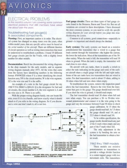
ELECTRICAL PROBLEMSIn this month's column I am covering some commonelectrical problems that ABS members have askedme about over the years.Troubleshooting fuel gauge(s)& associated components.Warning: First, an important caulion is in order. The electricalsystem has changed so many times over the years, oftenwithin model years, that allY specific advice 1I1lISr be based 011rhe serialllulIlber of rhe aircraft. There are different theoriesof circuit operation as well as wiring interconnection that mustbe understood to troubleshoot a problem. J found 19 differentfuel gauge circuits just for the V-tails, with a slightly lowernumber for other models.Documentation: Beech has documented the wiring diagramsin the shop manuals for the early models, and in separatewiring diagram manuals after 1975. All the wires that camefrom the factory have identifying numbers in the followingformat: FNNWZZS where F is a letter identifying the circuitfunction area, NN is the circuit number, W is the wire segment,ZZ is the wire size and S is the suffix.An example of a wire in the fuel gauge circuit for my1968 V35A D8663 is Q8A18. Q is the designator for fuel andoil circuits, the circuit number is 8, the wire segment is A andthe wire size is 18. There is no suffix.With the proper wiring diagram handy, one can locate thewire, even if it is in a bundle, and know exactly what it shou ldattach to if you refer to the wiring diagram. So if you disconnecta wire and don't mark it, all is not lost.Fuel gauge circuits: There are three types of fuel gauge circuitsfound in the <strong>Bonanza</strong>, Baron and Travel Air. But not allvariations are covered in these descriptions. I have discussedthe most common systems, so you need to verify rhe specificwirillg diagram for your aircraft before you jump imo lroubleshoolillgIhe syslem.Common to all systems, good connections-especially toground-is important and should always be checked.Early systems: The early systems are based on a resistivepotentiometer-like transmitter that is wired to a gauge thatreads current through the transmitter-the higher the current,the lower the indication. Most of the transmitters are of the 30-ohm variety. When the tank is full, the transtttitter will read 30ohms to ground. When the tank is empty, the transmitter willread close to zero ohms.On aircraft with aux tanks, there is usually a switch toselect the tank indicating on the gauge and some of the earliestaircraft share a single gauge with the left and right tanks.Some of the aux tanks have two transmitters that are wired inseries. For dual transmitters, each is about 15 ohms, adding to30 ohms when full and zero ohms when empty.To troubleshoot the system, remove the inspection panelabove the fuel transmitter. Remove the wire from the transmitterthat goes to the gauge. The gauge should read over full.If you short the wire to ground, it should read empty.The fuel transmitter should read 30 ohms when full andzero when empty. You can purchase a 30- to 50-ohm wirewoundpotentiometer and connect it to the wire going to thegauge and vary the resistance between 0 and 30 ohms to checkgauge calibration. At 15 ohms thegauge should read half. At 7.5 ohmsthe gauge should read 1/4, and at22.5 ohms it should read 3/4.To be within specification, thegauge needle should touch any partof the E mark when empty and anypan of the F mark when full.The only adjustment in thesystem is by bending the arm on~.-... the fuel transmitter to obtain a betterresult.1. au.. bar2. ruel quantity indicator drcult b"aker3, Fuel qua.ntlty Indicator4. TaM MLeetor awudl (mam • autLLa.ry)5. A\lX1lJ.aJ'7 tau Mleetor ."itch ()eft - rlptlI. RIFt w1nI break eonnector7. Tank traumltter untt (RR aumliuy)I. Tank uaumlttu unlt (LM aUlIIUi&rJ)I. Tank uu.mitter un1t (RH maitl)10. Tank truwnitter Wl1t (LH main)11. lAlt wtac break cc:mneetor12. Ma.ln taU .. lector (laft - rlPt)OPTlONAL AUXILlARY wnfG FUEL QUANTlTY INDICATOR CJRCUrrAirplane 8erW No. ~Sill thru D- ~J()1962 thru 1969 modelsThese models use resistivepotentiometers as transtttitters toprovide a voltage divider functionto a center-tapped gauge witb twomovement coils. The transmitters