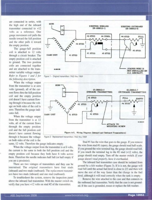
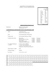
ELECTRICAL PROBLEMSIn this month's column I am covering some commonelectrical problems that ABS members have askedme about over the years.Troubleshooting fuel gauge(s)& associated components.Warning: First, an important caulion is in order. The electricalsystem has changed so many times over the years, oftenwithin model years, that allY specific advice 1I1lISr be based 011rhe serialllulIlber of rhe aircraft. There are different theoriesof circuit operation as well as wiring interconnection that mustbe understood to troubleshoot a problem. J found 19 differentfuel gauge circuits just for the V-tails, with a slightly lowernumber for other models.Documentation: Beech has documented the wiring diagramsin the shop manuals for the early models, and in separatewiring diagram manuals after 1975. All the wires that camefrom the factory have identifying numbers in the followingformat: FNNWZZS where F is a letter identifying the circuitfunction area, NN is the circuit number, W is the wire segment,ZZ is the wire size and S is the suffix.An example of a wire in the fuel gauge circuit for my1968 V35A D8663 is Q8A18. Q is the designator for fuel andoil circuits, the circuit number is 8, the wire segment is A andthe wire size is 18. There is no suffix.With the proper wiring diagram handy, one can locate thewire, even if it is in a bundle, and know exactly what it shou ldattach to if you refer to the wiring diagram. So if you disconnecta wire and don't mark it, all is not lost.Fuel gauge circuits: There are three types of fuel gauge circuitsfound in the <strong>Bonanza</strong>, Baron and Travel Air. But not allvariations are covered in these descriptions. I have discussedthe most common systems, so you need to verify rhe specificwirillg diagram for your aircraft before you jump imo lroubleshoolillgIhe syslem.Common to all systems, good connections-especially toground-is important and should always be checked.Early systems: The early systems are based on a resistivepotentiometer-like transmitter that is wired to a gauge thatreads current through the transmitter-the higher the current,the lower the indication. Most of the transmitters are of the 30-ohm variety. When the tank is full, the transtttitter will read 30ohms to ground. When the tank is empty, the transmitter willread close to zero ohms.On aircraft with aux tanks, there is usually a switch toselect the tank indicating on the gauge and some of the earliestaircraft share a single gauge with the left and right tanks.Some of the aux tanks have two transmitters that are wired inseries. For dual transmitters, each is about 15 ohms, adding to30 ohms when full and zero ohms when empty.To troubleshoot the system, remove the inspection panelabove the fuel transmitter. Remove the wire from the transmitterthat goes to the gauge. The gauge should read over full.If you short the wire to ground, it should read empty.The fuel transmitter should read 30 ohms when full andzero when empty. You can purchase a 30- to 50-ohm wirewoundpotentiometer and connect it to the wire going to thegauge and vary the resistance between 0 and 30 ohms to checkgauge calibration. At 15 ohms thegauge should read half. At 7.5 ohmsthe gauge should read 1/4, and at22.5 ohms it should read 3/4.To be within specification, thegauge needle should touch any partof the E mark when empty and anypan of the F mark when full.The only adjustment in thesystem is by bending the arm on~.-... the fuel transmitter to obtain a betterresult.1. au.. bar2. ruel quantity indicator drcult b"aker3, Fuel qua.ntlty Indicator4. TaM MLeetor awudl (mam • autLLa.ry)5. A\lX1lJ.aJ'7 tau Mleetor ."itch ()eft - rlptlI. RIFt w1nI break eonnector7. Tank traumltter untt (RR aumliuy)I. Tank uaumlttu unlt (LM aUlIIUi&rJ)I. Tank uu.mitter un1t (RH maitl)10. Tank truwnitter Wl1t (LH main)11. lAlt wtac break cc:mneetor12. Ma.ln taU .. lector (laft - rlPt)OPTlONAL AUXILlARY wnfG FUEL QUANTlTY INDICATOR CJRCUrrAirplane 8erW No. ~Sill thru D- ~J()1962 thru 1969 modelsThese models use resistivepotentiometers as transtttitters toprovide a voltage divider functionto a center-tapped gauge witb twomovement coils. The transmitters
are connected in series, withthe high end of the inboardtransmitter connected to + 12volts as a reference. Onegauge movement coil pulls theneedle toward the full positionand the other pu lls it towardthe empty position.The gauge-full positioncoil is attached to 12 vo ltsthrough a circuit breake r. Theempty position coil is attachedto ground. The two positioncoils are connected togetherand are attached to the transmittervariable voltage output.Refer to Figllres I and 2 fortire fol/olVing description.When the voltage outputfrom the transmitter is at zerovolts (ground ), all of the currentfl ows thru the full positioncoil and the empty positionco il doesn't have current Oowingthrough it because the voltageon both sides of the coil iszero. Therefore the gauge ind icates full.When the voltage outputfrom the transmitter is at 12volts, all of the current Oowsthrough the empty positioncoi l and the fu ll position coildoesn't have current flowingthrough it because the voltageDASH UNIT.....,.' 1 STUDf2 STUD IFigure 1 - Original transmitters 1962 thru 1969DASH UNITBUSS11 STUDIEXISTING INBOARD(95 -380012-1)11 STUD 13 STUD95-380012-5(INBOARD TRANSMITTER)*1 STUDEXISTING OUTBOARD(95-380012-3)'4 STUD*3 STUDJUMPER WlRE ISNOT INSTALLED ONALL AIRCRAFT.95-380012-7(OuTBOARD TRANSMITTER)FULLATTACH TOMOUNTING SCREWFIgure 4·3, Wlrlng Diagram (Inboard and Outboard Transmitter.)Figure 2 - Replocemenllronsmitters 1962 Ihru 1969on both sides of the coil is thesame, 12 volts. Therefore the gauge indicates empty.When the voltage output from the transmitter is at 6 volts,the current is the same in both the fu ll position coil and theempty position coi l because they both have 6 volts acrossthem. Therefore the needle indicates half full (or half empty ifyou are a pessimist).There are two vintages of transmitters and they can beintermixed. The original transmitters have four studs(i nboard) and two studs (outboard). The replacementtl'Onsmittel'Shave two studs (inboard) and one srud (outboard).To troubleshoot the system, remove the inspection panelabove the inboard fuel transminer. With the master switch on,verify that you have + 12 vo lts on srud #2 of the transminer.1EMPTYSrud #1 has the wire that goes to the gauge. If you removethe wire fro m stud #1 (open), the gauge should read half-scale.If you ground the wire terminal lug, the gauge should read full.If you touch the tenni nal lug to the #2 stud (+ 12 vo lts), thegauge should read empty. Turn off the master switch. If YOllrgallge doesn't read proper/y, have it overhallied.The inboard fuel transmitter case should be isolated fromground by a felt washer (Figure 3). If it is not, the gauge willread full until the acrual fuel level is close to 2/3 and then WIllmove the rest of the way faster than the change in the fuellevel , although it will read correctly when the tank is empty.Remove the wire attached to the case and that connects tothe outbound fuel transmitter. Verify that the case is not grounded.If the case is grounded, reseat or replace the felt washer.